Corradi Pergotenda Flux User manual

Pergotenda® Flux
Installation manual |EN
1 - 04.2014 Cod. 04838-IN


Dear Installer
This manual contains advice for a rapid and precise installation of the various components.
Although we are sure that you know how to use our products we still recommend that you read
our indications carefully.
We always welcome any suggestions or indications on possible improvements to the installation
techniques or the layout of the manual.
We would also remind you that during installation you should always use materials that are in full
respect of the environment.
It is also good practice to release, in addition to the declaration of conformity as required by law, a
final declaration of correct installation according to the specifications in the manual.
PER OTENDA®FLUX is a CORRADI S.p.A. product.
All technical interventions necessary for the installation must be carried out by authorised and
specialised technicians.
All unauthorised interventions (tampering, technical modification etc.) during the warranty period
will invalidate said warranty.
CORRADI S.p.A. reserves the right to make technical modifications to the components or pro-
ducts, except for the main features, at any time and without prior notice.
INSTALLATI N MANUAL
INDEX
Symbols 2
eneral precautions 2
eneral safety precautions 2
Precautions and warnings 2
Preliminary checks 3
Disposal of packaging materials 3
Controls and versions 4
Material check, unpacking and preparation 5
Features 6
Versions and motorisations 7
1 Mounting wall brackets 8
2 Mounting wall beam (optional) 12
3 Mounting guides/uprights 15
4 Mounting profile with Velcro 19
5 Mounting the transmission shafts 20
6 Assembly impact canvas awning 28
7 Mounting Impact canvas awning 38
8 Installation of assembled Impact awning 40
9 Pillar fixing 41
10 Tin hardware 42
11 Mounting lateral kit 46
12 Ermetika covering 48
13 ( ronda Mobile 2011) 49
Tables 50
Example - calculation of wind resistance based
on the loads and the anchors 53
1 - 04.2014 CORRADI SPA - INSTALLATION MANUAL - PER OTENDA®FLUX 1 di 53

1 - 04.2014
CORRADI SPA - INSTALLATION MANUAL - PER OTENDA®FLUX
2 di 53
SYMB LS
SYMB LS
The symbols indicated are used to draw the attention of the installer to arguments of particular
importance for the safety of persons, the product or to indicate particular operating conditions.
Attention: general operating note
Attention: greater attention to what you are reading
Attention: general hazard; possible risk for persons, property components
Attention: electrical hazard
Attention: risk of crushing hands
Contact: CORRADI S.p.A. or the authorised retailer
GENERAL PRECAUTI NS
Before undertaking any assembly, maintenance or cleaning operations, make sure that
you have fully understood the indications in this manual.
Failure to respect the regulations contained herein relieves CORRADI S.p.A. of all responsi-
bility for damage caused to persons, animals, property or components.
The installation personnel must scrupulously respect the local accident prevention regula-
tions in force.
All electrical connections for pergotenda®fluxment, installation of automation accessories
etc must only be made by qualified personnel.
If the structure is motorised and installed at a height of less than 250 cm from the ground, the
control button must be of the ‘dead-man’ type and the opening and closing operations must be
clearly visible.
In the case of any incompatibility, contact CORRADI S.p.A.
GENERAL SAFETY PRECAUTI NS
Destination of use
The PER OTENDA®FLUX is designed for a specific use (as outlined in this manual); any use other
than that envisaged shall relieve CORRADI S.p.A. of any responsibility.
When using the canvas it is good practice to remember that all moving parts can be a source of
danger.
Do not repergotenda®flux any coverings after the installation and, if they are repergo-
tenda®fluxd for maintenance, make sure that before removal the power supply is cut off
(in case of motorised pergotenda®fluxment).
It is recommended never to intervene on moving parts and to ensure that no operator is near to
the canvas before reactivating it after a technical or maintenance intervention.
It is compulsory to cut off the power supply (if present) when carrying out an installation,
repair or adjustment intervention.
It is recommended that a caution sign be placed on the electrical master switch with the
following indications:
"Attention! Do not touch. Service personnel at work"
PRECAUTI NS AND WARNINGS
The maintenance and installation personnel (assemblers, electricians…) must have sufficient
expertise and psychophysical and attitudinal requirements for undertaking the tasks at hand.
Always check the correct mounting and working efficiency of the electrical and manual drives
during the assembly.
In case of anomalies, immediately stop the work and contact the service department of
CORRADI S.p.A.


1 - 04.2014 CORRADI SPA - INSTALLATION MANUAL - PER OTENDA®FLUX 3 di 53
SYMB LS
The use of non-original spare parts, or unauthorised interventions or modifications shall
relieve CORRADI S.p.A. of any responsibility for damage caused to persons animals or pro-
perty.
It is absolutely forbidden to tamper with the fixings, the supports, the guides, the fixtures,
the command and idler units and any other component of the PER OTENDA®FLUX.
ATTENTI N
All values indicated are expressed in centimetres (unless otherwise specified).
PRELIMINARY CHECKS
On receipt of the packed goods and before starting their assembly, check the integrity of the
material and the presence of all the components necessary for the installation.
Carefully follow the information contained in the “Material check, unpacking and preparation”
section.
In case of anomalies immediately contact the authorised retailer or CORRADI S.p.A.
DISP SAL F PACKAGING MATERIALS
Divide the various packaging according to the material used (cardboard, nylon, polystyrene etc.)
and dispose of them separately in compliance with the regulations in force.

1 - 04.2014
CORRADI SPA - INSTALLATION MANUAL - PER OTENDA®FLUX
4 di 53
C NTR LS AND VERSI NS
WALL M UNTED C NTR LS (CUST MER RESP NSIBILITY)
To open the canvas, press the lower zone of the button, to
close the canvas, press the upper part. When the button is
released the canvas will stop its pergotenda®fluxment
immediately.
ELECTRIC C MMAND
In case of FLUX with a wall-switch, push the switch in the low
area in order to move the awning downwards, push it in the
up area to move the awning upwards. Once you release the
switch the awning will stop.
The drive must be installed between 90 and 120 cm off the
ground.
RADI C NTR L
If FLUX is equipped with radio control, the canvas lift, lower
and stop movements are explained in the “motor and
automatism” manual.
Awning going
downwards
Awning going upwards
FLUX
It is custom designed and built for the client to protect from
the sun and inclement weather, with the exception of snow;
The structure is fully self-supporting and may be used in winds
of up to class 8 on the Beaufort scale as shown in table 2.
On the anchored canvas version, the canvas must be removed
if the wind exceeds the values indicated in table 2.
MANUAL C NTR L
If the FLUX is fitted with manual drive, to open and close the
canvas, insert the winding handle in the seat of the gearbox
and turn clockwise (to raise the canvas) or anti-clockwise (to
lower the canvas).

1 - 04.2014 CORRADI SPA - INSTALLATION MANUAL - PER OTENDA®FLUX 5 di 53
CORRADI SPA
Via Brini, 39
40128 Bologna (ITALIA)
tel.051-4188411 - Fax.051-4188400
Cliente / Customer: XXXXXX
Indirizzo / Address: XXXXXXXXXXX
XXXXXXXXXXXXXXXXX
Ordine nr:
XXXX/X Collo/Pack
1 di 1
ETICHETTA
PESO
Packing list n°:
Contenuto/Content:
Mark:
Rif/Ref:
Numero:
XXXXXX
Comando
0010
FPSERVICE
xxxxxxxxxxxxx
L406396M0010
MATERIAL CHECK, UNPACKING AND PREPARATI N
PRELIMINARY CHECKS
The PER OTENDA®FLUX is delivered in a strong package that protects it from knocks or scratches.
There is a label on the package that indicates:
• Manufacturer data
• The order number
• Name of addressee
• Customer reference number
• Package number
Before opening the package, check that the data corresponds with that in your possession.
All the elements necessary for mounting the structure, the accessories needed for mounting and
the installation, the use and maintenance manual are inside the package.
N.B.:
Fixing elements such as screws, stoppers etc. are not included and must be chosen by the
installer based on the type of fixture foreseen (wall, wood, metal etc.)
Proceed as follows:
- Repergotenda®flux the elements from the packaging.
Attention:
do not use a knife to avoid the risk of ruining the paint or metal elements.
FACSIMILE PLATE

1 - 04.2014
CORRADI SPA - INSTALLATION MANUAL - PER OTENDA®FLUX
6 di 53
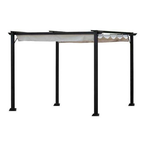
PER OTENDA® FLUX is a retractable covering
system custom made with curved runners to
protect against sun and rain (not suitable to
support snow), fixed to a supporting wall. It consists
of an aluminium structure and a stacking canvas.
Wind resistance is guaranteed up to class 6 on the
Beaufort scale.
The canvas, made from exclusive Corradi Eclissi*
fabric, available in white, grey and ivory, with
internal concealed obscuration layer and embossed
side with weft effect, is supported by intermediate
tubes (section: 4x5 cm) and terminals (section: 8x5
cm) set parallel to one another approximately every 45 cm.
It slides on runners with built-in splashguard (section 6x12 cm) on sliders with 6 misaligned
wheels with maximum capacity of 450 kg each.
The toothed drive belt inserted in each runner, with strands completely covered to
withstand salinity, is driven by a pulley and a single drive shaft to ensure even canvas
movement. The tensile strength at break of each belt is 894 kg.
The PER OTENDA® FLUX system is operated by a motor-reducer (electric drive) with the
possibility of radio control.
Aluminium tubular structure 6x12 cm, available in colours: brown, anthracite, white, grey,
ivory in glossy or matt finish; titanium and cor10 with matt finish. Runners available in
colours: brown, anthracite, white, grey, ivory in glossy or matt finish; titanium and cor10 with
matt finish. Support tubes available in colours: white, grey, ivory in glossy or matt finish.
Painted with certified Qualicoat cycle epoxy powders. AISI 304 stainless steel accessories and
10/10 aluminium protection covers matching the structure.
* See Corradi sample kit for other fabrics.
FEATURES
MAXIMUM DIMENSI NS cm
Width Projection
2 guides 500 650
3 guides 900 650
4 guides 1300 650

7 di 53
CORRADI SPA - INSTALLATION MANUAL - PER OTENDA®FLUX
1 - 04.2014
PERG TENDA®FLUX 2 GUIDES
PERG TENDA®FLUX 3 GUIDES
PERG TENDA®FLUX 4 GUIDES
PERG TENDA®FLUX
1
2
4
3
VERSI NS AND M T RISATI NS
WIDTH
PR JECTI N
HEIGHT F WALL SUPP RTS
HEIGHT F PILLARS A 220 volt - 218 W motor reducer complete with button limit switch for
ascent and descent. Ideal for flat awnings with 2, 3 or 4 guides because
the canvas is never stretched; or for tilted awnings up to 3 guides with a
maximum projection of 350 cm.
A 220 volt - 218 W motor reducer with control unit fitted with micropro-
cessor to control the voltage and a receiver for the radio-controlled
(433.92 MHz) remote control with a two channel transmitter. Ideal for
TILTED AWNIN S with 2 or 3 guides to guarantee with every manoeuvre
the correct canvas tension, which could change due to the dilatations of
the fabric or the guides caused by thermal excursions.
A 220 volt- 218+218 W motor reducer with control unit fitted with
microprocessor to control the voltage and for controlling the operation
of two motors in series on the same axis, a radio receiver for the radio-
controlled (433.92 MHz) remote control with a two channel transmitter.
Ideal for TILTED AWNIN S with 4 guides to guarantee with every
manoeuvre the correct canvas tension, which could change due to the
dilatations of the fabric or the guides caused by thermal excursions.
ELECTRICAL TYPE 2
SLOPE motor
remote computing system
exchange MONO
ELECTRICAL TYPE 3
1 SLOPE motor (control)
2 PLUS motor
remote computing system
exchange TANDEM
ELECTRICAL TYPE 1
PLAN motor
4

1 - 04.2014
CORRADI SPA - INSTALLATION MANUAL - PER OTENDA®FLUX
8 di 53
M UNTING WALL BRACKETS 1
fig. 1 - Trace on the wall
- the fixing line of the brackets at the height indicated in the project drawing (3);
- the external line of the brackets (1).
- the intermediate dimensions for fastening the central brackets (with 3-guide structure and
equal runner centres).
PAVIMENTO
==
fig. 2 - For 3-guide structures.
The intermediate bracket must be positioned with the central hole in correspondence with the
line marked on the wall.
==
1
3
3
1
FL R

1 - 04.2014 CORRADI SPA - INSTALLATION MANUAL - PER OTENDA®FLUX 9 di 53
fig. 3
Check the linearity of the tracing made with a spirit level.
1
3
fig. 4
Position the outside brackets on the line traced on the wall and mark the fixing holes.
1
3
1 M UNTING WALL BRACKETS

1 - 04.2014
CORRADI SPA - INSTALLATION MANUAL - PER OTENDA®FLUX
10 di 53
fig. 5
Drill the bracket fixing holes on the wall with a suitable drill bit.
fig. 6
- Insert the plugs (suitable for the type of wall and load, see table).
- tighten the screws;
- check the planarity of each bracket.
M UNTING WALL BRACKETS 1

11 di 53
CORRADI SPA - INSTALLATION MANUAL - PER OTENDA®FLUX
1 - 04.2014
2 M UNTING WALL BEAM ( PTI NAL)
fig. 7 – Trace on the wall
- the fixing line of the brackets at the height indicated in the project drawing (3).
- the external line of the brackets (1).
- the intermediate dimensions for fastening the central brackets (with 3-guide structure and
equal runner centres).
PAVIMENTO
==
fig. 8 - For 3-guide structures.
The intermediate bracket must be positioned in correspondence with the line marked on the wall.
==
1
3
FL R
3
1

12 di 53 CORRADI SPA - INSTALLATION MANUAL - PER OTENDA®FLUX 1 - 04.2014
M UNTING WALL BEAM ( PTI NAL) 2
fig. 9
Drill the bracket fixing holes on the wall with a suitable drill bit.
fig. 10
- Insert the plugs (suitable for the type of wall and load, see table).
- tighten the screws;
- check the planarity of each bracket.

13 di 53
CORRADI SPA - INSTALLATION MANUAL - PER OTENDA®FLUX
1 - 04.2014
fig. 11
- Insert the threaded plates (1) in the indicated seats on the beam (2).
- Screw in the bracket (3) using bolts and washers (4).
- Insert the top corner profile of the beam (2) into the folded end of the bracket (5) and tighten
using bolts and washers (5).
1
3
4
2
5
5
2 M UNTING WALL BEAM ( PTI NAL)

14 di 53 CORRADI SPA - INSTALLATION MANUAL - PER OTENDA®FLUX 1 - 04.2014
1
fig. 12
- Tighten the bolts.
- Insert the caps (1) in both ends of the beam.
M UNTING WALL BEAM ( PTI NAL) 2

15 di 53
CORRADI SPA - INSTALLATION MANUAL - PER OTENDA®FLUX
1 - 04.2014
fig. 13
- Insert the water drain flap (1), the bracket (2) and the foot (3) in this order at the bottom of the
upright.
- Screw in the plate (4) using the two screws (5).
- Fasten it to the upright using the four screws (6).
- Repeat the operation on all the uprights.
fig. 14
- Insert the splash profile (A) in the inner seats of the lateral guides up to about 14 cm. from the front end.
- Mount the bracket (1) on the studs (2) present on the guide (front part), then use the nuts provided (3) to
position the bracket at 1.5 cm. from the end of the profile.
- Insert the upright (4) into the bracket (1) on the guide and lock it using the two front screws (5).
- Pre-tighten the two rear screws (6) to the self-locking nuts (7) but do not over-tighten.
- Repeat the operation on all guides.
cm.1,5
cm.14
1
2
1
5
5
6
6
3
1
4
2
3
6
4
5
7
A
A
A
3 M UNTING THE GUIDES/UPRIGHTS

1 - 04.2014
CORRADI SPA - INSTALLATION MANUAL - PER OTENDA®FLUX
16 di 53
M UNTING THE GUIDES/UPRIGHTS 3
fig. 15 - Mounting the guides/uprights
Remove the screws (3) pre-mounted on the bracket (1), insert the guide into the rear bracket (2)
using the screws (3) without tightening them fully.
fig. 16 - Mounting motor support
The motor runner cross-bar with the four holes for anchoring the motor must be mounted in the
runner centre indicated on the project drawing (for 3 guides right - left).
For 4-guide structures, there are two motor runner cross-bars and they must be installed in the
outer clear openings.
Use the corner brackets (1) and the screws provided (2) to fit the runner cross-bars (3) to the beams.
2
1
2
3
3
1
1
3

17 di 53
CORRADI SPA - INSTALLATION MANUAL - PER OTENDA®FLUX
1 - 04.2014
1
3
2
3 M UNTING THE GUIDES/UPRIGHTS
fig. 17 - Assembling motor on runner cross-bar
The motor must be mounted on the runner cross-bar, where there are four screws, before the
cross-bar is positioned on the structure.
- partially unscrew two screws (1).
- completely unscrew the remaining screws (2).
- slide the motor plate until it is flush with the two screws on the runner cross-bar.
- tighten the remaining two screws to completely lock the motor.
Remove the screws on the runner cross-bar, fit the runner cross-bar with the motor facing the wall
to the beams with the screws previously loosened, positioning it so that the motor drive control
unit (3) is facing downwards.
fig. 18 - Mounting anti-torsion beam
Mount the anti-torsion beam (1), in correspondence with the motor, removing the screws pro-
vided (2) and fasten it to the angle bars (3) with the screws (2) previously loosened.
2
31

1 - 04.2014
CORRADI SPA - INSTALLATION MANUAL - PER OTENDA®FLUX
18 di 53
M UNTING THE GUIDES/UPRIGHTS 3
fig. 19 - Guide fixing
- Fully tighten all the guide/upright fastening screws.
fig. 20 - Guide fixing
- Fully tighten all the screws fastening the guide with the wall bracket.
Table of contents
Other Corradi Patio Furniture manuals
Popular Patio Furniture manuals by other brands

real living
real living VERRADO BS20010 Assembly instructions

ADEO Services
ADEO Services NAXOS 2021R09P07-0092 Assembly, Use, Maintenance Manual

Essential Garden
Essential Garden USD-047S owner's manual

Argos
Argos Granite Base 309/8363 Assembly instructions

Costway
Costway HW71518 manual

gaviota
gaviota CLIMATIKA Assembly instructions

kingsley-bate
kingsley-bate IP-90 Assembly instructions

PATIOJOY
PATIOJOY HW70891 manual

Treasure Garden
Treasure Garden Monaco BKM100 Assembly and operation guide

Patioflare
Patioflare 3 PC instructions

Royalcraft
Royalcraft Aspen Assembly instructions

Forever Redwood
Forever Redwood WOOD PATIO BENCH Assembly instructions