Corradi PERGOTENDA MAESTRO User manual

MAESTRO
PERGOTENDA®Installation manual


3 of 64CORRADI S.R.L. - INSTALLATION MANUAL - PERGOTENDA ® MAESTROREV.1 - 11.2019
CONTENTS
Dear installer,
In this manual you will nd all recommendations for a fast and precise installation of the components.
Sure of your expertise in the use of our products, we recommend you to strictly respect our indications.
We are also willing to accept suggestions and useful information on possible improvements both in
installation techniques and form of this manual.
We would like to remind you to always consider the installation conditions by checking with the most
attention the conformity of the chosen materials with the environmental conditions.
It is also a good rule to issue a nal declaration of correct installation according to the specications
provided for in this manual, beside the mandatory declarations of conformity required by law, where
requested.
MAESTRO is a product by CORRADI S.r.l.
Any technical operation necessary during the installation must be carried out exclusively by skilled and
authorised personnel.
Any personal operation (tampering with, technical changes, etc.) performed during the warranty period
voids the warranty immediately.
CORRADI S.r.l. reserves the right to apply technical changes to the components or the product,
except for the main features, at any time and without notice.
INSTALLATION MANUAL
TRANSLATION OF THE ORIGINAL INSTRUCTIONS CONTENTS
SYMBOLS.......................................................................................................................................................................................................................................... 4
CONTROLS AND VERSIONS ................................................................................................................................................................................................. 6
MATERIAL CHECK, UNPACKING AND PREPARATION.......................................................................................................................................... 7
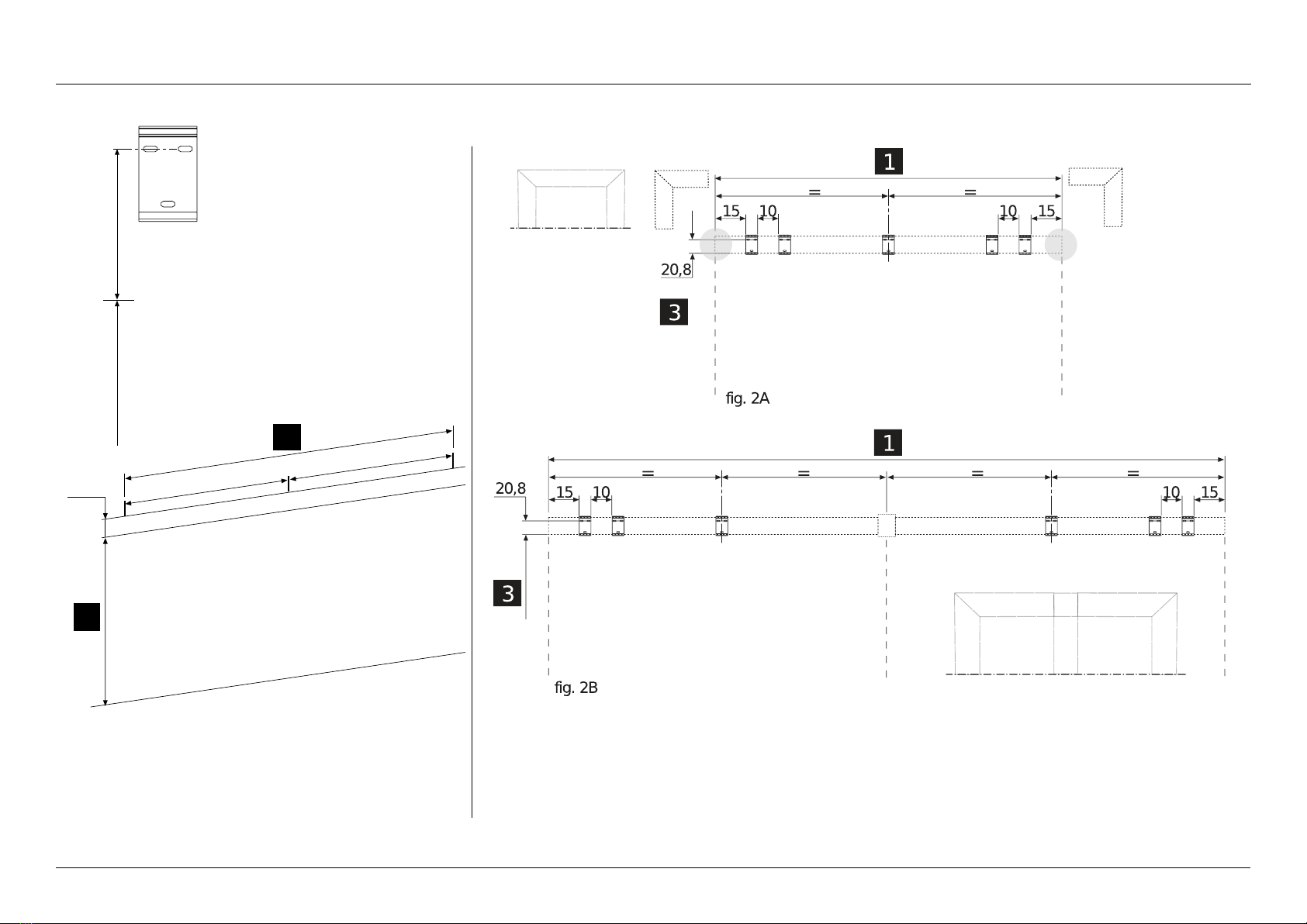
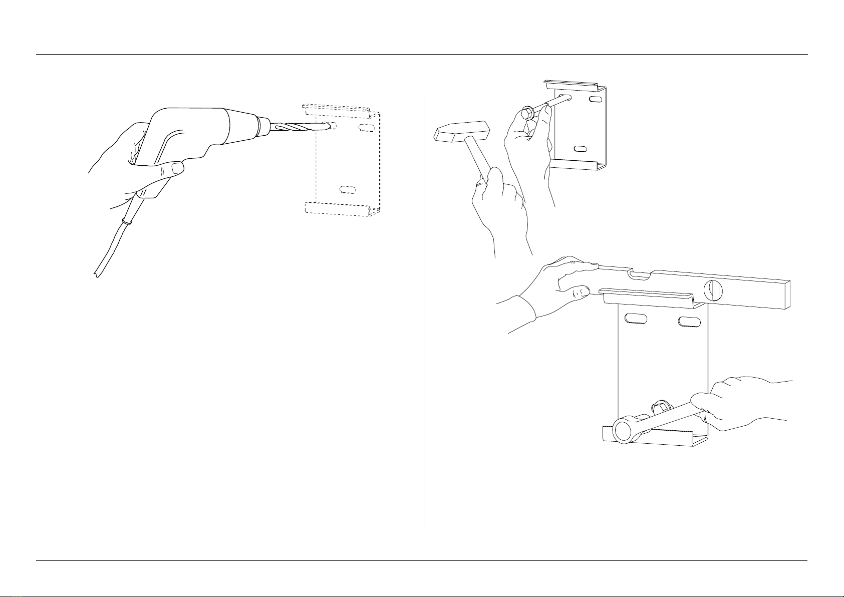
1 WALL INSTALLATION............................................................................................................................................................................................................ 8
2 PILLAR INSTALLATION......................................................................................................................................................................................................... 12
3 CROSSBEAM INSTALLATION ........................................................................................................................................................................................... 17
4 RUNNER INSTALLATION..................................................................................................................................................................................................... 26
5 CENTRAL RUNNER INSTALLATION OF A THREERUNNER STRUCTURE.............................................................................................. 27
6 TRANSMISSION SHAFT INSTALLATION.................................................................................................................................................................... 28
7 CONTROL UNIT INSTALLATION..................................................................................................................................................................................... 30
8 IMPACT AWNING CANVAS INSTALLATION ............................................................................................................................................................ 31
9 MOTOR CABLE INLET COVER CASING...................................................................................................................................................................... 32
10 MOBILE GUTTER................................................................................................................................................................................................................... 34
11 GUTTER PROFILE INSTALLATION .............................................................................................................................................................................. 38
12 SUPPORTING PROFILE INSTALLATION .................................................................................................................................................................. 40
13 SUPPLEMENTARY PILLAR............................................................................................................................................................................................... 41
14 SCREEN INSTALLATION.................................................................................................................................................................................................... 42
15 SLIDING GLASS DOORS INSTALLATION ............................................................................................................................................................... 45
16 DRIP GUARD PLATE INSTALLATION......................................................................................................................................................................... 46
17 CASING INSTALLATION.................................................................................................................................................................................................... 46
18 WALLMOUNTED OPTION WITH PILLARS........................................................................................................................................................... 50
19 WALLMOUNTED OPTION WITHOUT PILLARS................................................................................................................................................. 51
20 SILICONE APPLICATION AREAS.................................................................................................................................................................................. 52
21 ANGLE PLATE INSTALLATION ...................................................................................................................................................................................... 53
22 ANTIREBOUND SYSTEM INSTALLATION............................................................................................................................................................. 54
ELECTRIC SYSTEM...................................................................................................................................................................................................................... 61
TABLES ............................................................................................................................................................................................................................................... 62
EXAMPLE DETERMINATION OF THE WIND RESISTANCE ACCORDING TO THE LOADS AND THE DOWELS .............. 64

4 of 64 CORRADI S.R.L. - INSTALLATION MANUAL - PERGOTENDA ® MAESTRO REV.1 - 11.2019
CONTENTS
SYMBOLS
These symbols are used to draw the installer's attention to specic operating conditions or subjects of
particular importance for the safety of persons or the integrity of the product. GENERAL SAFETY WARNINGS
Intended use
Any misuse of MAESTRO relieves CORRADI S.r.l. from any responsibility.
Please remember that each moving part can represent a hazard.
GENERAL PRECAUTIONS
Before performing any installation, maintenance or cleaning operation, make sure to have
understood the content of this manual. Failure to respect the instructions provided herein
relieves CORRADI S.r.l. from any responsibility on damages to people, animals, property and/or
components. The installation personnel must thoroughly respect the local prevailing accident-
prevention regulations.
The electric connections for handling, installing automation accessories etc. must be performed
exclusively by skilled personnel.
If the structure is connected to a motor and installed at less than 250 cm from the ground, the
control button must be a “dead-man” switch button and the opening and closing movements
must be perfectly visible.
WARNINGS AND CAUTIONS
The installation personnel (installers, electricians, etc.) must have the specic skills and mental and
physical requirements necessary to perform the assigned tasks.
Upon installation, always perform preventive checks of the correct assembly, operation
and eciency of the manual and electric controls.
According to the prole length and weight, handle the same with the help of the suitable number of
operators specied by the regulations.
Attention: general operating note
Attention: pay utmost attention to the indications provided herein
Attention: general hazard - possibility of damage to people, property, components
Do not remove any casing after the installation; for structures provided with motors, we
recommend cutting o the power supply before performing any maintenance operation.
During the installation, maintenance, repair or adjustment operations, it is compulsory to cut
o the power supply.
We recommend putting a warning sign on the power supply main switch with the following
indication:
“Attention! Do not touch. Service personnel at work”.
In case of faults, stop the movements immediately and contact the technical service of
CORRADI S.r.l.
We recommend not to intervene on a moving part and make sure that no one is close to the structure
before reactivating it after a technical and maintenance operation.
Attention: electrical hazard
Attention: hand crushing hazard
Contact CORRADI S.r.l. or an authorised retailer
Should you nd any inconsistency, please contact CORRADI S.r.l.
SYMBOLS

5 of 64CORRADI S.R.L. - INSTALLATION MANUAL - PERGOTENDA ® MAESTROREV.1 - 11.2019
CONTENTS
SYMBOLS
The use of non-original spare parts, tampering with and unauthorised changes relieve CORRADI
S.r.l from any responsibility on damages to people, property or animals.
It is strictly forbidden to tamper with the connections, supports, runners, retainers, control and
transmission units, and any other component of MAESTRO.
ATTENTION
All indicated measures (unless otherwise specied) are expressed in centimetres.
PRELIMINARY CHECKS
When receiving the packed goods and before proceeding with the installation, check the material
integrity and the presence of all components necessary for the installation.
Thoroughly follow the information provided in the paragraph“Material check, unpacking and preparation”.
STORAGE AND MAINTENANCE
The packed components must be handled following consolidated procedures that prevent damages to
the product.
Before the installation, the goods can be stored, if necessary, in suitable areas to prevent damages and
deterioration.
In case of faults, contact CORRADI S.r.l. or an authorised retailer

6 of 64 CORRADI S.R.L. - INSTALLATION MANUAL - PERGOTENDA ® MAESTRO REV.1 - 11.2019
CONTENTS
WALL-MOUNTED CONTROL (BY THE CUSTOMER)
To orient the cover canvas, press the button on the upper or lower
side; when releasing it (neutral central position), the canvas will stop
in the desired position.
REMOTE CONTROL
MAESTRO has a motor with remote control. To open, close, and stop
the blades use the relevant buttons (see gure).
The use of the multi-channel remote control allows checking also
accessories (optional) like lights and side closures.
Replacement of the remote control battery 1
To replace the battery, remove the screw on the rear side of the
remote control and replace it with a similar model (12 Vdc alkaline
battery, mod. 23 AE).
Replacement of the remote control battery 2
This transmitter is supplied by a 3 Volt CR2032 battery. To replace the
battery, open the ap on the rear side, slide out the exhausted battery
and replace it with a new one respecting the polarity. Then t the ap
in the relevant seat.
Pay attention not to invert the polarity.
Pay attention not to use a wrong model.
Explosion hazard if the battery is replaced with a model other
than the specied one.
Dispose of the used battery in suitable containers.
CONTROLS AND VERSIONS
Canvas closure
DEAD-MAN BUTTON (NOT
SUPPLIED)
Canvas opening
LED
indicates the status
of the battery
(red means “working”)
Canvas closure
Canvas opening
Stop

7 of 64CORRADI S.R.L. - INSTALLATION MANUAL - PERGOTENDA ® MAESTROREV.1 - 11.2019
CONTENTS
MATERIAL CHECK, UNPACKING AND PREPARATION
PRELIMINARY INSPECTIONS
MAESTRO is delivered in sturdy packages that protect it from impacts or dents. The package has a label
indicating:
• the manufacturer data
• the order number
• the recipient name
• the customer reference name
• the package number
• The weight
Before opening the package, check that the data correspond to the ones you have.
The packages contain the elements and accessories required for the installation and the User manual.
Packages weighing between 25 kg and 55 kg must be handled by at least two people.
Proceed as follows:
- remove the components from the packages.
Note:
there are no retaining elements like screws and dowels since they must be decided by the
installer according to the type of mounting (wall-mounting, wood, metal, etc.).
Attention:
do not use a cutter to avoid damaging the metal element paint.
LABEL FACSIMILE
Corradi Srl
Via M. Serenari, 20 -
40013 Castelmaggiore (BO) Italy
T +39 051 4188 411 - F +39 051 4188 400
www.corradi.eu

8 of 64 CORRADI S.R.L. - INSTALLATION MANUAL - PERGOTENDA ® MAESTRO REV.1 - 11.2019
CONTENTS
1 WALL INSTALLATION
g. 1 - Trace on the wall
- the slot xing line at the height indicated in the project drawing
(3) + 20.8 cm;
- the external line of the total width (1);
- in case of side-by-side structures, trace the intermediate xing
measures of the central brackets.
FLOOR
HEIGHT UNDER BEAM
g. 2A
- Plate-to-wall xing drawing for single module.
g. 2B
- Plate-to-wall xing drawing for side-by-side module.
External side
External side
External side
External side
Central
pillar
HEIGHT UNDER BEAM

10 of 64 CORRADI S.R.L. - INSTALLATION MANUAL - PERGOTENDA ® MAESTRO REV.1 - 11.2019
CONTENTS
1 WALL INSTALLATION
Fig. 5
- Drill the xing holes of the brackets on the wall using a suitable bit.
Fig. 6
- Insert the dowels (suitable to the wall and the loads), (see table on page 51);
- tighten the screws;
- check the planarity of every single bracket.

11 of 64CORRADI S.R.L. - INSTALLATION MANUAL - PERGOTENDA ® MAESTROREV.1 - 11.2019
CONTENTS
1 WALL INSTALLATION
Fig. 7
- Bracket xing to wall for central and/or side pillar;
- if the project indicates a side-by-side module, use the bracket (B) as central component by xing
it to the wall following the operations described before.
NOTE: in case of side pillar, the wall-mounted bracket is not present.
Fig. 8
- Bracket xing to wall for central pillar;
- x the central pillar for wall installation (A) to plate (B) using 6 M8x16 screws (C).
A
C
HEIGHT UNDER BEAM
B

12 of 64 CORRADI S.R.L. - INSTALLATION MANUAL - PERGOTENDA ® MAESTRO REV.1 - 11.2019
CONTENTS
2 PILLAR INSTALLATION
Fig. 9
- Loosen the M8x16 BUTTON screw (C) and remove foot (A) from the pillar (B).
- The other 3 screws required for the next xing operation are in the accessories box.
Note: perform this operation on all pillars of the structure.
Fig. 10
- Orient the pillar feet (A) correctly and x them to the ground using suitable dowels. In doing this,
respect the parallelism and diagonals referring to the 4 holes at the corners of the ground plate.
ATTENTION TO THE INSTALLATION: The foot sides with the holes for the pillar
retaining screws are those of side (PROJECTION). In case of oor water drain, before
fastening to the ground, trim the punched sticker with a cutter in the area of the drain hole
and apply a bead of silicone in the hole as shown in (Det. X).
A
B
C
A
A
A
A
Det. X
PROJECTION
WIDTH
IMPORTANT: the 4 pillars must be positioned so as to obtain a “PERFECTLY” at structure; this is fundamental to ensure that rainwater correctly ows inside the pillars and does not spill over the
gutters.

13 of 64CORRADI S.R.L. - INSTALLATION MANUAL - PERGOTENDA ® MAESTROREV.1 - 11.2019
CONTENTS
2 PILLAR INSTALLATION
WIDTH SIDE
1
PROJECTION
SIDE 1
Det. X
SELF-SUPPORTING VERSION WITH SUPPLEMENTARY MODULE ON WIDTH SIDE
Important: the pillars must be positioned so as to obtain a “PERFECTLY” at structure; this is fundamental to ensure that rainwater correctly ows inside the pillars and does not spill over the
gutters.
Fig. 11
- Orient the pillar feet (A) correctly and x them to the ground using dowels suitable to the oor. In doing this, respect the parallelism and diagonals measures referring to the 4 holes at the corners of the ground plate.
ATTENTION TO THE INSTALLATION: The foot sides with the holes for the pillar retaining screws are those of side (PROJECTION). In case of oor water drain, before fastening to the ground, trim
the punched sticker with a cutter in the area of the drain hole and apply a bead of silicone in the hole as shown in (Det. X).
WIDTH SIDE
2
WIDTH SIDE
2
PROJECTION
SIDE 1
PROJECTION
SIDE 2 PROJECTION
SIDE 2
PROJECTION
SIDE 1
PROJECTION
SIDE 1
PROJECTION
SIDE 2
PROJECTION
SIDE 2
WIDTH SIDE
1
WIDTH SIDE
1
WIDTH SIDE
1
WIDTH SIDE
1
WIDTH SIDE
2
WIDTH SIDE
2

14 of 64 CORRADI S.R.L. - INSTALLATION MANUAL - PERGOTENDA ® MAESTRO REV.1 - 11.2019
CONTENTS
SELF-SUPPORTING VERSION WITH SUPPLEMENTARY MODULE ON PROJECTION SIDE
Important: the pillars must be positioned so as to obtain a “PERFECTLY” at structure; this is fundamental to ensure that rainwater correctly ows inside the pillars and does not spill over the
gutters.
Fig. 12
- Orient the pillar feet (A) correctly and x them to the ground using dowels suitable to the oor. In doing this, respect the parallelism and diagonals measures referring to the 4 holes at the corners of the ground plate.
ATTENTION TO THE INSTALLATION: for the side pillars, the foot sides with the screw xing holes of the pillar are those of the PROJECTION side (Y), whereas for the common central pillars
the foot sides with the holes for the pillar xing screws are those of the WIDTH side (Z). In case of oor water drain, before fastening to the ground, trim the punched sticker with a cutter in the
area of the drain hole and apply a bead of silicone in the hole as shown in (Det. X).
Det. X
WIDTH
SIDE 1
PROJECTION
SIDE 1
Y
Y
Z
Z
Y
Y
2 PILLAR INSTALLATION
PROJECTION
SIDE 2
PROJECTION
SIDE 1
PROJECTION
SIDE 2
PROJECTION
SIDE 1
PROJECTION
SIDE 2
WIDTH
SIDE 1
WIDTH
SIDE 2
WIDTH
SIDE 2
PROJECTION
SIDE 2
PROJECTION
SIDE 1
PROJECTION
SIDE 2
PROJECTION
SIDE 1
WIDTH
SIDE 1
WIDTH
SIDE 1
WIDTH
SIDE 2
WIDTH
SIDE 2

15 of 64CORRADI S.R.L. - INSTALLATION MANUAL - PERGOTENDA ® MAESTROREV.1 - 11.2019
CONTENTS
2 PILLAR INSTALLATION
Fig. 13
- Insert pillars (A) into feet (B).
Note: The pillars feature reinforcements on the upper side.
Note: The recesses (C) on the top edge of the pillar (that will act as drain holes for the gutters) must
be positioned inside the structure (det. X).
Apply a bead of silicone in the pillar/foot areas as shown in (det. Y).
Fig. 14
Fix the pillars to the feet using M8x16 BUTTON screws (A) (q.ty 4 each).
Note: Should it not be possible to reach the screws because the pillar is against a wall, after the
structure installation it is COMPULSORY to use the wall-mounting system on the upper beam.
A
B
A
B
A
B
A
A
Det. X
C
Det. Y
IMPORTANT: the 4 pillars must be positioned so as to obtain a “PERFECTLY” at structure; this is fundamental to ensure that rainwater correctly ows inside the pillars and does not spill over the
gutters.

16 of 64 CORRADI S.R.L. - INSTALLATION MANUAL - PERGOTENDA ® MAESTRO REV.1 - 11.2019
CONTENTS
2 PILLAR INSTALLATION
SELF-SUPPORTING VERSION WITH SUPPLEMENTARY MODULE ON WIDTH SIDE SELF-SUPPORTING VERSION WITH SUPPLEMENTARY MODULE ON PROJECTION SIDE
Det. X Det. X
Fig. 15
- Repeat the operations described in gures 13 and 14 following the installation drawings described in this image (det. X).

17 of 64CORRADI S.R.L. - INSTALLATION MANUAL - PERGOTENDA ® MAESTROREV.1 - 11.2019
CONTENTS
3 CROSSBEAM INSTALLATION
WALL-MOUNTED VERSION
A
B
C
D
E
Z
F
Fig. 16 - Wall-mounted beam assembly
- x the plate (A) with the relevant M8x16 screws (E)
- x the plate (B) with the relevant M8x16 screws (D)
- x the plate (C) with the relevant M8x16 screws (F)
- repeat the same operations on the opposite side.
Note: the beams are already tted with the brackets xed by Corradi S.r.l. for a possible side
closure (Z).
Fig. 17 - Wall-mounted beam assembly
Note: before installing the beams to the wall, install prole (A)
- Fix prole (A) with the suitable short self-drilling screws (B) at a distance of approximately 50 cm
one from the other (det. X).
ATTENTION: If side closures are foreseen to be installed on the lateral sides
it will be necessary to cut the prole as indicated in det. Y. Repeat the operation on
the opposite side if the side closure is foreseen.
Det. X
Cutting line
Configuration
without side
closure
Configuration
with side
closure
Det. Y
A B

18 of 64 CORRADI S.R.L. - INSTALLATION MANUAL - PERGOTENDA ® MAESTRO REV.1 - 11.2019
CONTENTS
Fig. 18
- Lay the beam (A) on the brackets (B) xed to the wall.
3 CROSSBEAM INSTALLATION
A
B
B
B
WALL-MOUNTED VERSION
Fig. 19 - Anti-lifting bracket assembly
Note: the anti-lifting plate is foreseen to be xed on the 4 side brackets (A).
A
A

19 of 64CORRADI S.R.L. - INSTALLATION MANUAL - PERGOTENDA ® MAESTROREV.1 - 11.2019
CONTENTS
3 CROSSBEAM INSTALLATION
WALL-MOUNTED VERSION
Fig. 20 - Anti-lifting bracket assembly
- Fix the plate (A) to the wall-mounted bracket (B) using the 2 supplied M8x16 screws (C).
Fig. 21 - Side beam assembly
Note: before the installation, check that the pillars are positioned correctly (see page 12).
- Insert the side beam (A) in the rear brackets (B) and the screws (C) in the relevant slots (D), see
det. X-Y.
A
A
C
B
B
C
A
WALL-MOUNTED VERSION
Det. Y
Det. X
A
C
D
B

20 of 64 CORRADI S.R.L. - INSTALLATION MANUAL - PERGOTENDA ® MAESTRO REV.1 - 11.2019
CONTENTS
Fig. 22 - Side beam assembly
- Tighten the M8x16 screws (A) to the side beam (det. X);
- tighten, without forcing, the screws (B) to the pillar (det. Y);
- repeat the operations on the opposite side.
WALL-MOUNTED VERSION
Det. Y
A
Det. X
A
A
B
3 CROSSBEAM INSTALLATION
Other manuals for PERGOTENDA MAESTRO
1
Table of contents
Other Corradi Patio Furniture manuals
Popular Patio Furniture manuals by other brands

Schaffner
Schaffner SANTIS 1466 Assembly instructions

PATIOJOY
PATIOJOY HW68667 manual

Tuuci
Tuuci OCEAN MASTER MAX series operating instructions

PATIOJOY
PATIOJOY HW71243 manual

Style selections
Style selections YJAU-001AB: 0401967 Quick start manual

Island Umbrella
Island Umbrella BISTRO Assembly instructions