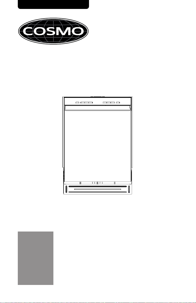
Cosmo COS-DWD24FBR User manual

DISHWASHER
COS-DWD24FBR
INSTALLATION MANUAL
IMPORTANT:
INSTALLER:
OWNER:
READ AND SAVE THESE INSTRUCTIONS.
FOR RESIDENTIAL USE ONLY.
PLEASE LEAVE THESE INSTRUCTIONS WITH THIS UNIT FOR
THE OWNER.
PLEASE RETAIN THESE INSTRUCTIONS FOR FUTURE
REFERENCE.
24 IN.BUILT-IN DISHWASHER
Rev.23.12

2
THANK YOU FOR YOUR PURCHASE
Thank you for your purchase. We know that you have many brands and
products to choose from and we are honored to know that you have decided
to take one of our products into your home and hope that you enjoy it.
COSMO Appliances are designed according to the strictest safety and
performance standard for the North American market. We follow the most
advanced manufacturing philosophy. Each appliance leaves the factory after
thorough quality inspection and testing. Our distributors and our service
partners are ready to answer any questions you may have regarding how to
install, use and care for your products. We hope that this manual will help you
learn to use the product in the safest and most effective manner.
Before using this product, please read through this manual carefully. Keep
this user manual in a safe place for future reference. Please ensure that other
persons using this product are familiar with these instructions as well.
If you have any questions or concerns, please contact the dealer from whom you
purchased the product, or contact our Customer Support at:
1-888-784-3108
Reach us online at:
www.cosmoappliances.com

3
TABLE OF CONTENTS
DISHWASHER SAFETY ......................................................................... 4
INSTALLATION REQUIREMENTS .......................................................... 6
Tools and Parts ........................................................................................6
Location Requirements ..........................................................................8
Drain Requirements ..............................................................................10
Water Supply Requirements ...............................................................11
Electrical Requirements ..........................................................................11
INSTALLATION INSTRUCTIONS ..........................................................12
Unpack Dishwasher ...............................................................................12
Remove Kick Plate ................................................................................ 13
Check Door Balance ............................................................................ 14
Adjust Leveling Legs ............................................................................. 14
Prepare Installation Opening ............................................................ 16
Verify Existing Utility Connections .......................................................17
When There Are No Existing Utility Connections ............................ 18
Connect Drain Hose to Dishwasher ................................................... 21
Slide Dishwasher Partially Into Opening .......................................... 21
Level Dishwasher .................................................................................. 22
Connect to Power Supply ................................................................... 23
Connect to Water Supply ................................................................... 26
Connect to House Drain System ........................................................ 27
Secure Dishwasher ................................................................................ 31
Pre-Test Checklist ................................................................................ 33
Test Dishwasher ................................................................................... 34
Replace the Kick Plate ......................................................................... 35
WARRANTY ........................................................................................36

4
DISHWASHER SAFETY
READ ALL INSTRUCTIONS BEFORE USING THE APPLIANCE
Your safety and the safety of others are very important.
We have provided many important safety messages in this manual and on
your appliance. Always read and obey all safety messages.
This is the safety alert symbol.
This symbol alerts you to potential hazards
that can kill or hurt you and others.
All safety messages will follow the safety alert
symbol and either the word "WARNING" or
"CAUTION." These words mean:
You can be killed or seriously injured if you
don't follow instructions.
A potentially hazardous situation which, if not
avoided, could result in minor or moderate
injury.
All safety messages will tell you what the potential hazard is, tell you how
to reduce the chance of injury, and tell you what can happen if the
instructions are not followed.
WARNING
CAUTION
California Proposition 65 Warning
WARNING:
Cancer and Reproductive Harm - www.P65Warnings.ca.gov.
A potentially dangerous voltage constituting
a risk of electrical shock is present that could
result in death or serious injury.
CAUTION

5
WARNING/GROUNDING INSTRUCTIONS
Improper connection of the equipment-grounding conductor can
result In a risk of electric shock. Check with a qualified electrician or
service representative if you are in doubt whether the appliance is
properly grounded. Do not modify the plug if provided with the
appliance. If the plug will not fit the outlet, have a proper outlet
installed by a qualified electrician.
For a grounded, cord-connected appliance:
This appliance must be grounded. In the event of a malfunction or
breakdown, grounding will reduce the risk of electric shock by
providing a path of least resistance for electric current. If this appliance
is equipped with a cord having an equipment-grounding conductor
and a grounding plug, the plug must be plugged into an appropriate
outlet that is installed and grounded in accordance with all local codes
and ordinances.
For a permanently connected appliance:
This appliance must be connected to a grounded metal, permanent
wiring system, or an equipment-grounding conductor must be run with
the circuit conductors and connected to the equipment-grounding
terminal or lead on the appliance.
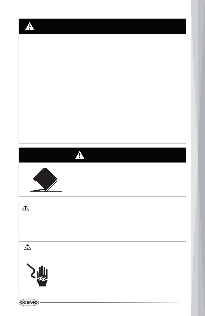
WARNING
TIP OVER HAZARD
• Do not use dishwasher until completely installed.
• Do not push down on open door.
• Doing so can result in serious injury or cuts.
SUFFOCATION HAZARD
• Before you throw awayyour old appliance,remove the door or lid so
that children cannot hide or get trapped inside your old appliance.
• Failure to follow these instructions can result in deathor brain damage.
Electrical Shock Hazard
To reduce the risk of electric shock, fire or injury to persons:
WARNING:
• The installer must ensure that the dishwasher is
completely enclosed at the time of installation.
• Care shall be exercised when the dishwasher is
installed or removed to reduce the likelihood of
damage to the power cord.

6
INSTALLATION REQUIREMENTS
TOOLSANDPARTS
Gather the required tools and parts before starting installation.
PARTSSUPPLIED
Adjustment cap (4)
Flat-head
Wood Screws
Screw-type Hose
Clamp (1)
PARTS NEEDED (NOT PROVIDED)
UL Listed Wire Nuts (3)
Strain Relief
3/8" braided
dishwasher supply hose
or Copper Tubing
Water Line (3/8" min.)
3/4" FHT x 3/8" OD
compression 90 elbow
(if not included in hose kit)
ST4x30mm (4)
Power Supply Cord

7
TOOLSNEEDED
Phillips-head
Screwdriver 5/16" and 1/4"
Nutdriver Level
Flashlight 6" Adjustable Wrench Measuring Tape
Carpenters Square Safety Glasses Bucket
Gloves Flat-bladed
Screwdriver
NEW INSTALLATIONS(ONLY)
PARTSNEEDED
Hand Shut-off Valve Waste Tee
(house plumbing, if
applicable)
Air Gap for drain hose
(if required)
Coupler (extending
drain line, if applicable)

8
TOOLSNEEDED
Tubing Cutter Hole Saw Set Drill and Bits
Wire Stripper
KEY CONNECTION POINTS
Front
ab
a
Water Connection
b
Electrical Junction Box
LOCATION REQUIREMENTS
IMPORTANT:
• Do not run drain lines, water lines or electrical wiring where they can interfere
with or contact dishwasher motors or legs.
• The location where the dishwasher will be installed must provide clearance
between motors and flooring. Motors should not touch the floor.
• The opening must have a level floor. (If floor at front of opening is not level
with floor at rear of opening, shims may be needed to level dishwasher).
• Do not install dishwasher over carpeted flooring.
• The dishwasher must be fully enclosed on the top, sides and back and must
not support any part of the enclosure.
• The dishwasher must be installed so that the drain hose is no more than 10 ft in
length for proper drainage.

9
OPENING DIMENSIONS
a
b
c
a
Countertop
b
Dishwasher
c
Clearance for Door
Opening 2" Minimum
3"
(7.6 cm)
5.5"
(14.0 cm)
* Make sure water line, wires and drain hose are within the shaded area.
23.8" (605 cm)
Min
22.8"
(57.9 cm)
Min
34" to 35"
(86.4 cm to 88.9 cm)
27"
(68.5 cm)
• The rough cabinet opening must be at least 23.8" (60.5 cm) wide, 22.8" (58
cm) deep and 34" (86.4 cm) high, and provide easy access to water,
electricity and a drain.
• When installed in a corner location, a 2" (5.1 cm) minimum clearance is
required between the side of the dishwasher and the adjacent wall, cabinet
or other appliance.
• There must be a minimum clearance of 27" (68.5 cm) in front of the
dishwasher to allow the door to fully open.

10
PRODUCT DIMENSIONS
22.68"
(57.6 cm) 23.57"
(59.86 cm)
33.66"
(85.5 cm)
18.66"
(47.4 cm)
3.8"
(9.7 cm)
DRAIN REQUIREMENTS
Follow local codes and ordinances.
DRAIN HOSE
If the supplied hose is not long enough, use a new drain hose with a maximum
length of 6 ft (3.05 m) that meets all current AHAM/IAPMO test standards.
The drain hose should:
• Be resistant to heat and detergent
•Have an inside diameter (I.D.) of 5/8" (1.58 cm) or 3/4" (1.9 cm) or 1" (2.54 cm)
• Include a coupler to connect the two hose ends (secure the connection with
two clamps)
Do NOT connect drain hoses from other appliances to the dishwasher drain hose.
Drain Hose Routing
The drain hose may pass through the same hole as the wiring and hot water line,
or you can cut an additional 1 ¹⁄₂" (3.8 cm) diameter hole in the cabinet wall to
admit the drain hose.
NOTE: The hole must be smooth with no sharp edges.

11
DRAIN CONNECTION HEIGHT
The drain connection method depends on the height of the drain
hose connection.
IMPORTANT: Failure to connect the drain hose at a height of 18" with
air gap (not provided) OR to create a drain loop with a minimum
height of 32" (81.3 cm) will result in improper draining of the
dishwasher.
WATER SUPPLY REQUIREMENTS
• Water pressure from the hot water supply line must be between
20-120 psi (138-862 kPa).
• Water heater that is adjusted to a water temperature of 120°F to
150°F (49°C to 65.5°C).
• A 3/8" min. diameter copper tubing water line extending at least
24" (61 cm) from the rear wall, and routed to connect to the front
left-hand side of the dishwasher.
• A hand shut-off valve in an accessible location, such as under the
sink (optional, but strongly recommended).
ELECTRICAL REQUIREMENTS
Electrical Shock Hazard
• Installation and service must be performed by a qualified
installer or service agency.
• Always disconnect the power before servicing this unit.
• This appliance must be properly grounded.
• Failure to do so could result in death, fire, or electrical shock.
WARNING:
IMPORTANT:
• The dishwasher must be supplied with 120 volt, 60 Hz., and connected to a
dedicated, properly grounded branch circuit, protected by a 15 or 20
ampere circuit breaker or time delay fuse.
• Maximum of two field wiring supply conductors (12 AWG Maximum) plus
one grounding conductor are permitted in the terminal box.
• Use Only copper wire.
• Wiring must be 2-wire with ground.
• Use a UL Listed/CSA Approved metallic strain relief.
• Be sure that the electrical connection and wire size are adequate and in
conformance with the National Electrical Code, ANSI/NFPA No. 70-latest
edition and all local codes and ordinances.
• If the electrical supply does not meet the above requirements, call a
licensed, qualified electrician before proceeding.

12
Grounding Instructions:
• The dishwasher must be connected to a grounded metal, permanent wiring
system, or an equipment grounding conductor must be run with the circuit
conductors and be connected to the equipment grounding terminal or lead
on the dishwasher.
Power Cord Connections:
Direct Wire Connections:
• Use flexible, armored or nonmetallic sheathed, copper wire with grounding
wire that meets the wiring requirements for your local codes and ordinances.
INSTALLATION INSTRUCTIONS
IMPORTANT:
• This appliance should be installed only by a qualified Installer, plumber or
technician and in accordance with the manufacturer’s installation
instructions, electrical and plumbing national and local codes and
ordinances.
• The dishwasher must be installed to allow for future removal from the
enclosure if service is required.
• Each dishwasher is tested at the factory and may contain some residual
water in the tub as a result of the test.
Step 1: UNPACK DISHWASHER
IMPORTANT: If you received a damaged dishwasher, you should immediately
contact Cosmo Customer Service.
SUFFOCATION HAZARD
• To avoid danger of suffocation, keep plastic bag and other
packing material away from babies and children. Do not use
this bag in cribs, carriages and playpens. The plastic bag
could block nose and mouth and prevent breathing. This
bag is not a toy.
• Failure to follow these instructions can result in death or
brain damage.
• Use a UL Listed power cord kit marked for use with dishwasher. Power cord
connections must comply with the National Electrical Code, Section 422
and/or local codes and ordinances.
• Recommended cord length is 54" min. and 64" max.

13
SUFFOCATION HAZARD
• Before you throw away your old appliance, remove the door or lid so that
children cannot hide or get trapped inside your old appliance.
• Failure to follow these instructions can result in death or brain damage.
1. With the help of two or more people, open the dishwasher door slowly
while one person presses down on the top of the dishwasher. Remove the
lower dish rack and all packing material.
2. Locate the literature package, and read the User Manual for operating
instructions.
3. Close the dishwasher door until latched, and stand the dishwasher upright.
4. Properly dispose of/recycle all packing material.
Step 2: REMOVE KICK PLATE(S)
a
a
Kick Plate Screws (2)
1. Using a screwdriver, remove the two screws attaching the kick plate(s) to
the cabinet.
2. Lift off the kick plate(s).

14
STEP 3: CHECK DOOR BALANCE
With another person holding the dishwasher to prevent it from tipping,
open the door slowly.
• If the door drops too freely, increase the spring tension.
• If the door closes too hard, decrease the spring tension.
To adjust the spring tension:
1. Grasping the spring firmly, raise or lower the hook end to the next
higher or lower slot, and then insert the hook into the slot.
NOTE: Adjust both springs (left-hand side and right-hand side) to the
same tension. Failure to do so could result in door leaks.
2. Retest the door. Continue moving the spring hooks higher or lower
until the door is balanced.
STEP 4: ADJUST LEVELING LEGS
1. Move the dishwasher close to the installation location and lay it on its
back.
2. Measure the height of the opening from the underside of countertop to
floor (lowest point).

15
3. Extend the leveling legs from the base of the dishwasher by the length
indicated in the following chart. Take into account any built-up flooring
which may need to be added to the rear foot adjustment.
NOTES:
• If the floor was built up in for the front of the dishwasher, account for this
difference when adjusting the rear leveling legs.
• Final leveling leg adjustments will be made following installation into the
opening.
a
Adjust Leveling Legs
to Installation Height
a
Opening Height
33 3/4"
34"
34 1/4"
34 1/2"
34 3/4"
35"
Front Legs Back Legs
Leveling Leg Adjustment
0
0
1/4"
1/2"
3/4"
1"
0
1/4"
1/2"
3/4"
1"
1 1/4"

16
STEP 5: PREPARE INSTALLATION OPENING (if needed)
• The wiring and plumbing may enter the opening from either the right-
hand or left-hand side of the rear wall, the side cabinets, or the floor within
the shaded area. See “Location Requirements” for dimensions.
IMPORTANT: Any plumbing or electrical line run outside of the shaded area
can become pinched.
a
a
a Possible Utility
Hole Locations
• The electrical wire/cable, drain hose, and fill hose may enter through the
same hole or separate holes in the floor or cabinet. 1 ¹⁄₂" (3.8 cm) diameter
hole is recommended.
NOTE: Be sure to comply with local plumbing codes.
NOTE: The hole must be free of sharp edges. If the cabinet wall is metal, the
edge of the hole must be covered with a bushing/grommet depending on
the number of water fills required to clean the load.

17
STEP 6: VERIFY EXISTING UTILITY CONNECTIONS
WATER CONNECTION
1. Check that the water line reaches to the front, left-hand side of opening
where the water connection will be made as shown in the following
diagram.
ELECTRICAL CONNECTION
Electrical Connection to Dishwasher
1. Check that the direct wire cable extends a minimum of 6" beyond the
front, right-hand side of the opening, and is routed as shown.
If the water line and the direct wire cable reach far enough to easily connect
to the dishwasher, proceed to the next section “Install Mounting Brackets”.
If the water line and the direct wire cable do NOT reach far enough, follow
the instructions under “When There Are No Existing Utility Connections.”
6" (15.2 cm)
water
line
3" to 4
¾
"
(7.6 cm to 12.1 cm)
direct
wire
3" to 4
¹⁄₄"
(7.6 cm to 10.8 cm)

18
WHEN THERE ARE NO EXISTING UTILITY CONNECTIONS
PREPARE TO CONNECT POWER SUPPLY
Connect to the Power Supply using one of two Methods: Direct Wire Cable
(Method 1) or Power Cord (Method 2). Follow the instructions specific to
your installation.
Electrical Shock Hazard
• Disconnect electrical power at the fuse box or circuit breaker
box before installing dishwasher.
• Failure to do so can result in death or electrical shock.
WARNING:
Method 1 - Direct Wire
1. Drill a 3/4" (1.9 cm) hole into the right-hand cabinet, or the right-hand side
of the back wall or floor of the opening. See following graphic for
preferred and optional locations.
NOTE: Wiring the dishwasher will be easier if the wire is routed into the
opening from the right-hand side.
ba
a
Preferred Locations
b
Optional Locations
2. Smooth or cover rough edges of the hole that the wiring will pass through.
Wood Cabinet - Sand edge of hole until smooth.
Metal Cabinet - Cover edge of hole with grommet (not provided).
3. Route the cable from the power supply through the hole (cable must
extend to the front, right-hand side of the opening). Extend cable to 6" (15.2
cm) in front of unit and tape the cable to the floor to keep it from moving
when dishwasher is moved into the cabinet opening.
direct
wire
6" (15.2 cm) tape
NOTE: You can tape the wire to the floor to secure it while dishwasher is
moved into place.
3" to 4 ¹⁄₄"
(7.6 cm to 10.8 cm)

19
Method 2 - Power Supply Cord
IMPORTANT:
Electrical Shock Hazard
• Plug into a grounded 3 prong outlet.
• Do not remove the ground prong from the power cord plug.
• Do not use an adapter.
• Do not use an extension cord.
• Failure to do so can result in death, fire or electrical shock.
WARNING:
PREPARE TO CONNECT WATER LINE
1. Drill a 1/2" (1.3 cm) hole in the cabinet side, rear or floor. Preferred and
optional locations are shown in the following graphic.
• Use UL Listed power cord kit marked for use with dishwasher.
• The power cord and connections must comply with the National
Electrical Code, Section 422 and/or local codes and ordinances.
Recommended cord length is 54" min. and 64" max.
• A mating 3 prong, ground-type wall receptacle is required in a cabinet
next to the dishwasher opening.
1. Drill a 1 ¹⁄₂" (3.8 cm) hole in the cabinet rear or side. Preferred and Optional
locations are shown in the following graphic.
2. Smooth edges of hole for power cord.
Wood Cabinet - Sand edges of hole until smooth.
Metal Cabinet - Cover edges of hole with grommet (not provided).
3. Attach power cord to dishwasher before moving it into the opening. See
“Connect Power Supply” section for proper installation technique.

20
3. Attach copper tubing to the manual shutoff valve.
ab
a
Preferred Locations
b
Optional Locations
4. Slowly feed the copper tubing through the hole into the opening. Continue
feeding the tubing, until there is enough length to connect to the inlet
(front, left-hand side of the dishwasher) yet remain within the required
boundary.
a
3" to 4¾"
(7.6 cm to 12.1 cm)
a
Copper Tubing
5. Slowly turn water shutoff valve to “ON” position. Flush water into a
shallow pan to get rid of particles that may clog the inlet valve.
6. Turn shutoff valve to “OFF” position.
NOTE: You can tape the hose to the floor to secure it while dishwasher is
moved into place.
PREPARE TO CONNECT DRAIN HOSE
The drain hose will be connected to the house drain system after the
dishwasher is installed in the opening.
closest to the sink.
1. Drill a 1 ¹⁄₂" (3.8 cm) hole in cabinet wall or floor on the side of the opening
Other manuals for COS-DWD24FBR
1
Table of contents
Other Cosmo Dishwasher manuals