Page10
The 1805FI can only be installed with a custom door
panel that extends from the toe kick to the counter top.
The unit comes with everything needed to make
installing the door panel easy. The door is predrilled for
the panel’s mounting screws.
The custom panel should be at least 1/4” thick.
ITEMS PRITEMS PR
ITEMS PRITEMS PR
ITEMS PROO
OO
OVIDEDVIDED
VIDEDVIDED
VIDED WITHWITH
WITHWITH
WITH THE UNITTHE UNIT
THE UNITTHE UNIT
THE UNIT
♦Two 3/8” screws (B)
♦One protective tape (C)
♦Four adhesive-backed plastic spacer washers (D)
♦Four 1-3/4” screws (G)
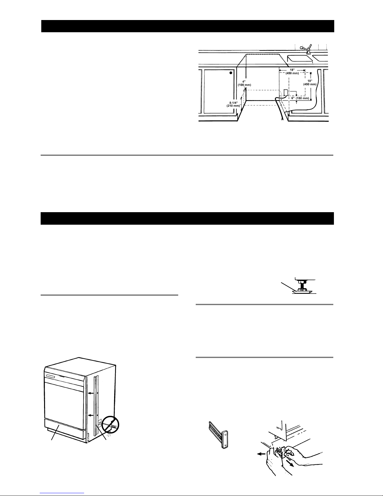
ADJUSTING THE DOOR SPRINGSADJUSTING THE DOOR SPRINGS
ADJUSTING THE DOOR SPRINGSADJUSTING THE DOOR SPRINGS
ADJUSTING THE DOOR SPRINGS
Afteryou install the custompanel,
make sure the door can be
opened at any angle. If it tends to
fall down, pull out the machine
and tension the door springs on
the sides of the machine by
moving them one hole farther
back or by twisting the spring to
make it shorter. If that doesn’t resolve the problem, you
mayneed to purchase theheavy-duty door springs (Part
Number 8071323-77).
FASTENING THE DISHWASHERFASTENING THE DISHWASHER
FASTENING THE DISHWASHERFASTENING THE DISHWASHER
FASTENING THE DISHWASHER
TO THE CABINETTO THE CABINET
TO THE CABINETTO THE CABINET
TO THE CABINET
Refer to page 8.
Installing the 1805FI Custom Panel
WARNING!
The custom panel must not
obstruct the turbo fan exhaust.
See step 4 above for instructions
on how to adjust the fan exhaust.
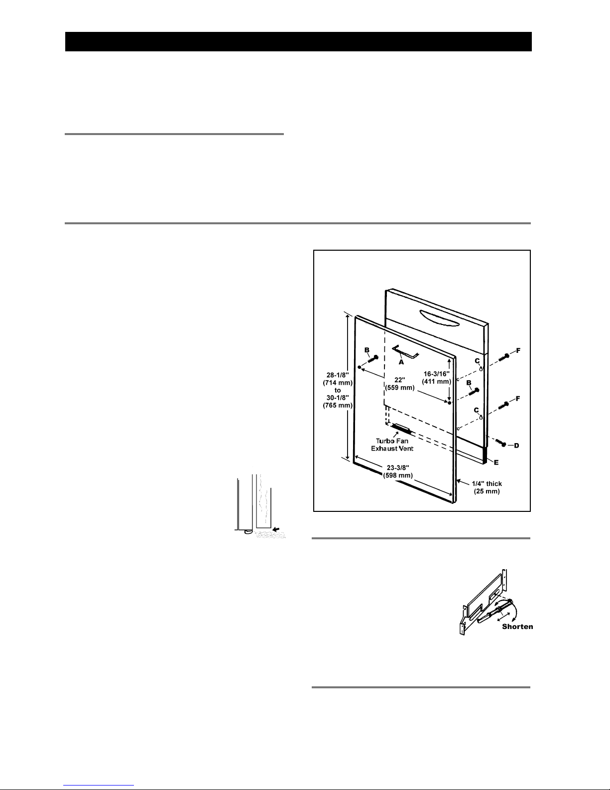
CUSTCUST
CUSTCUST
CUSTOM POM P
OM POM P
OM PANEL DIMENSIONSANEL DIMENSIONS
ANEL DIMENSIONSANEL DIMENSIONS
ANEL DIMENSIONS
Width: 23-3/8” (597 mm)
Height: 28-1/8”–30-1/8” (714 mm–765 mm)
(Measured from the top of the panel to
the lower edge of the kitchen cabinet.)
Thickness: 1/4” (25 mm)
Weight: Up to 22 lb.
NOTE:
Specifications subject to change without
notice.
NOTE:
Heavy-duty door springs can be purchased for
wooden door panels weighing over twelve
pounds. (P/N 8071323-77).
INSTINST
INSTINST
INSTALLINGALLING
ALLINGALLING
ALLING THE CUSTTHE CUST
THE CUSTTHE CUST
THE CUSTOM POM P
OM POM P
OM PANELANEL
ANELANEL
ANEL
Before fitting the custom panel, the dishwasher must
be installed underneath the cabinet. After you’ve made
the required measurements, pull the machine out again
to install the panel.
Refer to the illustration at right for instruction references.
1. Fit the handle (A) onto the panel according to the
manufacturer’s instructions. (
NOTE:
A handle
should be used rather than a knob, because a knob
does not provide enough grip.)
2. Peel the adhesive backing off the washers and place
them in line with the four keyholes (C) on the metal
front of the dishwasher door.
3. Loosen the screws (D) on the outer edges of the
dishwasher door.
4. Pull the turbo fan exhaust frame (E) down until the
loweredge aligns with the lower edge of the cabinets
and tighten the screws. Next, snap the plastic duct
into the turbo fan exhaust vent.
5. The two short screws (B) go into the back of the
panel, 16-3/16” from the upper edge of the panel
and 5/8” from the outer edges. Insert the short
screws into the panel, leaving 1/8” of space between
the screw head and the panel.
6. Hook the panel screws (F) into the keyholes (C) on
the dishwasher door.
7. Push the panel upwards until the lower edge aligns
with the lower edge of the cabinets.
NOTE:
The custom panel should not extend more
than 2-15/16” below the bottom of the dishwasher
door. Otherwise, it will strike the toe kick and
damage the machine and/or the panel.
8. Open the door and tighten the screws (F) inside.
9. Remove the backing from the protective tape and
apply it on the bottom edge of the panel, in front of
the exhaust vent.
FITTINGFITTING
FITTINGFITTING
FITTING THETHE
THETHE
THE 1805FI1805FI
1805FI1805FI
1805FI CUSTCUST
CUSTCUST
CUSTOM DOOR POM DOOR P
OM DOOR POM DOOR P
OM DOOR PANELANEL
ANELANEL
ANEL