Coster YHC 700 User manual

Network-Manager Modbus
YHC 700
Data Sheet
D33481-A 10/02/2020

Table of contents YHC 700
Table of contents
Warnings.....................................................................................................................4
1. General characteristics ..........................................................................................5
2. Technical specifications ........................................................................................5
2.1 Hardware..................................................................................................................................5
2.2 Mechanical features.................................................................................................................5
2.3 Electrical features.....................................................................................................................5
2.4 Supported devices ...................................................................................................................6
2.4.1 Devices on bus RS485 #1 (remote control)..........................................................................6
2.4.2 Devices on bus RS485 #2 (monitoring)................................................................................6
2.5 Accessories..............................................................................................................................6
3. Electrical installation..............................................................................................7
3.1 Electrical connections ..............................................................................................................7
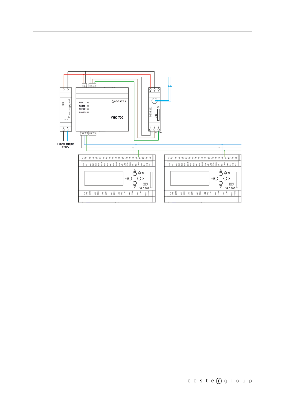
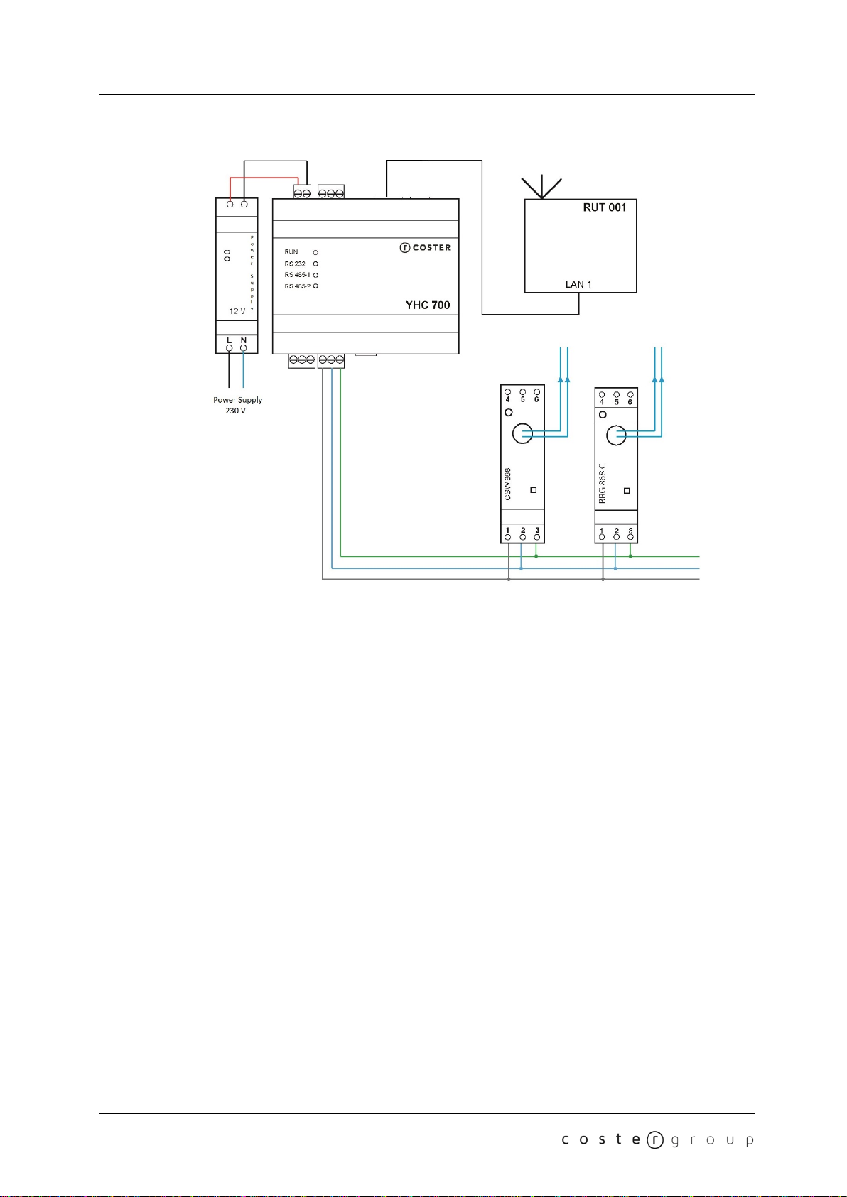
3.2 Connection examples...............................................................................................................8
4. LEDs......................................................................................................................12
5. Main features.........................................................................................................13
5.1 Communication with a supervisor..........................................................................................13
5.2 Communication with field devices..........................................................................................13
5.3 Bridging between YLC controllers..........................................................................................14
5.4 Data logging (instantaneous data logger)..............................................................................14
5.5 YLC data caching...................................................................................................................14
5.6 Sending alarms......................................................................................................................14
5.6.1 Sending alarms via e-mail...................................................................................................14
5.6.2 Sending alarms via HTTP/HTTPs.......................................................................................14
5.6.3 Sending alarms using the MDM 232 modem......................................................................15
5.7 Monitoring data reading .........................................................................................................15
5.8 Datalogging dei dati di monitoraggio......................................................................................15
5.9 M-BUS devices integration.....................................................................................................15
5.10 Sending data to the Cloud ...................................................................................................16
5.10.1 Sending data via the Ethernet port ...................................................................................16
5.10.2 Sending data to the cloud using the MDM 232 modem....................................................16
5.11 Sending date and time.........................................................................................................16
5.12 Software reset......................................................................................................................17
6. Remote management............................................................................................17
7. YHC Configuration................................................................................................17
7.1 Connecting to YHC ................................................................................................................17
2

YHC 700 Table of contents
7.1.1 Wi-fi connection...................................................................................................................18
7.1.2 Connection via USB cable ..................................................................................................18
7.1.3 Connection via Ethernet cable............................................................................................18
7.2 YHC Configuration.................................................................................................................19
7.2.1 Building Control...................................................................................................................19
7.2.2 Monitoring ...........................................................................................................................22
7.2.3 Settings ...............................................................................................................................26
8. Software update....................................................................................................29
8.1 Software update via FTP (remote update).............................................................................29
8.2 Aggiornamento software da locale.........................................................................................29
9. Commissioning.....................................................................................................30
9.1 Commissioning a control system (YHC)................................................................................30
9.1.1 Field devices commissioning ..............................................................................................30
9.1.2 YHC Configuration..............................................................................................................30
9.1.3 YLCs configuration on the software for remote management ............................................30
9.2 Commissioning a control system (YHC+MDM) .....................................................................31
9.2.1 Field devices commissioning ..............................................................................................31
9.2.2 YHC Configuration..............................................................................................................31
9.2.3 MDM 232 Configuration (to work with YHC).......................................................................31
9.2.4 YLCs configuration on the software for remote management ............................................32
9.3 Commissioning a monitoring system.....................................................................................33
9.2.1 Field devices commissioning ..............................................................................................33
9.3.2 YHC Configuration..............................................................................................................33
10. Diagnostics .........................................................................................................33
10.1 Home page...........................................................................................................................34
10.2 Diagnostics...........................................................................................................................34
11. Recommendations..............................................................................................35
12. Directives ............................................................................................................35
13. Regulations of conformity..................................................................................35
3

Warnings YHC 700
Warnings
The following instructions must be read and understood before installation, commissioning
and maintenance of the sensor.
WARNING!
YOUR SAFETY IS INVOLVED. A LACK OF FOLLOWING THESE
INSTRUCTIONS MAY ORIGINATE DANGER
The device must be installed by qualified personnel in accordance with
national regulations and/or related local requirements.
If the device is not installed, commissioned and maintained correctly according to the
instructions contained in this manual, then it may not work properly.
Failure to install, put into service and maintain the device in accordance to the instructions in
this manual can cause equipment faults and can cause hazards to the user and other
exposed persons
IMPORTANT!
BEFORE YOU START ANY WORK ON THE EQUIPMENT, SWITCH OFF THE
ELECTRICAL POWER SUPPLY.
FAILURE TO FOLLOW THESE INSTRUCTIONS CAN CAUSE INJURY TO PERSONS
OR DAMAGE TO THE EQUIPMENT.
4

YHC 700 1. General characteristics
1. General characteristics
The YHC700 (Y-help-communicator on platform 700) or NETWORK MANAGER MODBUS is
a device that optimizes the exchange of information and controls between YLC equipment.
It is able to manage and monitor field devices connected to it by means of an RS 485 bus or
an Ethernet port
YHC 700 manages three types of systems:
•Control systems with YLC 7xx-8xx
•Monitoring systems
•Hybrids (or Mixed) (control & monitoring) systems
In the first case, YHC 700 allows the system remote management and configuration either via
ethernet or via MDM 232.
In the second and third cases, the system remote management and configuration is supported
via ethernet only.
2. Technical specifications
The following tables show all the specifications relating to the device.
2.1 Hardware
N.
DESCRIPTION
1
RS-232 BUS (used for connection with the MDM 232 modem ONLY)
2
RS-485 EXPANSION BUS (1 for remote control devices, 1 for monitoring
devices)
1
Ethernet port (for communicating with the field and/or a supervisor)
1 micro-USB port
1
USB port
4
LEDs
microchip
ARM335x 1GHz ARM Cortex-A8
Ram 512MB DDR3
On-board Flash storage
4GB 8-bit eMMC
2.2 Mechanical features
Operating temperature range
0…+60 °C
Storage temperature range
-10…+80 °C
Weight
185 g
Size
6 DIN
90 x 105 x 71 mm (h x l x w)
2.3 Electrical features
Power Supply
12 Volt DC. (10 V DC. ~ 15 V DC.)
5

2. Technical specifications YHC 700
Maximum absorption 500 mA
Front panel degree of protection
IP 20
Back panel degree of protection
IP 20
2.4 Supported devices
2.4.1 Devices on bus RS485 #1 (remote control)
N.
DESCRIPTION
0.. 20 YLC (7xx e/o 8xx)
2.4.2 Devices on bus RS485 #2 (monitoring)
N.
DESCRIPTION
0..30
Multimeters of the following types: IME Nemo D4 Le (1-phase or 3-phase),
IME Conto D4 Pr MID, Electrex Atto D4 (1-phase or 3-phase), MFD 448
0..10
GSP 485
0..40
Heat meters among the following:
•M-BUS meters: Costergroup IEF 176, Costergroup IEF 276 e
Sensus PolluStat
•and/or Modbus meters: Isoil IFX F100
0..3
CSW 868
0..3
BRG 868 C
0..5
CDP 1x0 (M-Bus / Modbus converter for integrating up to 8 devices1)
2.5 Accessories
ALM 1210
DIN rail 12V-10W Power supply unit
1depending on the CDP model
6

YHC 700 3. Electrical installation
3. Electrical installation
Position the unit inside its electrical panel before you connect it up. The electrical equipment
must comply with current EU standards for cabling and installation; this device works only
with a 12V DC power supply.
3.1 Electrical connections
Installers are responsible for checking and ensuring that the type and the cross-section of the
cable used meet the requirements of their installations and that cabling conforms to current
national and local regulations.
If a cable is damaged, it must be replaced by the producer, the technical service or any other
person the-like.
WARNING: the RS 232 bus used to connect YHC to MDM 232 must be shorter than 3
meters.
WARNING: when connecting YHC to MDM, please make sure that the YHC TX terminal is
connected to the MDM TX terminal, and that the YHC RX terminal is connected to the MDM
RX terminal.
WARNING: use an RS 485 specific cable (ex: Belden 9841 or similar equivalent) to connect
the devices over each of the expansion bus.
7

3. Electrical installation YHC 700
3.2 Connection examples
Example 1: control system with multiple YLCs on the 485 bus and supervision via 3G modem
8

YHC 700 3. Electrical installation
Example 2: control system with multiple YLCs on the Ethernet bus (supervision via Ethernet)
Example 3: control system with multiple YLCs on the Ethernet bus and on the RS 485 bus
(supervised via Ethernet)
9

3. Electrical installation YHC 700
Example 4: monitoring system
10

YHC 700 3. Electrical installation
Example 5: hybrid system
NOTE: RUT 001 has been used in the above examples only for explanation purposes; any
generic router can be used.
WARNING: YLC 880 MUST be configured with RS 485 connectivity (see YLC 880 data
sheet).
11

4. LEDs YHC 700
4. LEDs
YHC700 is equipped with 4 signal LEDs:
●LED 1: power supply status (always ON)
●LED 2: communication on RS 232 port (blinks when transmitting/receiving)
●LED 3: communication on RS 485 port no. 1 (blinks when transmitting/receiving)
●LED 4: communication on RS 485 port no. 2 (blinks when transmitting/receiving)
12

YHC 700 5. Main features
5. Main features
5.1 Communication with a supervisor
YHC700 allows remote access to control installations with YLC controllers, to monitoring
installations and hybrid installations. Remote access is possible:
●Via routerRUT 002 connected to the Ethernet port of YHC700
●Via MDM 232 modem connected to YHC700 via bus 232.
In both cases, communication with the supervisor is via ModBus/RTU or Modbus/TCP-IP
protocol.
NOTE:
•Monitoring systems and hybrid systems (regulation + monitoring) communicate with a
supervisor only via ethernet.
•In order to use the ModBus/TCP-IP protocol to communicate with the supervisor,
please remember to specify - when configuring any YLC control unit - that the
protocol to use is ModBus/TCP-IP, indicating it in the Control Unit Access Code (see
chapter 9.1.3)
5.2 Communication with field devices
YHC700 can be connected to field devices via the RS485 bus or via its Ethernet port.
The RS485 bus connected to the RS485#1 port can only be used for control installations. On
this bus, YHC is master/slave and can communicate in Modbus/RTU or Modbus/TCP, at the
speed set during its configuration (the maximum communication speed allowed by YHC is
500kbps, but it can be lower, to consider the maximum speed supported by the connected
devices as well).
NOTE: from the FW version 2.0, YHC can communicate with YLC at two different baud rates:
9600 or 19200 (depending on the control unit settings2). YHC can also manage YLC with
different baud rates on the same control bus.
The RS485 bus connected to the RS485#2 port can only be used for energy monitoring
installations. On this bus, YHC is master and can only communicate in Modbus/RTU3(the
maximum communication speed allowed by YHC on this bus is 500kbps, but it can be lower,
to consider the maximum speed supported by the connected devices as well).
In addition to supervision, the Ethernet port can also be used for control, connecting YLC
controllers by means of STE000 converters. In this case, communication with the controllers
takes place using the Modbus/IP and the communication with the supervisor can only take
place via Ethernet.
NOTE:
•YHC default Modbus address is 250.
•YHC can be configured to be port 485 terminator for both RS485 buses.
2Only for YLC control units with FW version equal to or greater than 730.00.001
3In the case of GSP 485 devices only, a proprietary protocol is used (custom version of Modbus/RTU).
13

5. Main features YHC 700
5.3 Bridging between YLC controllers
YHC700 manages the data exchange between YLC controllers, using the same mechanism
currently provided for and used by GSM 485..
5.4 Data logging (instantaneous data logger)
YHC can periodically:
•Send commands for reading the data from the connected control units
•Send them (via https) to a configured address (see chapter 5.6)
This service is called instantaneous data logging and can be activated during the YHC
configuration (see chapter 7.2.1)
ATTENTION: the instantaneous datalogger service is based on the periodic YLC polling
performed by YHC. Since this periodic reading can be disabled, please make sure it is
enabled before activating the instantaneous datalogging service.
5.5 YLC data caching
The data periodically read by the YLC control units can be cached and updated at each
reading. In this way, if a supervisor requests the control unit data, YHC can send it
immediately.
From FW 2.0,YLC data caching can be disabled.
5.6 Sending alarms
In control systems and hybrid systems4, you can decide to manage YLC alarms through the
YHC700.
YHC700 can send alarms only via its ethernet port, in two possible ways:
•via e-mail
•via HTTP/HTTPs post command
When configuring YHC700, you can specify which of the two modes you want to enable (you
can also enable both of them).
5.6.1 Sending alarms via e-mail
In the case of sending by e-mail you can specify:
●The email sending service used (you can choose between: ClimatelCloud or an
SMTP server with SSL or STARTTLS authentication). Default: ClimatelCloud
●A description of the sender
●Sender's email address (and password for authentication on the SMTP service used
for sending)
●Up to 5 email recipients of alarm emails
5.6.2 Sending alarms via HTTP/HTTPs
In the case of sending via HTTP post you can specify:
●The address of the server to send the alarm to
●The key to bind the data received to the plant they refer to.
4For the Control part of the hybrid system
14

YHC 700 5. Main features
NOTE: The message sent via HTTP/HTTPs POST is in a predefined JSON format; the
destination server must therefore be able to interpret it.
5.6.3 Sending alarms using the MDM 232 modem
In control systems where an MDM 232 modem is used with the YHC700, it is possible to
select that the modem will manage alarms sending instead of the YHC700.
Should the modem be chosen to send alarms, the configuration parameters can only be set
via the mimic panel of the MDM 232 modem. Moreover, in this case, alarms and can be sent:
●by email
●by http post
●via text message
In the case of sending by email you can specify:
●The email sending service used (you can choose between: ClimatelCloud or an
SMTP server WITHOUT authentication). Default: ClimatelCloud
●A description of the sender
●Sender's email address
●Up to 3 email recipients of alarm emails
In the case of sending via HTTP/HTTPs post you can specify:
●The address of the server to send the alarm to
●The key to bind the data received to the plant they refer to.
In the case of sending by SMS you can specify:
●Up to 3 numbers of SMS recipients
5.7 Monitoring data reading
In the case of energy monitoring systems, YHC700 periodically queries the devices in the
field; the acquisition periodicity can be selected during the configuration phase, for each of the
supported device types.
The acquired data can then be consulted:
●through a supervisor interface (if the option to send data to the supervisor has been
enabled)
●through the YHC Diagnostics pages (see chapter 10)
5.8 Datalogging dei dati di monitoraggio
From release 2.0 of YHC it is possible to enable the logging service of data acquired from
energy monitoring devices. Logged data can be exported on USB stick or on SFTP server on
YHC (for subsequent download on PC)
NOTE: for the datalogger records to contain valid dates, the date and time must have been
set at least once on YHC (and, in any case, after each device restart). Refer to chapter 7.2.1.1
for details on how to set the date and time on YHC in the presence and absence of Internet
access.
5.9 M-BUS devices integration
From version 2.0, YHC also supports the management of M-BUS heat meters, integrated
through the CPD device. The integration of M-BUS metering units is made through the
following steps:
15

5. Main features YHC 700
●Configure the CDP device as described in the Configuration guide (available on the
Company website)
●Export the CSV file containing the configuration data just set up
●Add the M-BUS gateway and subsequently configure each heat meter through the
appropriate YHC page (see chapters 7.2.2.2 and 7.2.2.1.4)
NOTE: YHC is able to integrate up to 5 M-BUS gateways and up to 40 heat meters, either
Modbus type (connected directly on the monitoring bus or integrated through BRG 868
C/BRG 868 devices) or M-BUS type (integrated through CDP device).
5.10 Sending data to the Cloud
5.10.1 Sending data via the Ethernet port
YHC700 can periodically send the data acquired by the devices connected to it to one or more
servers in cloud.
Data are sent via HTTP/HTTPs and are in a predefined JSON format, within which there is a
section for each type of device in the system. Each section is delimited by a key to allow the
destination server to understand which device the data refers to. The destination server must
be able to interpret this format.
The data sent are:
●in the case of devices on energy monitoring installations, the data acquired by the
devices in the field (similarly to what was done by GTW 485)
●in case YHC700 is connected to YLC controllers, the data sent are those of the
instantaneous data logger
It is possible to send data to different cloud servers (for example, you could send YLC data to
one server and those of the wireless sensors to another), specifying for each also the
periodicity of the sending (which is totally independent from the periodicity with which YHC700
retrieves data from the field).
5.10.2 Sending data to the cloud using the MDM 232 modem
As for alarms sending, when and MDM 232 modem is used together with the YHC700, during
YCH 700 configuration it is possible to select that the former for managing data sending to
cloud instead of the latter.
Should you choose the modem to send data to the cloud, the configuration parameters can
only be set via the mimic panel of the MDM 232 modem.
It is possible to send the data to a cloud server specifying the type of service, the server URL,
the periodicity of the sending and the cloud key necessary to identify, in the JSON file sent by
YHC700, the data section relating to the YLC controllers.
5.11 Sending date and time
YHC700 can send date and time to the connected devices (for instance, the CSW 868). To
ensure that this functionality works as expected, YHC must be properly configured to
synchronise its date & time (see chapter 7).
16

YHC 700 6. Remote management
5.12 Software reset
From version 2.0 it is possible to restart the device SW from YHC 700 configuration pages.
This operation can be useful in case of problems or when the YLC baudrate has been
changed after the first configuration (in this case, YHV 700 SW must be restarted to detect the
new baudrate).
6. Remote management
Remote management and supervision through YHC 700 can be carried out in different ways,
depending on the type of system we want to manage/supervise.
Control systems can be:
●remotely managed with ClimaOffice/WEBGarage
●remotely supervised or any software able to:
○send ModBus commands to read the YLC in field
○manage the data received from the YHC via HTTP/HTTPs
Monitoring systems can only be supervised, through:
●YHC web pages (see chapter 10)
●WEBGarage or any software able to:
○send ModBus commands to read the YLCs in field
○manage the data received from the YHC via HTTP/HTTPs
7. YHC Configuration
YHC 700 can be configured using the HTML pages it provides.
7.1 Connecting to YHC
To configure YHC 700 via HTML pages, first of all you must connect to YHC700 in one of the
following ways:
•Wi-Fi connection (via certified Wi-Fi USB dongle)
•Connection via USB cable
•Connection via Ethernet cable
17

7. YHC Configuration YHC 700
7.1.1 Wi-fi connection
1. Connect the USB Wi-Fi dongle to the USB port of YHC
2. Connect the PC to the Wi-Fi network with SSID "yhc700" (password: costergroup)
3. From a web browser open the YLC URL:
<indirizzo ip dell’yhc>:8080
(default: http://192.168.64.2:8080)
4. Access the configuration pages
NOTE: you must use a USB dongle with the following features: WLAN USB 300 mbit/s with
64/128-bit encoding / WPA/WPA2 / WPA-PSK/WPA2-PSK, USB 2.0 interface compatible with
USB 1.1 / upward compatible with USB 3.0 | frequency range: 2.4 GHz, 13 channels, mime
technology / MIMO. Contact the Cost Group technical assistance for further information.
7.1.2 Connection via USB cable
1. Connect the PC to YHC with a USB cable (USB to micro-USB)
2. From a web browser open the YHC URL:
<indirizzo ip dell’yhc>:8080
(default: http://192.168.7.2:8080)
3. Access the configuration pages
7.1.3 Connection via Ethernet cable
1. Configure the PC with a static address belonging to subnet where YHC is installed
2. Connect the PC to YHC with an Ethernet cable
3. From a web browser open the YHC URL:
18

YHC 700 7. YHC Configuration
<indirizzo ip dell’yhc>:8080
(default: http://192.168.63.2:8080)
4. Access the configuration pages
NOTE: To configure YHC 700, an Internet connection is NOT required.
7.2 YHC Configuration
Once connected to the device, you can configure YHC using the HTML pages as shown
below:
NOTE: to access the Configuration pages, you must be logged in with the following
credentials:
username: service
password: CosterGrp267837
The password can be changed in a dedicated menu of the YHC WEB Pages (see chapter
7.2.3.6).
7.2.1 Building Control
This menu provides access to the WEB pages for configuring the YLCs and how to manage
their alarms and their data sending to the cloud:
19

7. YHC Configuration YHC 700
7.2.1.1 YLC configuration
You can use this page to specify:
●How many controllers are connected to YHC700 (up to 20). Default: 0
●The communication protocol used for data exchange with these controllers. Default:
ModBus/RTU
●If the YHC function of data exchange between controllers is enabled or not. Default:
Disabled
●If alarm reading is enabled or not. Default: Disabled
●Whether the YLC data caching is enabled or not. Default: Disabled
●For each controller, you can specify:
○Whether it is enabled or not (this can be useful in the support phase, to
isolate any source of errors)
○The connection mode (RS485 bus or Ethernet5). Default: RS 485
○The Modbus address (Default: 1)
○The IP address, if any (if the specified connection mode is Ethernet).
oWhether the instantaneous data logger cloud sending is enabled on that
controller. Default: No
○A short description (used in the diagnostic web pages)
NOTE: Modbus address and communication protocol must be the same as those set on YLC;
The selected communication protocol must necessarily be used also for ClimaOffice
connections (YHC does not perform protocol conversions)
5Used to support the existing installations where YLC is connected to STE000.
20
Table of contents
Popular Network Hardware manuals by other brands

Panasonic
Panasonic Photo IC PNA4601M Specifications

Omnitron Systems Technology
Omnitron Systems Technology iConverter Gx AN quick start guide

Ascentic
Ascentic 39-GMHDPH manual

Memotec
Memotec CX800 Hardware reference manual

RAK
RAK RAK11200 quick start guide

Patton electronics
Patton electronics DigiLink-V 2530 user manual