COULTER LH 700 Series Quick guide

LH 700 Series
Workstation Configuration
P/N: 9023736
Revision B
Approved: March 25, 2002
Author: Jack Wojciechowski
These drawings and specifications are the property of Beckman Coulter Inc., are issued in strict
confidence, and shall not be reproduced, copied, or used as the basis for the manufacture or sale of
apparatus, without prior written permission.
NEC MultiSync LCD 1700m+


LH 700 Series Workstation Configuration
P/N: 9023736
March 25, 2002 Page
3
Document Approval
Name Signature Title Approval Function
Ian Burgess CPDM Approval Project Manager Manager: Software
Doug Dunbabin CPDM Approval Staff Applications Engineer Manager: Technical Support
Don Meadows CPDM Approval Staff Applications Engineer Manager: Technical Support
Jack Wojciechowski CPDM Approval Applications Engineer Originator
Jack Wojciechowski CPDM Approval Applications Engineer R & D Service
Steve Simmons CPDM Approval Sr. Staff Quality Assurance Engineer Quality Assurance

LH 700 Series Workstation Configuration
P/N: 9023736
March 25, 2002 Page
4
TABLE OF CONTENTS
LH 700 Series Workstation Configuration ..................................................... 10
1. Introduction .................................................................................................................. 10
1.1. Document Layout ..................................................................................................................................... 10
1.2. Scope ....................................................................................................................................................... 10
1.3. Function.................................................................................................................................................... 10
1.4. Operating Environment ............................................................................................................................ 10
1.5. Transporting ............................................................................................................................................. 11
1.6. Safety Precautions and General Service Information ..............................................................................11
1.7. Hazard Conventions................................................................................................................................. 12
1.8. Definition of Acronyms and Terms........................................................................................................... 12
COMPONENT DESCRIPTION AND CONFIGURATIONS ................................ 15
Circuit Cards.................................................................................................... 15
2. System card (Motherboard)......................................................................................... 15
2.1. Intel Desktop Board D815EEA................................................................................................................. 16
2.1.1. Input and Output Connections...................................................................................................... 16
2.1.2. Jumper Settings ........................................................................................................................... 16
2.2. AMI Olympus II ( Series 821 ) .................................................................................................................. 18
2.2.1. Input and Output Connections...................................................................................................... 18
2.2.2. JP4 Front Panel Connector .......................................................................................................... 19
3. Video Card .................................................................................................................... 21
3.1. Matrox®G550 Dual-DVI AGP Video Card................................................................................................ 22
3.1.1. Input and Output Connections...................................................................................................... 22
3.1.2. Matrox G550 AGP Video Card Software Installation and Configuration ...................................... 23
4. Modem Card ................................................................................................................. 24
4.1. US Robotics 56Kb Card – Model 3CP5610A ........................................................................................... 25
4.1.1. Input and Output Connections...................................................................................................... 25
4.1.2. US Robotics 3CP5610A 56KB Card Software Installation and Configuration.............................. 25
5. Multi-port Serial Card(s) .............................................................................................. 26
5.1. Equinox SST-4/8P Multiport Serial Card .................................................................................................. 27
5.1.1. Input and Output Connections...................................................................................................... 27
5.1.2. Equinox SST-4/8P Card Software Installation............................................................................. 27
6. SCSI Interface Card(s) ................................................................................................. 28
6.1. Adaptec 2930U......................................................................................................................................... 29
6.1.1. Input and Output Connections...................................................................................................... 29
6.1.2. Adaptec 2930U Card Installation and Software configuration...................................................... 29
INTERNAL DRIVES .......................................................................................... 30
7. Floppy Drive ................................................................................................................. 30
7.1. Sony 3 1/2 Floppy Drive ........................................................................................................................... 31
7.1.1. Input and Output Connections...................................................................................................... 31
8. Hard Drive..................................................................................................................... 32

LH 700 Series Workstation Configuration
P/N: 9023736
March 25, 2002 Page
5
8.1. Quantum Fireball Plus AS Hard Drive...................................................................................................... 33
8.1.1. Input and Output Connections...................................................................................................... 33
8.1.2. Jumper Settings ........................................................................................................................... 33
8.2. Maxtor DiamondMaxPlus D740X Hard Drive.......................................................................................... 34
8.2.1. Input and Output Connections...................................................................................................... 34
8.2.2. Jumper Settings ........................................................................................................................... 34
9. CD/DVD Drive ............................................................................................................... 35
9.1. Toshiba DVD-ROM SD-M1402 ................................................................................................................ 36
9.1.1. Input and Output Connections...................................................................................................... 36
9.2. Yamaha 2200EZ CD-R/W Drive ............................................................................................................. 37
9.2.1. Input and Output Connections...................................................................................................... 37
PERIPHERALS ................................................................................................. 38
10. Monitor.......................................................................................................................... 38
10.1. NEC Multisync LCD 1700M+................................................................................................................ 39
10.1.1. Input and Output Connections...................................................................................................... 39
10.1.2. Software Settings ......................................................................................................................... 39
10.1.3. Monitor Settings ........................................................................................................................... 40
11. Barcode Reader ( Handheld )...................................................................................... 42
11.1. Welch Allen IT3800 Barcode Scanner ................................................................................................. 42
11.1.1. Input and Output Connections...................................................................................................... 42
11.1.2. Hardware Configuration ............................................................................................................... 42
11.1.3. Software Configuration................................................................................................................ 42
12. Uninterruptible Power Supplies (UPS)....................................................................... 45
12.1. APC Back-UPS® 650........................................................................................................................... 45
12.1.1. Connect Battery............................................................................................................................ 45
12.1.2. APC Back-UPS 650 Hardware Setup .......................................................................................... 45
12.1.3. APC Back-UPS 650 Software Configuration................................................................................ 46
13. Iomega® Jaz® Drive .................................................................................................... 49
13.1. Setup .................................................................................................................................................... 49
SOFTWARE ...................................................................................................... 50
14. BIOS .............................................................................................................................. 50
14.1. Intel BIOS used with the D815EEA System Board .............................................................................. 51
14.1.1. Accessing the BIOS setup ........................................................................................................... 51
14.1.2. BIOS Setup .................................................................................................................................. 51
14.1.3. Main tab........................................................................................................................................ 51
14.1.4. Advanced tab ............................................................................................................................... 52
14.1.5. Security ........................................................................................................................................ 54
14.1.6. Power ........................................................................................................................................... 55
14.1.7. Boot .............................................................................................................................................. 55
14.1.8. Exit ............................................................................................................................................... 55
14.2. AMI BIOS use with the AMI Olympus (Series 821) System Board ...................................................... 56
14.2.1. Accessing the BIOS setup ........................................................................................................... 56
14.2.2. BIOS Setup .................................................................................................................................. 56
14.2.3. Main tab........................................................................................................................................ 56
14.2.4. Advanced tab ............................................................................................................................... 57
14.2.5. Chipset ......................................................................................................................................... 63
14.2.6. PCIPnP......................................................................................................................................... 64
14.2.7. Power ........................................................................................................................................... 64
14.2.8. Boot .............................................................................................................................................. 65

LH 700 Series Workstation Configuration
P/N: 9023736
March 25, 2002 Page
6
14.2.9. Security ........................................................................................................................................ 65
14.2.10. Exit .............................................................................................................................................. 66
15. Operating System ........................................................................................................ 67
15.1. MicrosoftWindows 2000Professional........................................................................................... 67
15.1.1. Overview ...................................................................................................................................... 67
15.1.2. Control Panel................................................................................................................................ 67
15.1.3. Printers ......................................................................................................................................... 70
15.1.4. Administrative Tools..................................................................................................................... 72
15.1.5. Additional Programs and Service Functions ................................................................................ 75
16. LH 700 Series Workstation Application ..................................................................... 77
16.1. LH 700 Series Workstation Imaging Procedure................................................................................... 77
16.1.1. Parts Required ............................................................................................................................. 77
16.1.2. Procedure..................................................................................................................................... 77
16.2. LH 700 Series Workstation Update Procedure .................................................................................... 80
16.2.1. Parts Required ............................................................................................................................. 80
16.2.2. Procedure..................................................................................................................................... 80
16.3. Save and Restore Configuration .......................................................................................................... 80
16.3.1. Save Configuration....................................................................................................................... 80
16.3.2. Restore Configuration .................................................................................................................. 81
16.4. Archive ( Save ) Complete Database................................................................................................... 82
16.5. Restore................................................................................................................................................. 83
16.5.1. Registry ........................................................................................................................................ 83
16.5.2. Database ...................................................................................................................................... 84
16.5.3. List Mode Data ............................................................................................................................. 84
16.6. SlideMaker Software Download ........................................................................................................... 85
16.7. SlideStainer Software Download.......................................................................................................... 86
17. Support Software ......................................................................................................... 87
17.1. pcAnyWhere......................................................................................................................................... 87
17.2. Norton AntiVirus ................................................................................................................................... 89
18. Online Intelligent Service - Remote Diagnostics....................................................... 90
18.1. Remote Access and Remote Control ( RCS )...................................................................................... 90
18.1.1. Requirements............................................................................................................................... 90
18.1.2. Procedure – Instrument Workstation ........................................................................................... 90
18.1.3. Remote Computer Setup ............................................................................................................. 91
18.1.4. Procedure – Remote .................................................................................................................... 91
18.2. Workstation Initiated Diagnostics with Internet Access........................................................................ 92
19. LH 700 Series Workstation Installation procedure ................................................... 93
19.1. Workstation Components:.................................................................................................................... 93
19.1.1. Monitor including: ......................................................................................................................... 93
19.1.2. Computer base including: ............................................................................................................ 93
19.1.3. UPS including:.............................................................................................................................. 93
19.1.4. Optional accessories:................................................................................................................... 93
19.2. Installation Requirements..................................................................................................................... 93
19.3. Unpacking ............................................................................................................................................ 94
19.4. Voltage Configuration........................................................................................................................... 94
19.5. Cable Connections ............................................................................................................................... 94
19.6. Configuration and Verification .............................................................................................................. 95
VERIFICATION PROCEDURES ....................................................................... 99
20. Verification Procedures............................................................................................... 99
20.1. LH 700 Series Workstation Functional Verification.............................................................................. 99
20.2. LH 700 Series Workstation Hardware Verification............................................................................. 100

LH 700 Series Workstation Configuration
P/N: 9023736
March 25, 2002 Page
7
20.3. Display Verification............................................................................................................................. 101
20.4. Host Interface Communication Verification........................................................................................ 102
20.5. Remote Diagnostics Verification ........................................................................................................ 103
20.6. UPS Verification ................................................................................................................................. 104
20.7. LH 700 Series Workstation to Analytical Station Communication Verification................................... 105
MAINTENANCE AND TROUBLESHOOTING................................................. 106
21. Replacement Procedures .......................................................................................... 106
22. Maintenance ............................................................................................................... 107
22.1. Barcode Scanner................................................................................................................................ 107
22.2. Computer Base .................................................................................................................................. 107
22.3. Monitor ............................................................................................................................................... 107
22.4. Keyboard ............................................................................................................................................ 107
22.5. Mouse................................................................................................................................................. 107
23. Troubleshooting......................................................................................................... 108
23.1. Passwords.......................................................................................................................................... 108
23.2. Troubleshooting Problems During Power On Self Test (POST) ........................................................ 108
23.3. LH 700 Series Workstation Does Not Boot and No Errors are Displayed ......................................... 110
23.4. Troubleshooting RCS......................................................................................................................... 113
23.4.1. Dial Tone is Not Audible............................................................................................................. 113
23.4.2. Dial Tone is Audible ................................................................................................................... 113
23.5. Troubleshooting Errors While Operating the LH 700 Series Workstation Installation ....................... 114
QUICK REFERENCE...................................................................................... 115
24. Quick Reference......................................................................................................... 115
24.1. Part Numbers ..................................................................................................................................... 115
24.1.1. LH 700 Series Workstation Components................................................................................... 115
24.2. Configuration Summary ..................................................................................................................... 117

LH 700 Series Workstation Configuration
P/N: 9023736
March 25, 2002 Page
8
TABLES
Table 1-1: Acronyms and Terms Used in this Document ___________________________________________ 12
Table 2-1: System Card(s) Configuration _______________________________________________________ 15
Table 2-2: Circuit Card Locations on the Intel Desktop Board D815EEA _______________________________ 16
Table 2-3: J7C1 - Bios Setup Configuration Jumper Settings ____________________________________ 17
Table 2-4: Connector and Circuit Card Locations on AMI Olymus II __________________________________ 18
Table 2-5: J7C1 - Bios Setup Configuration Jumper Settings ____________________________________ 19
Table 3-1: Video Card Configuration___________________________________________________________ 21
Table 4-1: Modem Card Configuration _________________________________________________________ 24
Table 5-1: Multi-port Serial Card(s) Configuration ________________________________________________ 26
Table 6-1: SCSI Interface Card Configuration ___________________________________________________ 28
Table 7-1: Floppy Drive(s) Configuration _______________________________________________________ 30
Table 8-1: Hard Drive(s) Configuration _________________________________________________________ 32
Table 9-1: CD-ROM Drive(s) Configuration _____________________________________________________ 35
Table 10-1: LH 700 Series Workstation Monitors _________________________________________________ 38
Table 10-2: Onscreen Menu Function for NEC MultiSync LCD 1700M+ _______________________________ 40
Table 11.1-1: Default Welch Allen IT3800 Barcode Scanner Configuration _____________________________ 42
Table 11.1-2: Configuration Options for the Welch Allen IT3800 Barcode Scanner _______________________ 43
Table 23.1-1: Pre-Assigned LH 700 Series Workstation Passwords__________________________________ 108
Table 23.2-1: D815EEA BIOS Beep Codes_____________________________________________________ 108
Table 23.2-2: D815EEA BIOS LED Codes ____________________________________________________ 109
Table 23.2-3: D815EEA POST Error Messages_________________________________________________ 109
Table 23.3-1: System Does Not Boot and Fan is Off _____________________________________________ 111
Table 23.3-2: System Does Not Boot and Fan is ON _____________________________________________ 111
Table 23.4-1: RCS Connection Failure -- No Dial Tone ___________________________________________ 113
Table 23.4-2: RCS Connection Failure with Dial Tone ____________________________________________ 113
Table 24.1-1: Part Numbers ________________________________________________________________ 115
Table 24.2-1: Hardware Configurations of the LH 700 Series Workstation _____________________________ 117
Table 24.2-2: Software Configurations of the LH 700 Series Workstation _____________________________ 117

LH 700 Series Workstation Configuration
P/N: 9023736
March 25, 2002 Page
9
FIGURES
Figure 2-1: Intel Desktop Board D815EEA ______________________________________________________ 17
Figure 2-2: AMI Olympus II – Series 821 _______________________________________________________ 19
Figure 3-1: Mattrox G550 AGP Video Card _____________________________________________________ 22
Figure 4-1: US Robotics 3CP5610A 56K Pro Modem Card_________________________________________ 25
Figure 5-1: Equinox SST-4/8P Multiport Serial Card ______________________________________________ 27
Figure 6-1: Adaptec AHA-2930CU Card ________________________________________________________ 29
Figure 7-1: TEAC FD-235HF 3 1/2 Floppy Drive Hardware Configuration ______________________________ 31
Figure 8-1: Quantum Fireball Plus AS Hard Drive Hardware Configuration _____________________________ 33
Figure 9-1: Toshiba SD-M1402 DVD-ROM Hardware Configuration __________________________________ 36
Figure 9-2: Yamaha 2200EZ CD-R/W __________________________________________________________ 37
Figure 10-1: NEC Multisync LCD 1700M+ - Rear View ____________________________________________ 39
Figure 10-2: NEC MultiSync LCD 1700M+ Controls _______________________________________________ 40
Figure 12-1: Power Options Properties_________________________________________________________ 47
Figure 12-2: UPS Selection dialog Box _________________________________________________________ 47
Figure 12-3: UPS Configuration dialog box ______________________________________________________ 48
Figure 15-1: Control Panel _________________________________________________________________ 67
Figure 15-2: Date & Time Dialog Box __________________________________________________________ 68
Figure 15-3: Regional Options _______________________________________________________________ 69
Figure 15-4: Select System Locale dialog_______________________________________________________ 70
Figure 15-5: Administrative Tools _____________________________________________________________ 73
Figure 15-6: Computer Management Screen – Disk Management Selected ___________________________ 74
Figure 19-1: LH 700 Series Workstation Cable Connections ________________________________________ 97

LH 700 Series Workstation Configuration
P/N: 9023736
March 25, 2002 Page
10
LH 700 Series Workstation Configuration
1. INTRODUCTION
1.1. Document Layout
This document is divided into sections specific to a model or version of a component in order to
minimize documentation update changes. This layout allows for change pages to be inserted
without affecting other sections. The layout also provides that all component information can be
retained when new information is added. This will enable users of this document to have access
to all versions of the LH 700 Series Workstation in one complete document.
1.2. Scope
The intention of this document is to provide very specific guidelines for configuration of the LH 700
Series Workstation. The use of incorrect settings may render the system unstable and make
troubleshooting intermittent problems extremely difficult. This document includes replacement and
configuration procedures that not intended to be used for routine service on the LH 700 Series
Workstation. This manual does not cover the LH 700 Series Workstation Application.
It is intended that users of this manual should have achieved, at a minimum, LH 700 Series
Service Certification.
CAUTION: The use of incorrect settings can make the system perform in an unpredictable
manner. It is possible to complete configuration of some components or software using settings
other than the settings detailed in this manual. This can make future system upgrades or repairs
to the system extremely difficult due to hardware and/or software conflicts. Any deviations from
the settings specified in this document will also make troubleshooting and identifying intermittent
problems extremely difficult.
ATTENTION: This document is intended to supply configuration information to assist experienced
service personnel for repair of the LH 700 Series Workstation. This manual is not intended to
provide the necessary technical capabilities and know-how in order to properly troubleshoot and
repair a LH 700 Series Workstation. Beckman Coulter Inc. assumes no liability whatsoever for any
personal injury or property damage resulting from maintenance and/or repair performed by
persons not employed by Beckman Coulter Inc..
1.3. Function
The LH 700 Series Workstation is a combination of hardware and the LH 700 Series Installation
software, which provides a customer interface with data gathered on the LH 700 Series Analytical
Station(s). The LH 700 Series Installation also provides:
• Quality control analysis
• Verification and troubleshooting functions
• An interface to host computer(s)
• A CD-ROM based online customer manual
• A CD-ROM based online service manual
• Network printer capability
• Remote diagnostic capabilities
1.4. Operating Environment

LH 700 Series Workstation Configuration
P/N: 9023736
March 25, 2002 Page
11
To ensure that the LH 700 Series Workstation has the highest reliability, it should be placed in an
area with good ventilation, low humidity, out of direct sunlight and away from heat sources. The
rear cooling fan opening must allow for an unobstructed flow of air to ensure that the system does
not overheat. Refer to Section LH 700 Series Workstation, for specifications.
1.5. Transporting
Always perform a Shutdown and power Off the LH 700 Series Workstation before moving it. Any
sudden jar or shock may permanently damage the hard drive. Hard drives are more resistant to
shock when they are shutdown.
If the LH 700 Series Workstation will be transported over a distance, the original packing (or
enough padding as reasonably possible) should be used to protect the LH 700 Series Workstation
from excessive vibration or shock.
1.6. Safety Precautions and General Service Information
1. Connecting or disconnecting cables with the power ON can result in injury from an electronic
shock. This will also cause electrical spikes that can damage electronic components. This
damage may cause immediate problems, intermittent problems, or cumulative damage that
shortens the life of the component. When completing any procedures that require
disconnecting cables to the computer base, make sure the power is OFF.
2. Standard laboratory procedures should be followed during the operation and/or servicing of
the LH 700 Series Workstation. These practices include, but are not limited to, use of barrier
protection, such as protective gloves, protective eye wear, and suitable laboratory attire.
3. Never remove any covers without making sure the power is OFF and the power source is
disconnected. The computer base and monitor contain high voltages that can cause injury or
death.
4. Even a small electrostatic discharge can damage circuit cards, RAM memory or the CPU. A
damaged component might not fail immediately, but over time it will become worse and
possibly cause an intermittent problem. Be very careful to handle cards only by the edges. Do
NOT touch the gold/silver edge-connectors or any of the components on the board. Leave
components in their anti-static bag until ready for installation. ALWAYS wear a ground strap
when handling computer components.
5. Always SHUTDOWN and POWER OFF the LH 700 Series Workstation before moving it. Any
sudden jar or shock may permanently damage the hard drive resulting in loss of all data.
Hard drives are more resistant to shock if they are shut down
6. Never spray or pour cleaners directly on the computer base or monitor. Any fluid that runs
inside the monitor or computer base may result in injury from an electronic shock or cause an
electrical short, resulting in electrical damage to the hardware.

LH 700 Series Workstation Configuration
P/N: 9023736
March 25, 2002 Page
12
1.7. Hazard Conventions
WARNING May Cause Injury
CAUTION Might Cause Damage to the Instrument or Software Structure
IMPORTANT May cause improper instrument operation or wrong results
NOTE Additional information
ATTENTION Critical Information required for completion of a procedure.
1.8. Definition of Acronyms and Terms
Table 1-1: Acronyms and Terms Used in this Document
Term Definition
+
Used to show keys that must be pressed simultaneously. (i.e., Press
<CTRL>+<ALT>+<DEL>)
+( Plus ) This is used to indicate the upper level of a structure containing many items or
options. Choosing, or clicking this icon will expand the upper level structure to
display or select the lower level. It is often used in a Windows 2000 tree view.
<> Used to enclose the name of a key on the keyboard.
ac Alternating Current. This is used to refer to the voltage at the wall outlet: either
220V or 110V ac.
AGP Accelerated Graphics Port. This technology provides a port between the graphics
controller and system RAM. Video data can be sent directly to system RAM at a
fast rate, rather than being cached in the video RAM, and then transferred.
Analog Telephone A standard voice telephone. This type of telephone works with analog telephone
lines that are also compatible with modems. These are different than the
telephones used in large office or hospital telephone systems that use a high
voltage digital signal.
Application A software program that operates in combination with an operating system to
perform a specific task.
Boot To start the computer system and load the operating system.
Bus A collection of signal lines. The specification of a bus defines the purpose of each
line and the timing relationship of the electrical signals.
CD-ROM ( sometimes
referred to as CD )
Compact Disk-Read Only Memory. This type of media allows up to 650MB of data
access but cannot be used to save data.
Choose Pick an item that begins an action (including menu commands, icons and
buttons). The option to choose will be capitalized (i.e., choose OK).
Click This means to move the mouse cursor or pointer above the desired choice or icon
and pressing the left mouse button. When the right mouse button press is
desired, this will be spelled out more completely as ‘right click’.
Close
During software procedures this refers to ending an open window or application.
CMOS Complementary Metal Oxide Semiconductor. A logic circuit family that uses very
little power.
Computer Base The computer case including the system card or motherboard, drives, circuit
cards, and computer power supply.
Configuration The hardware and software settings that allow different hardware and software
components of a computer system to communicate.
CPU Central Processing Unit. The integrated chip that performs computing functions of
the computer.
DVD-ROM ( usually
referred to as DVD )
Digital Versatile Media. DVD-ROM is read only but can store much more
information than CD-ROM. The basic single sided, single layer DVD-ROM holds
4.38 GB. A double sided, double layer DVD-ROM holds 15.9 GB.

LH 700 Series Workstation Configuration
P/N: 9023736
March 25, 2002 Page
13
Term Definition
EIDE Enhanced Intelligent Drive Electronics. An interface specification for drives.
Enter Type the exact characters that are shown in quotes.
LH 700 Series Analytical
Station
The CoulterLH 700 Series Diluter, Analyzer and Power Supply and optionally
the SlideMaker and SlideStainer modules.
LH 700 Series Application The software that provides a customer interface for data obtained from the LH 700
Series Analytical Station(s) as well as algorithms contributing to the final results.
This software also communicates between the LH 700 Series Workstation(s), LH
700 Series Analytical Station(s), LH 700 Series SM(s) and host computers.
LH700 Series SlideStainer The CoulterLH 700 Series Slide Stainer
LH 700 Series SM The CoulterLH 700 Series SMIntegrated SlideMaker.
LH 700 Series System The complete CoulterLH 700 Series Systemincluding LH 700 Series
Workstation, Analytical Station, LH 700 Series SM and SlideStainer, if attached.
LH 700 Series Workstation The CoulterLH 700 Series computer including software.
Grayed out If an item appears “grayed out” in a dialog, the function is not available for the
application or peripheral currently being installed.
GUI Graphical User Interface. The graphical part of a program or operating system
that the operator uses while interacting with a program or operating system.
IRQ Interrupt Request Lines. A bus signal line used to notify the processor that an
event has taken place that requires attention.
ISA Industry Standard Architecture. A 16-bit extension of the original IBMPC AT
bus architecture.
Load Loading a program includes all steps to allow a user to access the program
screens.
Logon Logon includes following all prompts to complete the steps to access the
operating system and the LH 700 Series Workstation Installation if it is loaded.
Minimize Minimizes the active application window.
Windows 2000 Server MicrosoftWindows 2000Server Refers to the server operating system for the
LH 700 Series Workstation Installation
OS or Operating System Operating System The software that provides a link between Applications and the
computer hardware.
PCI Peripheral Component Interconnect. An advanced 32 bit high-performance local
bus that supports multiple peripheral devices.
POWER OFF Shutdown the software on the LH 700 Series Workstation until a prompt is given
that the system is ready to be powered off. The system is then powered off with
the power switch and the ac cord unplugged.
POWER ON Power on includes plugging in the ac cable and using the power on switch to
initiate the boot sequence.
Press Press the given key on the keyboard. (example Press <CTRL> ).
RAM Random-Access-Memory. The type of computer memory that can be used to
store information while a program is running. The information in RAM is not saved
when the computer is powered down.
RAS Remote Access Service. This refers to the Microsoft Remote networking service
included in Windows NT and Windows 2000.
RCS Remote Communication System. This refers to the system, including hardware
and software that allows the LH 700 Series Workstation to communicate over
telephone lines.
Reboot To shutdown and restart a computer including the software.
Run Start an executable file using the run command in Program Manager.
Select Mark an item ( i.e., check boxes and list boxes). The option to be selected will be
capitalized, (example, select NT FILE SYSTEM).
SHUTDOWN Shutdown refers to selecting shutdown on the LH 700 Series Workstation. The
shutdown is completed when a prompt is given that the system can be powered
off.
System card The lar
g
e
p
rinted-circuit board commonl
y
referred to as a Motherboard on which

LH 700 Series Workstation Configuration
P/N: 9023736
March 25, 2002 Page
14
Term Definition
most electronic devices are mounted. All other circuit cards, drives and
peripherals receive control signals or information from the system card.
Tree View A display window used to display layered structures. This is most commonly used
to display a directory or folder structure. A +( Plus ) icon is used to display the
collapsed ( upper level ) view. A –( Minus ) icon is used to display the expanded
view.
UPS Uninterruptible Power Supply. Refers to a line conditioner with a battery backup
that prevents damage to computer or loss of data from ac power fluctuations .
Windows 2000 MicrosoftWindows 2000. Refers to the server operating system for the LH
700 Series Workstation Installation
Windows NT MicrosoftWindows NT. Refers to the MicrosoftWindows operating system
that preceded, and upon which, MicrosoftWindows 2000 is based.

LH 700 Series Workstation Configuration
P/N: 9023736
March 25, 2002 Page
15
COMPONENT DESCRIPTION AND CONFIGURATIONS
Circuit Cards
2. SYSTEM CARD (MOTHERBOARD)
The system card contains the computer processor, RAM, connectors for circuit cards, and connections for
peripheral devices.
Table 2-1: System Card(s) Configuration
Card (Section) Card BIOS or Version Driver Operating System LH 700 Series
Workstation
Intel D815EEA EA81510A.86A.0040.P09 N/A Windows 2000 1A, 1A1, 1A2
AMI Olympus II
(Series 821)
AMIBIOS Version 7.00.xx N/A Windows 2000 1A2
LH 700 Series Workstation Configuration
P/N: 9023736
March 25, 2002 Page
16
2.1. Intel Desktop Board D815EEA
This motherboard is produced by Intel and has the following features:
• processor heat sink and fan
• 256 KB cache
• PC133/PC100 MHz memory bus
• Intel BIOS
• Ultra ATA/100 disk I/O capability
• On-board 10/100 Ethernet connectivity
• Integrated video controller with 3D graphics and AGP 4X connector
• 4 MB Video RAM
• Integrated Creative Labs SoundBlaster® PCI 128 Audio
The configuration used in the LH 700 Series Workstation has a 1 GHz Pentium III
processor and 256 MB of RAM
2.1.1. Input and Output Connections
The Intel Desktop Board D815EEA contains 5 PCI bus slots and a Universal AGP slot
that transfer data and control signals between the system card and add-on circuit cards.
There are 3 add-on PCI cards used in the LH 700 Series Workstation, as well as 4 MB
additional memory ( for a total of 8 MB video memory) connected to the AGP graphics
connector.
There are connectors on the system board for connecting to two IDE drives and a floppy
drive. The LH700 Series Workstation uses one hard drive, a DVD/CD-ROM drive, and a
floppy drive that use these connections. Refer to Figure 2-1: Intel Desktop Board
D815EEA for the location of all internal system board connectors.
Several connectors needed to attach to external devices, such as the keyboard and
mouse, are made available at the back of the computer chassis. Figure 19-1: LH 700
Series Workstation Cable Connections – Intel shows these connectors and their location.
Table 2-2: Circuit Card Locations on the Intel Desktop Board D815EEA
Bus and Slot Card
PCI-1 Unused
PCI-2 Unused
PCI-3 Adaptec 2930CU SCSI Card
PCI-4 Equinox SST-4/8P Multi Serial Card
PCI-5 US Robotics 56K Modem Card
AGP 4 MB Additional Video Memory
2.1.2. Jumper Settings
There is only one Jumper on the D815EEA System board, labeled J7C1. The possible
settings for this jumper are shown in Table 2-3: J7C1 - Bios Setup Configuration Jumper
Settings and the location is shown in Figure 2-1: Intel Desktop Board D815EEA. The LH
700 Series Workstation uses the Normal configuration from the table.

LH 700 Series Workstation Configuration
P/N: 9023736
March 25, 2002 Page
17
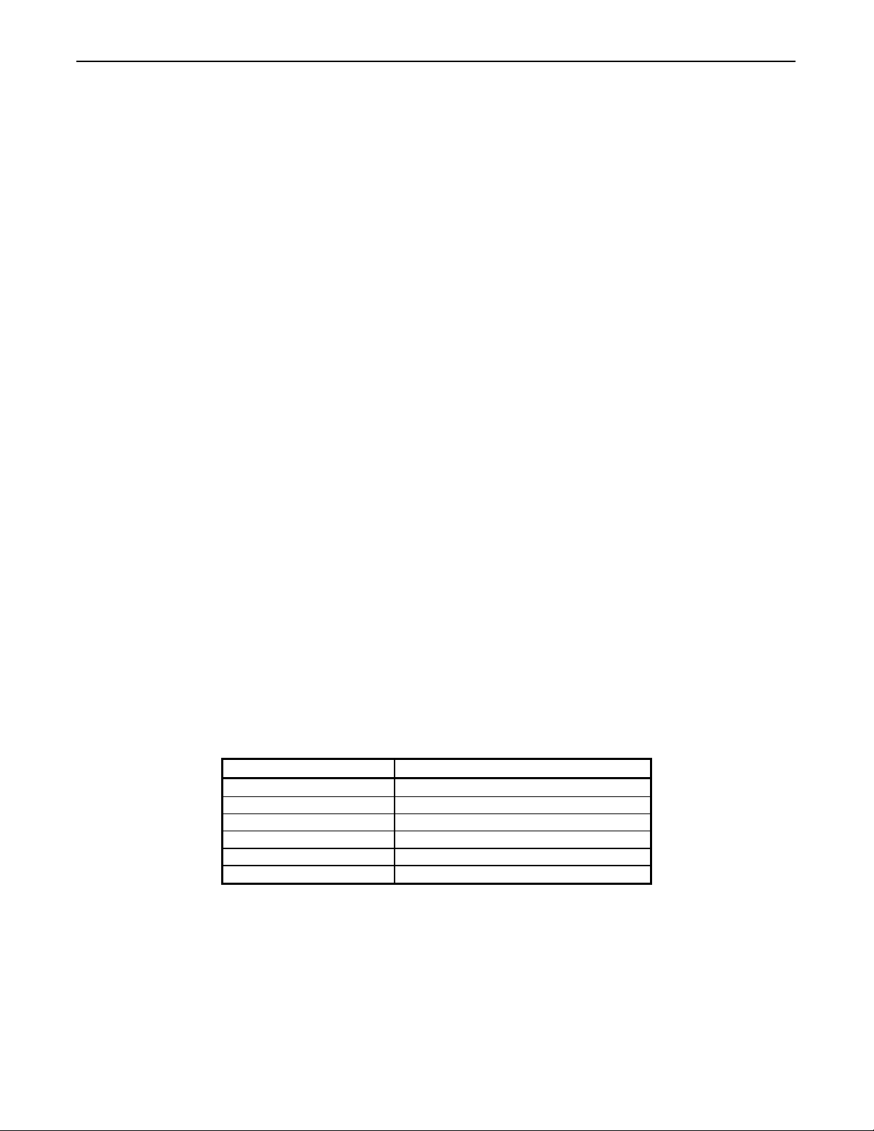
Table 2-3: J7C1 - Bios Setup Configuration Jumper Settings
Function/Mode Jumper Setting Configuration
Normal 1-2 The BIOS uses current configuration
information and passwords for booting
Configure 2-3 After the POST runs, Setup runs
automatically. The maintenance menu is
displayed.
Recovery No jumper The BIOS attempts to recover the BIOS
configuration. A recovery diskette is
required.
Figure 2-1: Intel Desktop Board D815EEA
1
1
1
1
J7C1
Jumper
1
11
1
1
1
1
1
1
1
1
1
1
1
J8C3
Front Panel
J8E1
Seri al Port B J8G3
Di skette Dri ve
J8G2
Pri mary I DE
J8K1
Power
J8G1
Secondary I DE
SDRAM DI MM
(3 Sockets)
J8C2
Aux. Fr. Pane l
power LED`
J8B1
Chassi s Fan
( Fan 1 )
J8C1
Front Panel
USB
J7B1
Chassi s
Intrusion
J7A1
SCSI LED
J6B1
Wake On
LAN Technology
J4A1
PCI Bus
Conn e ct or 5
J4E1
PCI Bus
Conn e ct or 1
J3A1
Communication
and Network
riser (CNR)
J5E1
AGP Uni ve r sa l
Connector
J3H1
Digi tal
Video Out
J3F1
Chassi s Fan
( Fan 2 )
J2F2
CD- ROM
Legacy St yl e
J2F1
ATAPI
CD- ROM
J2G1
Aux. Line In
ATAPI Styl e
J2G2
Tel ephony
ATAPI St yl e
LH 700 Series Workstation Configuration
P/N: 9023736
March 25, 2002 Page
18
2.2. AMI Olympus II ( Series 821 )
This motherboard is produced by American Megatrends Inc® and has the following
features:
• support for Intel® Pentium III® or Intel® Celeron®
• Intel® 815E chipset
• processor heat sink and fan
• 256 KB cache
• memory bus supporting PC133/PC100/PC66 MHz memory
• two 168 pin DIMM memory slots
• AMI Bios
• Ultra DMA IDE disk I/O capability
• On-board 10/100 Ethernet connectivity
• Integrated video controller with 3D graphics and AGP 4X connector
• Cirus Logic CS4299 integrated Audio
• 3 PCI expansion slots
The configuration used in the LH 700 Series Workstation has a 1 GHz Pentium III
processor and 256 MB of 133 MHz RAM
2.2.1. Input and Output Connections
The AMI Olympus II ( Series 821 ) contains 3 PCI bus slots and a Universal AGP slot that
transfer data and control signals between the system card and add-on circuit cards. There
are 3 add-on PCI cards used in the LH 700 Series Workstation, as well as an AGP Video
card installed in the AGP graphics connector.
There are connectors on the system board for connecting to two IDE drives and a floppy
drive. The LH700 Series Workstation uses one hard drive, a CD-R/W drive, and a floppy.
Refer to Figure 2-3: AMI Olympus II – Series 821 for the location of all internal system
board connectors.
Several connectors needed to attach to external devices, such as the keyboard and
mouse, are made available at the back of the computer chassis. Figure 2-2: AMI
Olympus II Back Panel Connectors and Figure 19-2: LH 700 Series Workstation Cable
Connections - AMI show these connectors and their location. Table 2-4: Connector and
Circuit Card Locations on AMI Olymus II describes the various connectors and jumpers
on the board in relation to their use in the LH 700 Series Workstation.
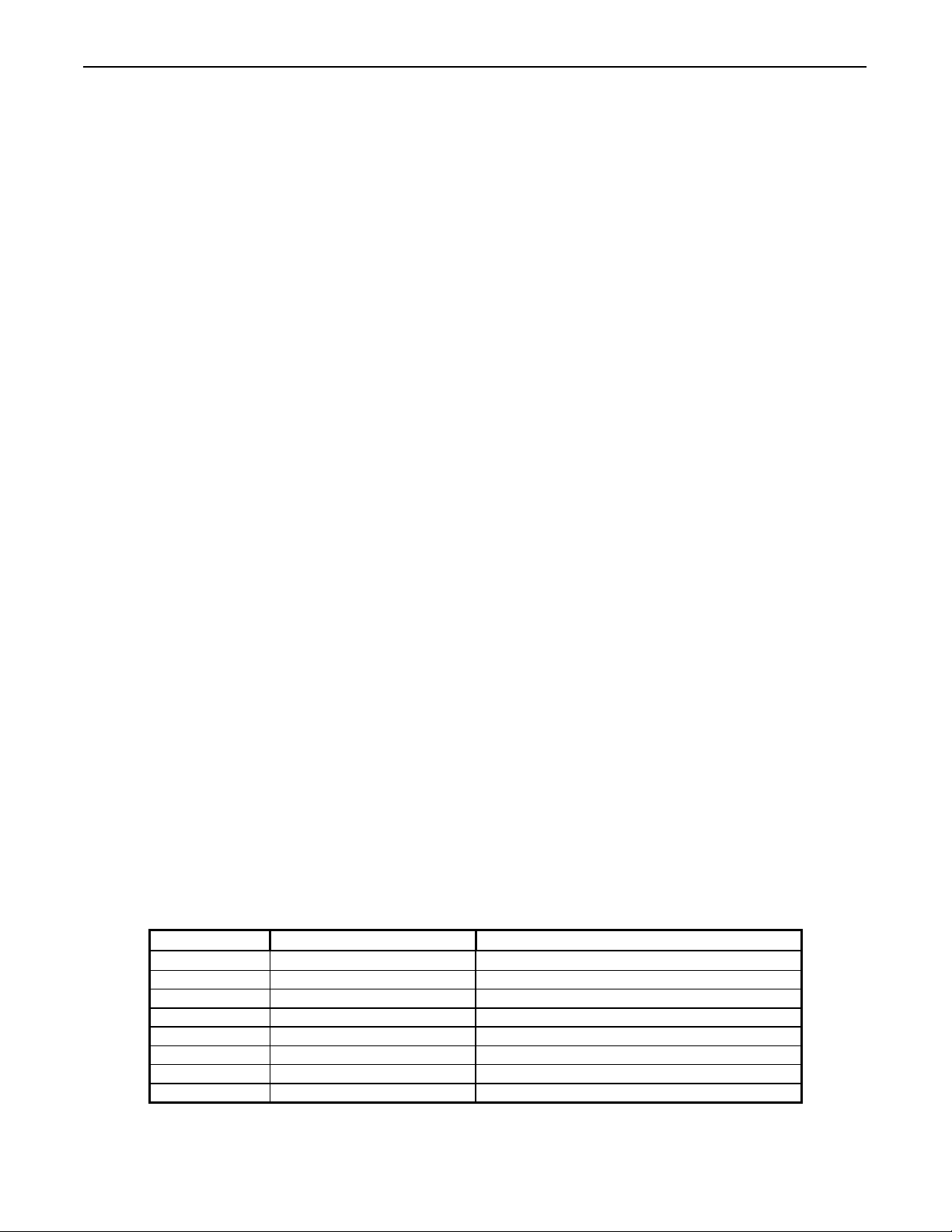
Table 2-4: Connector and Circuit Card Locations on AMI Olymus II
Connector Label or Function Workstation Use or Setting
J5 AGP Video Slot Matrox G550 Video Card
J6 PCI Slot (Slot 1) Adaptec 2930CU SCSI Card
J7 PCI Slot (Slot 2) Equinox SST-4/8P Multi Serial Card
J8 PCI Slot (Slot 3) US Robotics 56K Modem Card
J9 IPMB Not Used
J10 Keyboard Lock Not Used
JP1 CPU Cooling Fan CPU Cooling Fan
JP2 ATX Power Socket Power Supply Connector
LH 700 Series Workstation Configuration
P/N: 9023736
March 25, 2002 Page
19
Connector Label or Function Workstation Use or Setting
JP3 Auxiliary Cooling Fan Rear Panel Cooling fan
JP4 Front Panel See section 2.2.2
JP5 Floppy Floppy Drive
JP6 Primary IDE Hard Drive
JP7 Secondary IDE CD-R/W drive
JP8 CD audio in Audio Connector from CD –R/W drive
JP9 FSB reset (Jumper) Open – not jumpered
JP10 Speaker select (Jumper) Pins 2 and 3 jumpered
JP11 CMOS reset (Jumper) Pins 1 and 2 jumpered
JP12 General purpose I/O Not used
JP13 Internal Speaker Internal speaker on front panel fan mount
JP14 Serial Port Aux serial port located below Power Supply
2.2.2. JP4 Front Panel Connector
JP4 is listed as one connector on the system card, but many small connectors will attach
to it. Table 2-5: JP4 Front Panel Connections lists the connectors used by the LH 700
Series Workstation and the pins that they connect to.
Table 2-5: JP4 Front Panel Connections
Pins Connector
1(+), 3(-) IDE Activity LED – Front panel hard drive
activity LED (red and white wires)
5(-), 7(+) Reset Button – not used
9, 11, 13, 15 LAN Activity LED – not used
2(+), 4(-) System Power LED – Front panel power
indicator (green and white wires)
6(+), 8(-) ATX Power Supply Soft ON/OFF –Front
panel ON/OFF switch (white and black wires)
10(-), 12(+) Suspend LED – not used
14, 16 Not used
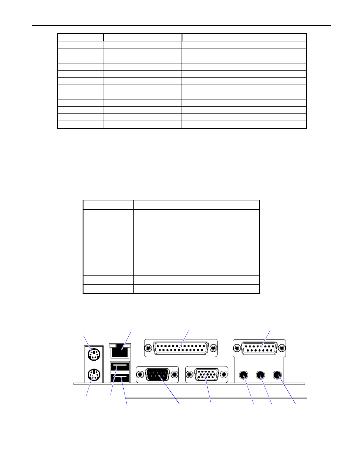
Figure 2-2: AMI Olympus II Back Panel Connectors
Microphone
In
Line
In
Audio Out
(Connect to
Monitor)
Onboard Video
(Not Used)
Serial 1
USB
USB
Keyboard
Mouse
Network
Interface
Parallel Port
(Printer)
Game/MIDI
(Not Used)
LH 700 Series Workstation Configuration
P/N: 9023736
March 25, 2002 Page
20
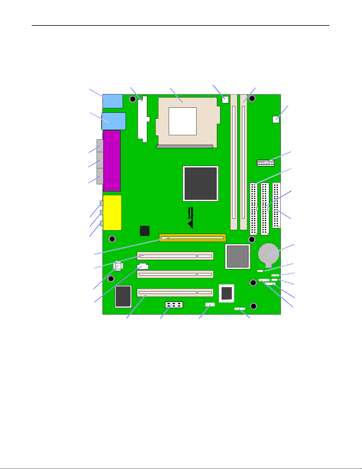
Figure 2-3: AMI Olympus II – Series 821
U3
PPGA Socket 370
JP2
ATX PS
JP1
CPU
Cooling Fan
SDRAM
DIMM
JP3
Auxilliary
Cooling Fan
JP4
JP6
Secondary
IDE
JP5
Floppy
Drive
Battery
JP7
Primary
IDE
JP9
FSB Reset
JP10
Speaker
Select
JP12
General I/O
JP13
Speaker
JP11
CMOS Reset
Keyboard/
Mouse
USB/
LAN
Speaker
Out
Line In
Mic In
Serial
Parallel
(Printer)
Onboard
VGA(Unused)
AGP Video Slot
(Used)
Cirrus Logic
JP8
CD Audio In
J8
PCI Slot
JP14
Serial Port
J9
IPMB
J10
Keyboard Lock
J6
PCI Slot
Table of contents
Popular Desktop manuals by other brands


Sony
Sony PCV-RX550 Specifications

Lenovo
Lenovo ThinkCentre Edge 91z Handboek voor de gebruiker

Lenovo
Lenovo IdeaCentre A540 Series Maintenance manual

Lenovo
Lenovo ThinkCentre M55 Käyttöopas

Sony
Sony VPCL114FX - Vaio L Series All-in-one Touch... Specifications

Panasonic
Panasonic WJ-MX1000AK installation manual

Lenovo
Lenovo 10TV0023IX User guide and hardware maintenance manual

HP
HP Presario SR1200 - Desktop PC Technical specifications

Sony
Sony VGC-JS410F Specifications

HP
HP Compaq Businessdc7600 Service & reference guide

LDI Spaces
LDI Spaces SAFCO MUV 1926 Assembly instructions

J.Burrows
J.Burrows TORO WORKSTATION JBTORO15WS Assembly instructions