Coven 6 EMD MECC Parts list manual

PARTS DIAGRAM FOR THE
ELECTRIC MECHCANICAL COMBI STEAMER
6 EMD MECC
UNIT 1 SWAFFIELD PARK, HYSSOP CLOSE
HAWKS GREEN CANNOCK STAFFS WS11 7FU
TEL: 01543 577778 FAX 01543 504141
Web: www.firstchoice-cs.co.uk

0
Electric mechanical combi steamer
6 EMD MECC
INSTRUCTIONS FOR INSTALLATION, USE AND MAINTENANCE

1
CONTENTS
INSTRUCTIONS FOR THE INSTALLER
Positioning the oven .................................................................................... pag. 2
Installation..................................................................................................... pag. 2
Electrical connection..................................................................................... pag. 2
Water connection.......................................................................................... pag. 3
Connection to water drain............................................................................. pag. 3
Installation diagram....................................................................................... pag. 4
WIRING DIAGRAM
Wiring diagram............................................................................................. pag. 5
Wiring diagram with core temperature probe (optional)............................... pag. 6
Wiring diagram – key................................................................................... pag. 7
TECHNICAL DATA
6EMD MECC oven ....................................................................................... pag. 8
INSTRUCTIONS FOR USER
Controls Fig. 2 .............................................................................................. pag. 9
Maintenance suggestions............................................................................. pag. 10
Instructions for use ....................................................................................... pag. 11
Operating suggestions.................................................................................. pag. 11
Super steam cooking.................................................................................... pag. 12
Mixed convection + steam cookin................................................................. pag. 13
Dry convection cooking................................................................................. pag. 14
Rapid cooling................................................................................................ pag. 15
Core Temperature probe (optional) .............................................................. pag. 16

2
CAUTION
We advise the user to verify that the installation of the equipment be performed in a
proper way; the manufacturer cannot be held responsible for damages resulting from
incorrect installation, poor maintenance or incorrect use.
Before using the oven carefully read the instructions for use. The manufacturer
cannot be held responsible if the requirements indicated in this manual are not observed.
All installation, maintenance or repair operations must be carried out exclusively by
authorized and qualified personnel.
INSTRUCTIONS FOR THE INSTALLER
POSITIONING THE OVEN
Position the equipment on a horizontal surface, well-balanced. The distance between the
back and side walls of the oven must be of at least 50 cm.
INSTALLATION
Remove the plastic film before starting up the oven. Clean all glue residues carefully
without using abrasive substances.
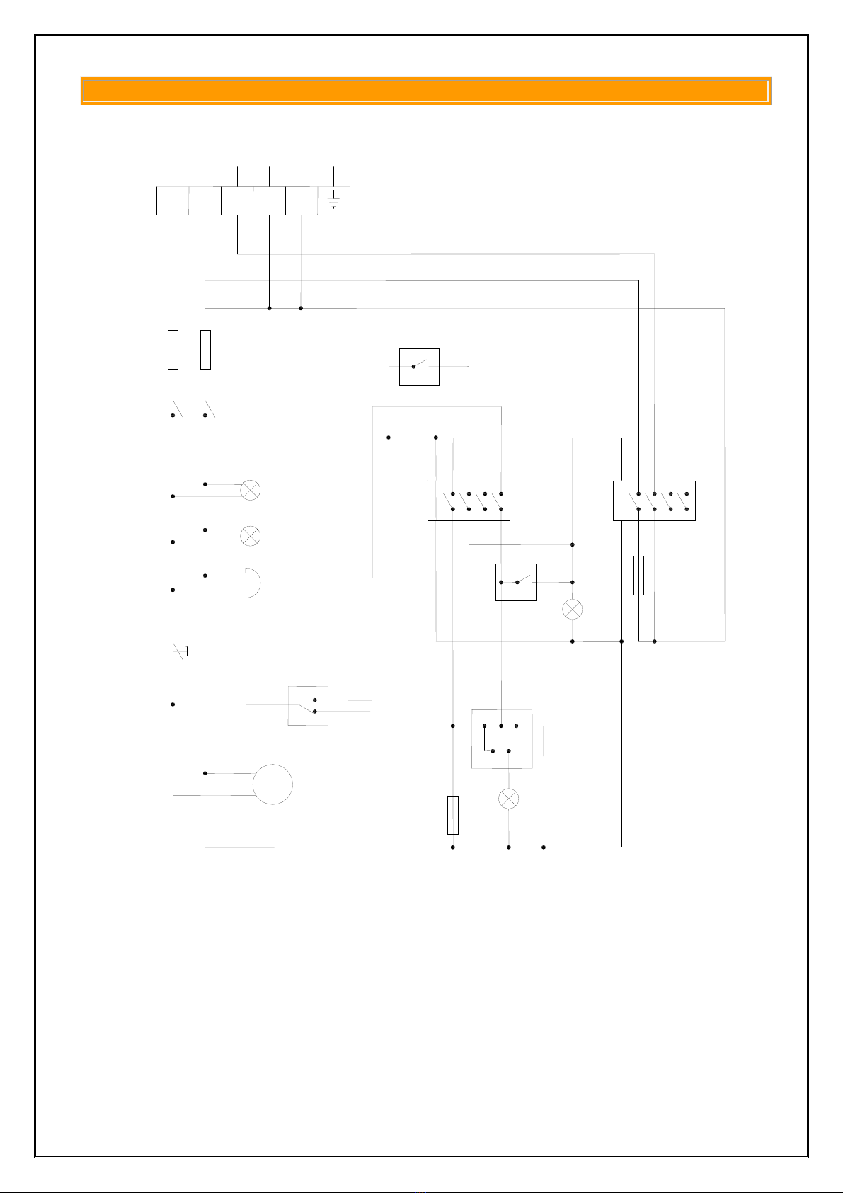
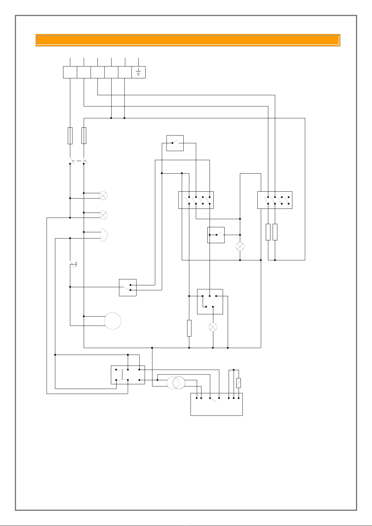
ELECTRICAL CONNECTION
This oven is manufactured to operate at the voltage indicated on the relevant label. To
access the connector board, remove the right side of the unit by removing the fastening
screws.
The flexible wire for connection to the mains must not have characteristics lower than the
ones with rubber insulation model H07RN – F and the section must be the one indicated in
the table “TECHNICAL DATA”.
Connection to the electric line must be made by inserting an automatic switch with
adequate capacity with an opening distance between the contacts of at least 3 mm.
Furthermore, during operation, power supply must not be very different from the value of
the rated voltage ± 10%.
The unit must be connected to a ground outlet. Inside the unit, in the connector board,
there is a terminal with the symbol which the ground wire must be connected to.

3
INSTRUCTIONS FOR THE INSTALLER
The unit must be connected to a ground outlet. Inside the unit, in the connector board,
there is a terminal with the symbol which the ground wire must be connected to.
The equipment must be inserted in an equipotential system, whose effectiveness must be
properly verified according to what is indicated in the regulations in force. Connection must
be made using a screw with this symbol (equipotential) on the rear of the equipment.
The manufacturer cannot be held responsible if this accident-prevention regulation is not
observed.
WATER CONNECTIONS
Connect oven to water line by connecting a pipe to joint ¾” G positioned on the back part
of the oven frameWe suggest using joints with seals for connection, with flexible hose for
high pressures. Verify that at the end of the operations there are no leaks. Use only
material (pipes, joints, etc.) that comply with the standards and that do not leave any rust
build-up.
Caution: A scale inhibitor must always be installed upstream of the equipment. The
hardness of water must be lower than 3°French. If an efficient scale inhibitor is not
installed there will be scale build-up on the equipment and this could affect its proper
operation.
CONNECTION TO WATER DRAIN
Connect system to water drain pipe Ø25mm. (D fig. 1) on the bottom back part of the
oven. Verify that the connected drain pipe has no bents that exceed the height of the joint
itself. Use only materials (pipes, joints, etc.) compliant with the regulations in force and that
in any case do not leave rust build-up.

4
OVEN INSTALLATION DIAGRAM
GG
CH
A
BB
EE
D
L
Legenda
A. Power cable inlet
B. Cooking fumes exhaust
pipe
C. Water inlet (3/4"G male)
D. Water drain (pipe
Ø25mm).
E. Rapid exhaust of steam
G. Boiler cleaning pipe
(only for MX series oven)
H. Drain temperature
reducer inlet (3/4"G
male) – on request

5
WIRING DIAGRAM
Fig. 1a
5
4
F
S
2
13
A
C
EH
1
2
1
A2
A
G
1
A
2
A
R
P
P
L
2
P
ZP
1
2
S
1
S
N
~
M
B
D
TT
1
Q
1
CONVEZ
VAP.SUPER

6
WIRING DIAGRAM 6EMD MECC + CORE TEMPERATURE PROBE (OPTIONAL)
1
2
S1
S
N
~
M
B
D
TT
1
Q
1
CONVEZ.
VAP.SUPER
Y
K
Z
X6
53
42
1
supply
35
5
4
F
S
2
13
A
C
EH
1
2
1
A2
A
G
1
A2
A
R
P
Q
P
L
2
P
2P

7
WIRING DIAGRAM – KEY
A. Timer
B. Line LED
C. Internal light
D. Electronics buzzer
E. Door micro
F. Fuses
G. Super steam thermostat
H. Cooking selector
L. Steam quantity selector
M. Motor fan
N. Steam quantity LED
P. Cooking thermostat
P1. Cooking thermostat LED
Q. Water solenoid
R. Armored resistors
S. Connector board
T. Contactor
T1. Resistor contactor

8
TECHNICAL DATA 6EMD OVEN – TABLE 1
Power KW: 6,7
Power voltage (*): 230 V ~
400 V 3 N ~
Connection cables (H07RN – F)
(H05RN – F/H07RN – F) 3X6 mm² for power 230 V ~
5X2,5 mm² for power 400 V 3 N ~
Cable gland (H07RN – F 3X6)
(H05RN – F 5X2,5)
(H07RN – F 5X2,5)
from 14.5 to 20 mm
from 12.5 to 15.5 mm
from 13.5 to 17 mm
Water inlet pressure: 2 bar min. – 6 bar max.
Water connection:
¾” G
Water drain connection: pipe Ø 25mm.

9
INSTRUCTIONS FOR USER
Fig. 2
1. Combustion fume exhaust
2. Thermometer
3. Thermostat
4. Steam type selector
5. Rapid fume exhaust control
5a Rapid fume exhaust
6. Steam quantity selector
7. Timer
15a
5
c
AUT
SUPER
c
7
6
4
3
2

10
CAUTION
We advise the user to verify that the installation of the unit was performed properly;
the manufacturer cannot be held responsible for damages due to wrong installation,
poor maintenance or incorrect use.
Before starting up the oven, carefully read the instructions for use. The
manufacturer cannot be held responsible for non-compliance with the regulations
laid out in this instructions manual.
The manufacturer cannot be held responsible for any errors or inaccuracy of this
manual due to transcribing or printing errors. Furthermore, the manufacturer
reserves the right to make changes to the equipment deemed necessary or
appropriate, which however do not alter the main features of the equipment..
All the installation, maintenance or repair interventions must be carried out
exclusively by authorized and qualified personnel.
MAINTENANCE SUGGESTIONS
Do not perform any maintenance or cleaning operation without having first
disconnected the oven from the mains.
Periodically clean the oven to avoid hygiene and operation problems. The
equipment must never be washed with direct jets or pressure! Clean steel parts with
water and detergents, do not use acid or aggressive substances or abrasive
detergents. Do not use steel wool sponges, which could leave traces of rust.
For perfect cleaning results follow this procedure:
Spread a diluted degreasing product on the walls of the cooking chamber
Switch on the “super steam cooking” program for 30 minutes
Caution: at the end of the cleaning procedure open the unit very carefully.
The steam contains substances that may damage eyes and hands.
In particular areas, water may leave some sort of rusty deposit on the walls of the
cooking chamber (the stainless steel is not ruined). On request COVEN can supply
a specific cleaning product.

11
INSTRUCTIONS FOR USE
STARTING UP THE OVEN (FIG. 3)
Rotate the timer 1to the right.
Rotate the cooking selector 3 to the left to “convection”.
Set cooking temperature using the thermostat 4.
Control the switching on and off of the resistor when the temperature set using the
thermometer is reached 5 using the LED.
An alternating buzzing sound indicates the end of the set time.
SWITCHING OVEN OFF
At the end of the cooking cycle set temperature back to “0”. Rotate the timer to position
“0”
OPERATING SUGGESTIONS
For steam cooking use stainless steel grids or punched trays. The oven’s capacity
is:
Nr. 6 stainless steel trays 1/1 GN H. 20mm
Nr. 4 stainless steel trays 1/1 GN H. 40mm
Nr. 3 stainless steel trays 1/1 GN H. 65mm
The hot air must be allowed to circulate above and under the product to cook.
Leave free air tracks at least 4 cm. thick above and below the grids.
PRE-HEAT THE OVEN FOR 12 MINUTES (200°C). PRE-HEATING THE OVEN IS
ESSENTIAL TO ASSURE GOOD RESULTS.

12
SUPER STEAM COOKING
To cook verdure fresh vegetables, boiled
meat, thawing frozen food and reduce
cooking times.
a. Switching the oven on
Rotate timer 1 to the right to set a cooking
time between 0÷120 min.
Or to the left (P) continuous function.
b. Select type of cooking
Position knob 3 to the right on " super
steam".
d. It is not necessary to set the
temperature. The oven is programmed
to reach the temperature of 100°C.
FIG. 3
c
A
UT
SUPE
c
R
4
3
2
1
5
6

13
MIXED CONVECTION + STEAM COOKING
To cook roasts, vegetable stews, fruit
pies.
a. Switching the oven on
Rotate timer 1 to the right to set a cooking
time between 0÷120 min.
Or to the left (P) continuous function.
b. Selecting type of cooking
Position knob 3 to the left on "dry
convection"
c. Set temperature
Set desired value by rotating the knob 4.
d. During cooking rotate the knob 2 to
the right.
FIG. 3
c
A
UT
SUPE
c
R
4
3
2
1
5
6

14
To cook lasagna, pizza, grilled meat or
vegetables.
a. Switching the oven on
Rotate timer 1 to the right to set a cooking
time between 0÷120 min.
Or to the left (P) continuous function.
b. Selecting type of cooking
Position knob 3 to the left on "dry
convection"
c. Set cooking temperature.
Set desired value by rotating the knob 4.
d. To eliminate the internal humidity of
certain food enable the control "rapid
steam exhaust" using knob 6
FIG. 3
DRY CONVECTION COOKING
c
A
UT
SUPE
c
R
4
3
2
1
5
6

15
To quickly reduce the temperature inside
the cooking chamber
a. Switching the oven on
Rotate timer 1 to the right to set a cooking
time between 0÷120 min.
Or to the left (P) continuous function.
b. Select rapid cooling
Position the knob 3 up.
FIG. 3
RAPID COOLING
c
A
UT
SUPE
c
R
4
3
2
1
5
6

16
U
P
FIG. 4
Operating instructions
Press knob 1OFF/ON to switch core temperature probe on.
Insert probe into the food.
Press P (knob 2) for a second. Display 5flashes SP1 and a temperature value. Should
you need a different value use knob 3and 4to adjust the temperature, and then press
2. (Should you press for more than a second keys 3and 4, you will increase or
decrease quickly values).
An acoustic signal announces that preset and real temperature inside food are equal.
ATTENTION : All pre-set functions (main temperature, timer, etc.) are stopped by
acoustic signal.
CORE TEMPERATURE PROBE - OPTIONAL
Table of contents