COX CXO300 User manual

INSTALLATION
GUIDE
–––
CXO300 – designed for
purpose
coxmarine.com


TABLE OF CONTENTS
1.0
2.0
3.0
4.0
5.0
6.0
7.0
8.0
9.0
10.0
11.0
12.0
13.0
14.0
INTRODUCTION
INSPECTION OF OUTBOARD
REMOVAL OF OUTBOARD ENGINE FROM THE CRATE
MOUNTING THE OUTBOARD ONTO THE TRANSOM
RIGGING INSTALLATION
STEERING
RIGGING TUBE INSTALLATION
FUEL SYSTEM INSTALLATION
POWER SUPPLY
WIRING HARNESS INSTALLATION
HELM CONTROL INSTALLATION
OUTBOARD OIL FILL
APPLYING GREASE TO THE PTT
INSTALLING THE TOP COWL
4
5
6
10
16
27
31
34
38
41
48
55
57
59

4CXO300 INSTALLATION MANUAL
1.0 INTRODUCTION
1.0 INTRODUCTION
1.1 INTRODUCTION
The purpose of this document is to define the procedures or steps that are required to be done in order
to do a safe and correct installation of a CXO300 outboard engine(s).
The different systems of the outboard(s) are designed to work together continuously to provide a safe
and reliable boating experience.
Any modifications to the outboard(s) or deviation to installing the units to as described in the procedures
of this document, is likely to affect safety, legality and longevity and should be expressly avoided.
1.2 EMISSIONS-RELATED INSTALLATION INSTRUCTION (USA)
In order to ensure emissions compliance of the installed outboard(s), it is essential that the processes
and requirements detailed in ‘Section 8.0.0’ of the document are adhered to.
Failing to follow these instructions when installing a certified engine in a vessel violates federal law
(40 CFR 1068.105(b)), subject to fines or other penalties as described in the Clean Air Act.
This product is EPA Tier 3 compliant and can be used on US flagged vessels. To support US registered
vessels to operate internationally, this marine engine is also certified to IMO Annex VI Tier II
standards, and may therefore be limited to use on new and/or non-exempt vessels that meet one of
the following criteria:
1 Recreational vessels < 24 meters in length under Annex VI Regulation 13.5.2.1
2 Vessels with a Tier III exemption for combined nameplate of <750kW due to ships design or
construction limitations under Annex VI Regulation 13.5.2.2
3 Recreational vessels of >24m with gross tons < 500, and a keel laid date < January 1, 2021, per
Annex VI Regulation 13.5.2.3
If you install the engine in a way that makes the engine’s emission control information label hard to
read during normal engine maintenance, you must place a duplicate label on the vessel, as described
in 40 CFR 1068.105.
5
CXO300 INSTALLATION MANUAL 2.0 INSPECTION OF OUTBOARD
INSPECTION OF OUTBOARD 2.0
2.1 INSPECTION OF OUTBOARD AFTER DELIVERY AT INSTALLATION LOCATION
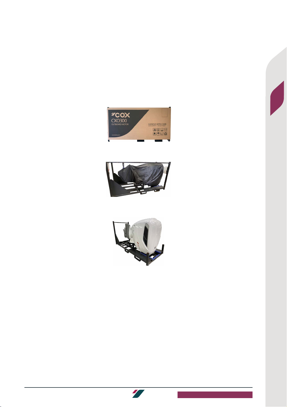
2.1.0 Before you remove the outboard from the packaging, make sure that you inspect the packaging
for damage(s) during shipping and storage.
2.2.0 Make sure that you do a check for damage on the outer packaging.
2.3.0 Remove the packaging straps and outer packaging.
2.4.0 Make sure that the outboard is mounted safely and the Power Tilt and Trim (PTT) lock is on.
2.5.0 Make sure that the outboard specification (color, leg length and gear ratio) is correct.
2.6.0 Make sure that you do a check for damage on the outboard cover.
2.7.0 Remove the outboard cover and make sure that you do a check for damage on the outboard
cover again.
2.8.0 Make sure you speak to your distributor or local Cox service provider for aid if:
2.8.1 Damages can be seen on the outboard, outboard cover and packaging.
2.8.2 Outboard specification is not correct.
2.8.3 Outboard is not mounted safely, and the PTT lock is not on.

6CXO300 INSTALLATION MANUAL
3.0 REMOVAL OF OUTBOARD ENGINE
3.0 REMOVAL OF OUTBOARD ENGINE FROM THE CRATE
3.1.0 Attach the applicable straps or chains to the correct points on the metal transportation crate
(Figure 3.1a)
Figure 3.1a. Points for attaching straps and steps for lifting the metal transportation crate with
outboard to a vertical position.
3.2.0 Using a gantry crane (or A-frame gantry crane) lift the crate to a vertical position.
3.3.0 Remove the straps or chains from the crate.
3.4.0 Remove the propeller shaft steady bar.
3.5.0 Remove the two long vertical rails.
3.6.0 Remove the top frame from the crate.
3.7 REMOVAL OF OUTBOARD TOP COWL
3.7.1 Open the three latches that hold the top cowl to the outboard.
3.7.2 Remove the outboard top cowl and stow it safely; if working on multiple outboard, ensure cowls
are labeled.
3.7.3 Close the three latches that hold the top cowl onto the outboard.
3.8.0 Remove the lifting eye cover from the top cover.
3.8.1 Use the applicable torx drive to remove the torx screws (2).
WARNING
If you are working on multiple outboards, make sure each cowl is marked for install to its initial outboard.
CAUTION
If you use an incorrect torx driver, it will damage the torx screw head.

7
CXO300 INSTALLATION MANUAL 3.0 REMOVAL OF OUTBOARD ENGINE
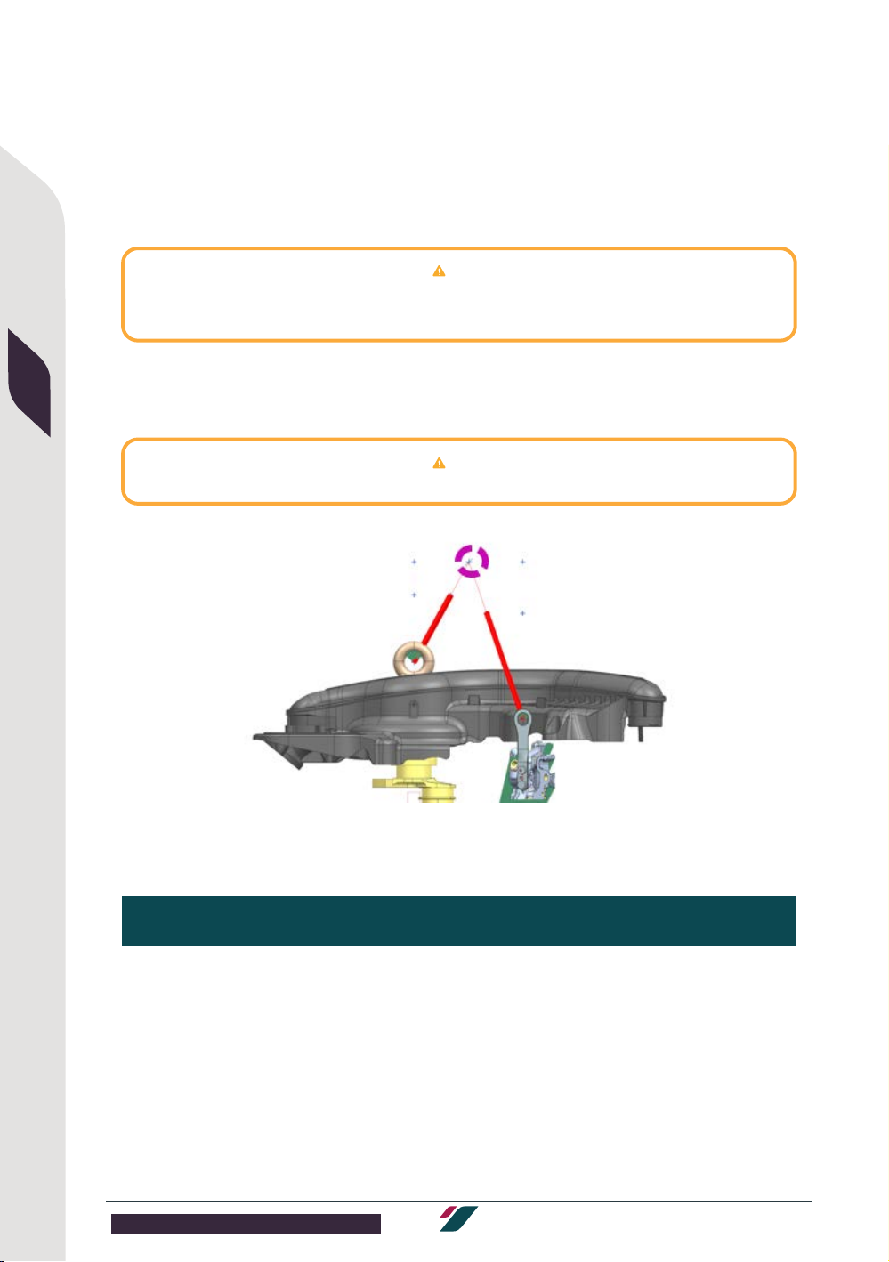
3.9.0 Remove the crank pulley cover.
3.9.2 Use 14mm hex driver or Allen key to remove the crank pully cover.
3.10.0 Install the centre lifting eye and sleeve (Kit No. 909427) . Hand tight only.
3.10.1 When the centre lifting eye is tight, if the eye orientation is not within 45° of the centre line of the
outboard, bar over the engine until it is in the correct orientation as shown.
3.11.0 Install the right hand lifting eye (909441) to the starboard/right cylinder head (Figure3.11) and
torque the two fasteners (029355) to 23Nm.
Figure 3.11 Lift hooks and lifting eyes positions on the outboard.
8CXO300 INSTALLATION MANUAL
3.0 REMOVAL OF OUTBOARD ENGINE
3.0 REMOVAL OF OUTBOARD ENGINE FROM THE CRATE
3.12.0 Install the left hand lifting eye (909440) to the port/left cylinder head (Figure 3.11) and torque
the two fasteners (029355) to 23Nm.
3.13.0 Attach the three point lifting frame to the lifting eyes or attach three straps of length detailed
in the table below. Make sure that you apply equal tension to all the straps for vertical lifting of
the outboard.
Minimum strop lengths for lifting the outboard are detailed in the table below. Using a longer strop length
with result in a greater angle than 25°.
3.14.0 Remove the bolts that hold the PTT to the crate.
3.15.0 Move the outboard to a safe position.
Minimum strop length required at 25° to the vertical (mm)
Centre Lifting Eye 420
Left-hand Lifting Eye - Port 590
Right-hand Lifting Eye - Starboard 590
NOTE
Unequal loading of straps may result in damage to outboard during lifting.
NOTE
Working load limit (WLL) for left-hand lifting eye (909440) and right-hand lifting eye (909441):
Vertical outboard lift WLL = 500kg 25° vertical outboard lift WWL = 96kg

9
CXO300 INSTALLATION MANUAL 3.0 REMOVAL OF OUTBOARD ENGINE
3.16.0 Assemble the crate again.
3.17.0 Keep or send the crate back to Cox.
CAUTION
Do not reuse any fasteners from the shipping crate for the installation of the outboard to a vessel -
the fasteners are for shipping purposes only. Use only components from the supplier rigging kits for
installation to vessel.

10 CXO300 INSTALLATION MANUAL
4.0 MOUNTING THE OUTBOARD
4.0 MOUNTING THE OUTBOARD ONTO THE TRANSOM
4.1.0 Before you drill the mounting holes, make sure that:
4.1.1 The outboard is appropriate for the vessel.
4.1.2 The mounting hole positions are identified correctly.
4.2.0 Make sure that the vessel is rated for the power output of the outboard(s).
4.3.0 Make sure that the vessel transom is sufficiently strong to mount the outboard.
4.4.0 Make sure that there is sufficient clearance to steer and trim the outboard engine(s).
4.5.0 Make sure that you use an applicable method to identify the correct center line of the
outboard. For example:
4.5.1 Identify the center point between two chines and draw a line down the centric-V of the vessel,
as shown on Figure 4.5.
4.5.2 If you are not sure about the center line position, speak to the boat builder for aid.
4.6.0 Make sure that you use the center line mark as the datum (the fixed starting point to measure
the distance from the center line) for installing multiple outboards.
4.6.1 Use the table in figure 4.6 to determine the distance between centers and any applicable
steering system limits.
D
D
C
C
B
B
A
A
Figure 4.5. Vessel
with center line from
the transom to the
center-V.
Figure 4.4 Vessel displaying center lines on the vessel and on the outboards
A - 30°B - 337mm C - 565.6mm D - see figure4.6

11
CXO300 INSTALLATION MANUAL 4.0 MOUNTING THE OUTBOARD
4.6 Outboard steering angle relationship
4.7.0 Make sure the mounting position marks are at the correct height for the outboard(s).
CXO300 Outboard Install Guide (based on current Cox steering systems)
Between centres
724 [28.5] 762 [30] 784 [30.9]
Single
Install
Twin Install Triple
Install
Quad
Install
Twin Install Triple
Install
Quad
Install
Twin
Install
Triple
Install
Quad
Install
Parallel Asymmetric Parallel Asymmetric
Maximum
Envelope
(mm [in])
1131
[44.5276}
1652
[65.0394]
1885
[73.0315]
2376
[93.5433]
3100
[122.0472]
1836
[72.5276]
1893
[74 .5276 ]
2598
[102. 28 35]
3360
[132.2835]
1915
[75.3937]
2699
[106. 2598]
3483
[137.126]
Maximum steering angle (°)
Port turn
Angle A 30 17 30 17 17 26 30 26 26 30 30 30
Angle B 17 20 17 17 26 27 26 26 30 30 30
Angle C 17 17 26 26 30 30
Angle D 17 26 30
Starboard turn
Angle E 30 17 20 17 17 26 27 26 26 30 30 30
Angle F 17 30 17 17 26 30 26 26 30 30 30
Angle G 17 17 26 26 30 30
Angle H 17 26 30

12 CXO300 INSTALLATION MANUAL
4.0 MOUNTING THE OUTBOARD
4.0 MOUNTING THE OUTBOARD ONTO THE TRANSOM
4.7.1 Make sure the positioning of the anti-ventilation plate is in line with the bottom
of the hull directly in front of it.
4.7.2 Make sure that the anti-ventilation plate and the water line is at the correct height. Cox
offer 3 outboard leg lengths (25”, 30” and 35”) to make sure that the outboard operates
correctly with the vessel.
4.7.3 Make sure that you use the dimensions in Figure 4.8 to select the correct outboard leg length
for the vessel.
Figure 4.7 Information about the three leg lengths of the outboard engine. Units mm (in)
25”
A 609 (24)
B 1997 (78.6)
C 141 (5.6)
D 1241 (47.8)
E R1286 (50.7)
F 918 (36.1)
G 853 (33.58)
30”
A 732 (29)
B 2124 (83.6)
C 268 (10.5)
D 1341 (52.8)
E R1413 (55.6)
F 1045 (41.1)
G 853 (33.58)
35”
A 863 (34)
B 2251 (88.6)
C 395 (15.6)
D 1468 (57.8)
E R1540 (60.7)
F 1172 (46.1)
G 853 (33.58)

13
CXO300 INSTALLATION MANUAL 4.0 MOUNTING THE OUTBOARD
4.8.0 Make sure that the water line of the vessel is between the lines which are shown on the
outboard in Figure 4.9.
Figure 4.8. Minimum and maximum water lines on the outboard engine.
4.9.0 Make sure that you read the information of the different leg lengths on multiple outboard
installs in Figure 4.9. It will help you put the PTT mountings in the correct position for
the correct steering geometry.
Figure 4.9 Different leg lengths on multiple outboard installations
4.10.0 When the positions for the center line(s) and height(s) are found.
4.10.1 Make marks at the positions of the six holes for the outboard(s).
4.10.2 Make sure that you use the supplied template (Servicing Kit No: 037023, figure 4.10) to get
the correct positions of the mounting holes.
4.10.3 Make sure that you use two bolts on each side for the six top holes.
4.10.4 Make sure that you use one bolt on each side for the bottom hole.
Max water line - make
sure that the exhaust
idle vent is out of the
water
Min water line - make
sure that the water
pump is covered for
correct operation

14 CXO300 INSTALLATION MANUAL
4.0 MOUNTING THE OUTBOARD
4.0 MOUNTING THE OUTBOARD ONTO THE TRANSOM
4 .11.0 Make sure that you use a 6 mm pilot drill to make initial holes in the transom. Make sure that
the drill is always at 90 degrees to the transom when drilling the holes.
4.12.0 Make sure that you use a clearance drill to finish the holes for the 12 mm bolts (M12).
4.13.0 Make sure that you use the correct specification bolts, nuts and washers (M12 x 1.75mm
Stainless Steel grade A4-80) to attach the outboard to the transom.
4.13.1 Make sure that the length of the bolts are long enough to go through the PTT, transom , the
lock nut and all washers.
4.13.2 Make sure two full threads of the bolts are showing through the nyloc nuts.
4.14.0 Make sure that you apply marine sealant (Sikaflex 291i or equivalent) to the areas around the
mounting holes on the PTT and to transom face.
4.15.0 Make sure that you use a gantry crane (A-frame) to move the outboard into position and mount
to transom.
4.16.0 Make sure that you apply marine sealant (sikaflex 291i or equivalent) to the bolts. Torque the
fasteners to 80 Nm.
BB
A
A
CC
D
E
H
F
G
Figure 4.10
Engineering
drawing showing
the PTT-Transom
layout - mm (in).
A 13 (0.51)
B 163.5 (6.44)
C 125.4 (4.94)
D 95.2 (3.75)
E 318.5 (12.54)
F 92.5 (3.64)
G 115.3 (4.54)
H 18.5 (0.73)

15
CXO300 INSTALLATION MANUAL 4.0 MOUNTING THE OUTBOARD
4.17.0 Remove the lifting straps or chains from the outboard and move the crane to a safe area.
4.18.0 If you are doing a multiple installation, repeat steps 4.15.0 through 4.18.0 for each outboard to
be installed.
4.19.0 Remove the lifting eyes (3) and install the crank pulley cover. Torque the crank pulley cover to
9-11 Nm.
4.20.0 Place the lifting eye cover on the top cover. Torque the torx screws (2) to 3 Nm.

16 CXO300 INSTALLATION MANUAL
5.0 RIGGING INSTALLATION
5.0 RIGGING INSTALLATION
5.1. RIGGING KITS
5.1.1 Make sure that you use the applicable rigging kits. There are different rigging kits for different
vessel or outboard configuration.
5.1.2 Make sure that the contents of the rigging kits are correct before you start the rigging
installation.
Single Install Twin Install Triple Install Quad Install Quintuple Install Sextuple Install
Components Part Number Without Steering
SK-000103 With Steering SK-000097 Without Steering
SK-000080 With Steering SK-000081 Without Steering
SK-000082 With Steering SK-000078 Without Steering
SK-000079 With Steering SK-000083 Without Steering
SK-000084
Without Steering
SK-000085
Seastar Control Head, Single Lever 034392 ●/1 ●/1 -- -- -- -- -- -- -- --
Seastar Control Head, Dual Lever 034391 -- -- ●/1 ●/1 ●/1 ●/1 ●/1 ●/1 ●/1 ●/1
Coastkey, Start Panel 033979 ●/1 ●/1 ●/1 ●/1 ●/1 ●/1 ●/1 ●/1 ●/1 ●/1
Coastkey, 2 button fob 033980 ●/1 ●/1 ●/1 ●/1 ●/1 ●/1 ●/1 ●/1 ●/1 ●/1
Coastkey, CECU Eng 1 033981 ●/1 ●/1 -- -- -- -- -- -- -- --
Coastkey, CECU Eng 1-2 033982 -- -- ●/1 ●/1 ●/1 ●/1 ●/1 ●/1 ●/1 ●/1
Coastkey, CECU Eng 3 033983 -- -- -- -- ●/1 ●/1 -- -- -- --
Coastkey, CECU Eng 3-4 033984 -- -- -- -- -- -- ●/1 ●/1 ●/1 ●/1
Coastkey, CECU Eng 5-6 033985 -- -- -- -- -- -- -- -- ●/1 ●/1
Fuel Lift Pump Unit 037236 ●/1 ●/1 ●/2 ●/2 ●/3 ●/3 ●/4 ●/4 ●/5 ●/6
Outboard to Vessel CAN Harness 033870 ●/1 ●/1 ●/2 ●/2 ●/3 ●/3 ●/4 ●/4 ●/5 ●/6
Outboard to Vessel Controls Harness 033871 ●/1 ●/1 ●/2 ●/2 ●/3 ●/3 ●/4 ●/4 ●/5 ●/6
CAN T Piece 034393 ●/4 ●/6 ●/6 ●/8 ●/8 ●/10 ●/10 ●/12 ●/12 ●/14
CAN Terminating Resistor Female 034394 ●/2 ●/2 ●/3 ●/3 ●/4 ●/4 ●/5 ●/5 ●/6 ●/7
CAN Terminating Resistor Male 034395 ●/1 ●/1 ●/1 ●/1 ●/1 ●/1 ●/1 ●/1 ●/1 ●/1
Trim Panel, Twin Install 033939 -- -- ●/1 ●/1 -- -- ●/1 ●/1 -- --
Trim Panel, Triple Install 0 33 749 -- -- -- -- ●/1 ●/1 -- -- ●/1 ●/1
CAN connector cover Female 034986 ●/1 ●/1 ●/2 ●/2 ●/3 ●/3 ●/4 ●/4 ●/5 ●/6
Flush Adaptor 034363 ●/1 ●/1 ●/2 ●/2 ●/3 ●/3 ●/4 ●/4 ●/5 ●/6
ECU power harness 036484 ●/1 ●/1 ●/2 ●/2 ●/3 ●/3 ●/4 ●/4 ●/5 ●/6
Outboard to vessel fuel lines 031164 ●/1 ●/1 ●/2 ●/2 ●/3 ●/3 ●/4 ●/4 ●/5 ●/6
Outboard busbar nut 025599 ●/2 ●/2 ●/4 ●/4 ●/6 ●/6 ●/8 ●/8 ●/10 ●/12
Seastar Optimus EPS Core Pack, Single Install 027834 -- ●/1 -- -- -- -- -- -- -- --
Seastar Optimus EPS Core Pack, Twin Install 027166 -- -- -- ●/1 -- ●/1 -- ●/1 -- --
Seastar Steering Smart Cylinder, Tournament Series, Standard 027168 -- ●/1 -- ●/2 -- ●/1 -- -- -- --
Seastar Steering Smart Cylinder, Tournament Series, with Starboard-side Tie Bar Bracket 034385 -- -- -- -- -- ●/1 -- ●/1 -- --
Seastar Tie Bar, Tournament Series, Large 034386 -- -- -- -- -- ●/1 -- ●/2 -- --
Seastar Tie Bar Hardware Kit 034387 -- -- -- -- -- ●/1 -- ●/2 -- --
Seastar Optimus EPS Front-Mount Helm Unit 027169 -- ●/1 -- ●/1 -- ●/1 -- ●/1 -- --
Seastar Optimus EPS CAN1 Harness, 30ft 027170 -- ●/1 -- ●/1 -- ●/1 -- ●/1 -- --
Seastar Pro Hydraulic Steering Hose Kit, 10ft 027172 -- ●/1 -- ●/2 -- ●/2 -- ●/2 -- --
Seastar Optimus EPS CAN3 Harness, 3ft 027173 -- ●/1 -- ●/1 -- ●/1 -- ●/1 -- --
KIT, Steering Cylinder Spacer SK-000100 -- ●/1 ●/2 ●/2 ●/2 ●/2 ●/2 ●/2 ●/2 ●/2
Extension Harness Part Number
CAN Vessel Harness 1m 033872 ○/1 ○/1 ○/1 ○/1 ○/1 ○/1
CAN Vessel Harness 4m 033873 ○/1 ○/1 ○/1 ○/1 ○/1 ○/1
CAN Vessel Harness 6m 03 3874 ○/1 ○/1 ○/1 ○/1 ○/1 ○/1
CAN Vessel Harness 8m 033875 ○/1 ○/1 ○/1 ○/1 ○/1 ○/1
Vessel Helm Control Harness 4m 033876 ○/1 ○/2 ○/3 ○/4 ○/5 ○/6
Vessel Helm Control Harness 6m 033877 ○/1 ○/2 ○/3 ○/4 ○/5 ○/6
Vessel Helm Control Harness 8m 033878 ○/1 ○/2 ○/3 ○/4 ○/5 ○/6
Helm Screen Kits Part Number
Murphy PV450 4” Screen Kit SK-000134 ○/1 ○/1 ○/1 ○/1 ○/1 ○/1
Murphy PV780B 7” Screen Kit SK-000135 ○/1 ○/1 ○/1 ○/1 ○/1 ○/1
Murphy PV1200 12” Screen Kit SK-000136 ○/1 ○/1 ○/1 ○/1 ○/1 ○/1
Helm Screen Kits Part Number
Victron Energy Orion-Tr 12/12-30A (360W) Isolated DC-DC Converter 038206 ●/1 ●/1 ●/1 ●/1 ●/1 ●/1 ●/1 ●/1 ●/1 ●/1
Voltage Sensing Battery Combiner (Not Supplied by Cox) - ●/1 ●/1 ●/1 ●/1 ●/1 ●/1 ●/1 ●/1 ●/1 ●/1
KEY: STANDARD/QUANTITY
●/1
INSTALLATION-SPECIFIC/QUANTITY
○/1
MAX EXTENSIONS (m)

17
CXO300 INSTALLATION MANUAL 5.0 RIGGING INSTALLATION
5.1.3 There are three lengths (4m, 6m and 8m) of vessel CAN and Helm controls harnesses
that are provided in the rigging kit. If a vessel harness which is longer than 8m is necessary,
make sure you speak to your Cox service provider about it. The rigging kits are as follows:
Figure 5.1 Rigging Kit Contents
Single Install Twin Install Triple Install Quad Install Quintuple Install Sextuple Install
Components Part Number Without Steering
SK-000103 With Steering SK-000097 Without Steering
SK-000080 With Steering SK-000081 Without Steering
SK-000082 With Steering SK-000078 Without Steering
SK-000079 With Steering SK-000083 Without Steering
SK-000084
Without Steering
SK-000085
Seastar Control Head, Single Lever 034392 ●/1 ●/1 -- -- -- -- -- -- -- --
Seastar Control Head, Dual Lever 034391 -- -- ●/1 ●/1 ●/1 ●/1 ●/1 ●/1 ●/1 ●/1
Coastkey, Start Panel 033979 ●/1 ●/1 ●/1 ●/1 ●/1 ●/1 ●/1 ●/1 ●/1 ●/1
Coastkey, 2 button fob 033980 ●/1 ●/1 ●/1 ●/1 ●/1 ●/1 ●/1 ●/1 ●/1 ●/1
Coastkey, CECU Eng 1 033981 ●/1 ●/1 -- -- -- -- -- -- -- --
Coastkey, CECU Eng 1-2 033982 -- -- ●/1 ●/1 ●/1 ●/1 ●/1 ●/1 ●/1 ●/1
Coastkey, CECU Eng 3 033983 -- -- -- -- ●/1 ●/1 -- -- -- --
Coastkey, CECU Eng 3-4 033984 -- -- -- -- -- -- ●/1 ●/1 ●/1 ●/1
Coastkey, CECU Eng 5-6 033985 -- -- -- -- -- -- -- -- ●/1 ●/1
Fuel Lift Pump Unit 037236 ●/1 ●/1 ●/2 ●/2 ●/3 ●/3 ●/4 ●/4 ●/5 ●/6
Outboard to Vessel CAN Harness 033870 ●/1 ●/1 ●/2 ●/2 ●/3 ●/3 ●/4 ●/4 ●/5 ●/6
Outboard to Vessel Controls Harness 033871 ●/1 ●/1 ●/2 ●/2 ●/3 ●/3 ●/4 ●/4 ●/5 ●/6
CAN T Piece 034393 ●/4 ●/6 ●/6 ●/8 ●/8 ●/10 ●/10 ●/12 ●/12 ●/14
CAN Terminating Resistor Female 034394 ●/2 ●/2 ●/3 ●/3 ●/4 ●/4 ●/5 ●/5 ●/6 ●/7
CAN Terminating Resistor Male 034395 ●/1 ●/1 ●/1 ●/1 ●/1 ●/1 ●/1 ●/1 ●/1 ●/1
Trim Panel, Twin Install 033939 -- -- ●/1 ●/1 -- -- ●/1 ●/1 -- --
Trim Panel, Triple Install 0 33 749 -- -- -- -- ●/1 ●/1 -- -- ●/1 ●/1
CAN connector cover Female 034986 ●/1 ●/1 ●/2 ●/2 ●/3 ●/3 ●/4 ●/4 ●/5 ●/6
Flush Adaptor 034363 ●/1 ●/1 ●/2 ●/2 ●/3 ●/3 ●/4 ●/4 ●/5 ●/6
ECU power harness 036484 ●/1 ●/1 ●/2 ●/2 ●/3 ●/3 ●/4 ●/4 ●/5 ●/6
Outboard to vessel fuel lines 031164 ●/1 ●/1 ●/2 ●/2 ●/3 ●/3 ●/4 ●/4 ●/5 ●/6
Outboard busbar nut 025599 ●/2 ●/2 ●/4 ●/4 ●/6 ●/6 ●/8 ●/8 ●/10 ●/12
Seastar Optimus EPS Core Pack, Single Install 027834 -- ●/1 -- -- -- -- -- -- -- --
Seastar Optimus EPS Core Pack, Twin Install 027166 -- -- -- ●/1 -- ●/1 -- ●/1 -- --
Seastar Steering Smart Cylinder, Tournament Series, Standard 027168 -- ●/1 -- ●/2 -- ●/1 -- -- -- --
Seastar Steering Smart Cylinder, Tournament Series, with Starboard-side Tie Bar Bracket 034385 -- -- -- -- -- ●/1 -- ●/1 -- --
Seastar Tie Bar, Tournament Series, Large 034386 -- -- -- -- -- ●/1 -- ●/2 -- --
Seastar Tie Bar Hardware Kit 034387 -- -- -- -- -- ●/1 -- ●/2 -- --
Seastar Optimus EPS Front-Mount Helm Unit 027169 -- ●/1 -- ●/1 -- ●/1 -- ●/1 -- --
Seastar Optimus EPS CAN1 Harness, 30ft 027170 -- ●/1 -- ●/1 -- ●/1 -- ●/1 -- --
Seastar Pro Hydraulic Steering Hose Kit, 10ft 027172 -- ●/1 -- ●/2 -- ●/2 -- ●/2 -- --
Seastar Optimus EPS CAN3 Harness, 3ft 027173 -- ●/1 -- ●/1 -- ●/1 -- ●/1 -- --
KIT, Steering Cylinder Spacer SK-000100 -- ●/1 ●/2 ●/2 ●/2 ●/2 ●/2 ●/2 ●/2 ●/2
Extension Harness Part Number
CAN Vessel Harness 1m 033872 ○/1 ○/1 ○/1 ○/1 ○/1 ○/1
CAN Vessel Harness 4m 033873 ○/1 ○/1 ○/1 ○/1 ○/1 ○/1
CAN Vessel Harness 6m 03 3874 ○/1 ○/1 ○/1 ○/1 ○/1 ○/1
CAN Vessel Harness 8m 033875 ○/1 ○/1 ○/1 ○/1 ○/1 ○/1
Vessel Helm Control Harness 4m 033876 ○/1 ○/2 ○/3 ○/4 ○/5 ○/6
Vessel Helm Control Harness 6m 033877 ○/1 ○/2 ○/3 ○/4 ○/5 ○/6
Vessel Helm Control Harness 8m 033878 ○/1 ○/2 ○/3 ○/4 ○/5 ○/6
Helm Screen Kits Part Number
Murphy PV450 4” Screen Kit SK-000134 ○/1 ○/1 ○/1 ○/1 ○/1 ○/1
Murphy PV780B 7” Screen Kit SK-000135 ○/1 ○/1 ○/1 ○/1 ○/1 ○/1
Murphy PV1200 12” Screen Kit SK-000136 ○/1 ○/1 ○/1 ○/1 ○/1 ○/1
Helm Screen Kits Part Number
Victron Energy Orion-Tr 12/12-30A (360W) Isolated DC-DC Converter 038206 ●/1 ●/1 ●/1 ●/1 ●/1 ●/1 ●/1 ●/1 ●/1 ●/1
Voltage Sensing Battery Combiner (Not Supplied by Cox) - ●/1 ●/1 ●/1 ●/1 ●/1 ●/1 ●/1 ●/1 ●/1 ●/1
KEY: STANDARD/QUANTITY
●/1
INSTALLATION-SPECIFIC/QUANTITY
○/1
MAX EXTENSIONS (m)

18 CXO300 INSTALLATION MANUAL
5.0 RIGGING INSTALLATION
5.0 RIGGING INSTALLATION
*
i
ii
B
Rigging Component Part Number
Vessel Helm Control Harness 8m (One
per outboard) 033878
Key
CAN Harness
Helm Controls Harness
12v switched ignition feed
CoastKey Connection
PTT Connection
Fuel Level Sensor
12v Positive
12v Negative
Dometic CAN1
Dometic CAN3
Breaker
Battery Switch
Service Tool Connection
CAN T-Piece
CAN Terminating Resistor
Second Station Extension #
Engine Battery
CoastKey Start Panel
CoastKey ECU
Lift Pump
Fuel Pump
Water In Fuel Sensor
4 inch Screen
7 inch Screen
12 inch Screen
Trim Panel - 2 Switch
Trim Panel - 3 Switch
Fuse
Single Control Head
Double Control Head
5.2.0 ELECTRONIC RIGGING GUIDE
5.2.1 Make sure that you read the information in this section which contains component
information, schematic keys and electronic rigging schematics. The rigging schematics
(Figure 5.2a through Figure 5.2g) are as follows:
Figure 5.2a. Rigging components with their related part numbers and schematic key
Rigging Component Part Number
Murphy PV450 4” Screen Kit SK-000134
Murphy PV780B 7” Screen Kit SK-000135
Murphy PV1200 12” Screen Kit SK-000136
DTM Control Head - Dual 034391
STM Control Head - Single 034392
CoastKey - Start Panel 033979
Coastkey - 2 Button Fob 033980
CoastKey - Additional Fob 033980
CoastKey - CECU - Engine 1 033981
CoastKey - CECU - Engine 1-2 033982
CoastKey - CECU - Engine 3 033983
CoastKey - CECU - Engine 3-4 033984
CoastKey - CECU - Engine 5-6 033985
Lift Pump 037236
Outboard to Vessel Harness CAN 033870
Outboard to Vessel Harness Controls 033871
ECU Power Harness 036484
CAN T-piece 034393
CAN Terminating Resistor Female 034394
CAN Terminating Resistor Male 034395
CAN Female Connector Cover 034986
Dometic CAN1 027170
Dometic CAN3 027173
Trim Panel 2 Switch 033939
Trim Panel 3 Switch 033749
CAN Vessel Harness 1m (One per vessel) 033872
CAN Vessel Harness 4m (One per vessel) 033873
CAN Vessel harness 6m (One per
outboard) 0 03874
CAN Vessel Harness 8m (One per vessel) 033875
Vessel Helm Control Harness 4m (One
per outboard) 033876
Vessel Helm Control Harness 6m (One
per outboard) 033877
F

19
CXO300 INSTALLATION MANUAL 5.0 RIGGING INSTALLATION
Figure 5.2b. CXO300 single installation schematic
1-Vessel Busbar
2-Fuse box
3-Fuel Level
4-Connect to Battery Breaker
via a 10amp fuse
5-Victon Energy DC-DC
Converter
6-Vessel Battery Integration

20 CXO300 INSTALLATION MANUAL
5.0 RIGGING INSTALLATION
5.0 RIGGING INSTALLATION
Figure 5.2c. CXO300 twin installation schematic
1-Vessel Busbar
2-Fuse box
3-Fuel Level
4-Connect to Battery Breaker
via a 10amp fuse
5-Victon Energy DC-DC
Converter
6-Vessel Battery Integration
Other manuals for CXO300
2
Table of contents
Other COX Outboard Motor manuals


