Yamaha 150F User manual

OWNER’S MANUAL
150F
L150F
200F
L200F
64C-28199-7C-E0

EMU25050
Read this owner’s manual carefully before operating your outboard motor.

Important manual information
EMU25101
To the owner
Thank you for choosing a Yamaha outboard
motor. This Owner’s Manual contains infor-
mation needed for proper operation, mainte-
nance and care. A thorough understanding
of these simple instructions will help you ob-
tain maximum enjoyment from your new
Yamaha. If you have any question about the
operation or maintenance of your outboard
motor, please consult a Yamaha dealer.
In this Owner’s Manual particularly important
information is distinguished in the following
ways.
The Safety Alert Symbol means
ATTENTION! BECOME ALERT! YOUR
SAFETY IS INVOLVED!
WARNING
EWM00780
Failure to follow WARNING instructions
could result in severe injury or death to
the machine operator, a bystander, or a
person inspecting or repairing the out-
board motor.
CAUTION:
ECM00700
A CAUTION indicates special precautions
that must be taken to avoid damage to the
outboard motor.
NOTE:
A NOTE provides key information to make
procedures easier or clearer.
Yamaha continually seeks advancements in
product design and quality. Therefore, while
this manual contains the most current prod-
uct information available at the time of print-
ing, there may be minor discrepancies
between your machine and this manual. If
there is any question concerning this manu-
al, please consult your Yamaha dealer.
To ensure long product life, Yamaha recom-
mends that you use the product and perform
the specified periodic inspections and main-
tenance by correctly following the instruc-
tions in the owner’s manual. Note that if you
do not follow these instructions, not only may
the product break down, but the warranty will
also be voided.
Some countries have laws or regulations re-
stricting users from taking the product out of
the country where it was purchased, and it
may be impossible to register the product in
the destination country. Additionally, the
warranty may not apply in certain regions.
When planning to take the product to another
country, consult the dealer where the prod-
uct was purchased for further information.
If the product was purchased used, please
consult your closest dealer for customer re-
registration, and to be eligible for the speci-
fied services.
NOTE:
The 150FETO, L150FETO, 200FETO,
L200FETO and the standard accessories
are used as a base for the explanations and
illustrations in this manual. Therefore some
items may not apply to every model.
EMU25120
150F, L150F, 200F, L200F
OWNER’S MANUAL
©2006 by Yamaha Motor Co., Ltd.
1st Edition, April 2006
All rights reserved.
Any reprinting or unauthorized use
without the written permission of
Yamaha Motor Co., Ltd.
is expressly prohibited.
Printed in Japan

Table of contents
General information .......................... 1
Identification numbers record.......... 1
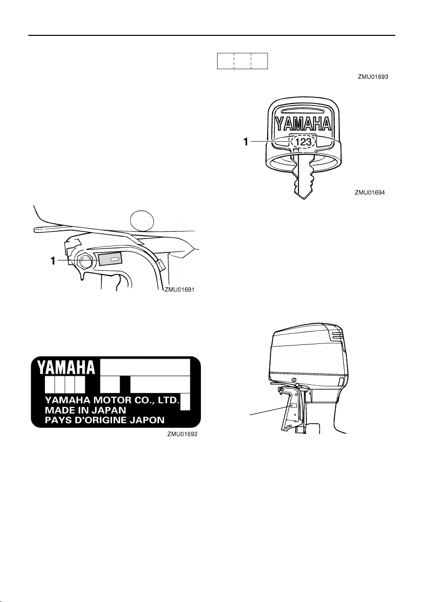
Outboard motor serial number .......... 1
Key number....................................... 1
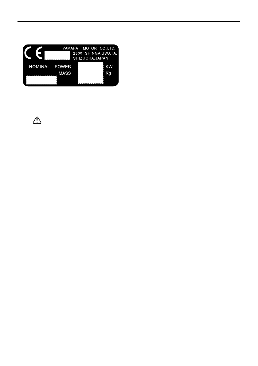
EC label........................................... 1
Safety information ........................... 2
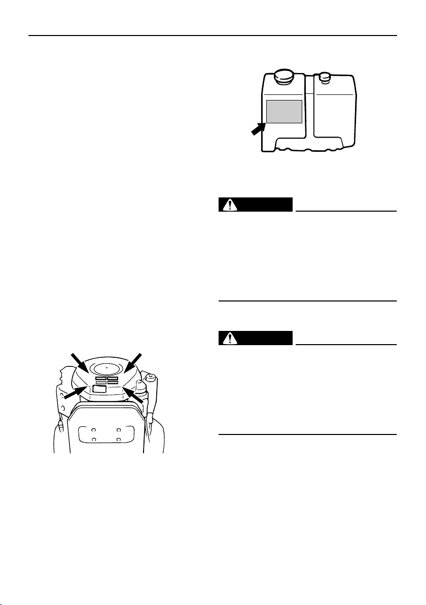
Important labels............................... 3
Warning labels .................................. 3
Fueling instructions ......................... 4
Gasoline............................................ 4
Engine oil .......................................... 4
Battery requirement......................... 4
Battery specifications ........................ 4
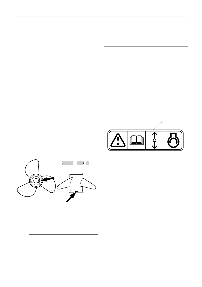
Propeller selection........................... 4
Start-in-gear protection ................... 5
Basic components ............................ 6
Main components............................ 6
Fuel tank ........................................... 6
Fuel joint ........................................... 7
Fuel gauge ........................................ 7
Fuel tank cap .................................... 7
Air vent screw ................................... 7
Remote control.................................. 7
Remote control lever......................... 7
Neutral interlock trigger..................... 8
Neutral throttle lever.......................... 8
Choke switch..................................... 8
Free accelerator................................ 9
Throttle friction adjuster..................... 9
Engine stop lanyard switch ............. 10
Choke knob for pull type ................. 11
Main switch ..................................... 11
Power trim and tilt switch on
remote control or tiller handle ....... 11
Power trim and tilt switch on bottom
engine cowling .............................. 11
Power trim and tilt switches (twin
binnacle type) ............................... 12
Trim tab with anode ........................ 12
Tilt support lever for power trim and
tilt or hydro tilt model..................... 13
Top cowling lock lever
(pull up type) ................................. 13
Digital tachometer ........................... 14
Oil level indicator (digital type) ........ 14
Overheat warning indicator (digital
type) .............................................. 14
Speedometer (digital type) .............. 15
Trim meter (digital type) .................. 15
Hour meter (digital type)..................16
Trip meter ........................................ 16
Clock ............................................... 16
Fuel gauge ...................................... 17
Fuel warning indicator ..................... 17
Low battery voltage warning
indicator ........................................ 17
Fuel management meter ................. 18
Fuel flow meter................................18
Fuel consumption meter..................19
Fuel economy.................................. 19
Twin-engine speed synchronizer ....19
Water separator warning
indicator ........................................ 20
Warning system ............................ 20
Overheat warning (twin engines) ....20
Oil level warning and oil filter
clogging warning ........................... 21
Operation ......................................... 23
Installation..................................... 23
Mounting the outboard motor .......... 23
Breaking in engine ........................ 24
Gasoline and engine oil mixing
chart (50:1).................................... 25
Procedure for oil injection models ... 25
Preoperation checks ..................... 25
Fuel ................................................. 25
Oil .................................................... 25
Controls ........................................... 26
Engine ............................................. 26
Operation after long period of
storage .......................................... 26
Filling fuel and engine oil .............. 26
Filling fuel for models without a
fuel joint......................................... 26
Filling oil for oil injection models...... 26
Oil level indicator operation............. 28
Operating engine .......................... 29
Feeding fuel (portable tank) ............ 29
Feeding fuel .................................... 29
Starting engine ................................ 30

Table of contents
Warming up engine ....................... 32
Choke start models ......................... 32
Shifting .......................................... 33
Forward (tiller handle and remote
control models) ............................. 33
Reverse (automatic reverse lock
and power trim and tilt models)..... 33
Stopping engine ............................ 34
Procedure ....................................... 34
Trimming outboard motor.............. 35
Adjusting trim angle ........................ 35
Adjusting boat trim .......................... 36
Tilting up and down ....................... 37
Procedure for tilting up.................... 37
Procedure for tilting down ............... 39
Cruising in shallow water .............. 39
Power trim and tilt models / power
tilt models...................................... 39
Cruising in other conditions........... 40
Maintenance..................................... 42
Specifications ................................ 42
Transporting and storing outboard
motor ........................................... 43
Storing outboard motor ................... 44
Procedure ....................................... 44
Lubrication (oil injection models)..... 45
Battery care..................................... 45
Cleaning the outboard motor .......... 46
Checking painted surface of
motor............................................. 46
Periodic maintenance.................... 46
Replacement parts.......................... 46
Maintenance chart .......................... 47
Greasing ......................................... 49
Cleaning and adjusting spark
plug ............................................... 49
Checking fuel system...................... 50
Inspecting fuel filter ......................... 51
Cleaning fuel filter ........................... 51
Inspecting idling speed ................... 52
Checking water in engine oil tank ... 52
Checking wiring and connectors ..... 52
Exhaust leakage ............................. 52
Water leakage................................. 53
Checking power trim and tilt
system........................................... 53
Checking propeller .......................... 54
Removing the propeller ................... 55
Installing the Propeller.....................55
Changing gear oil ............................ 56
Cleaning fuel tank ...........................57
Inspecting and replacing
anode(s)........................................ 57
Checking battery (for electric start
models) ......................................... 58
Connecting the battery .................... 59
Disconnecting the battery................60
Checking top cowling ...................... 60
Coating the boat bottom.................. 60
Trouble Recovery............................ 62
Troubleshooting ............................ 62
Temporary action in emergency ... 65
Impact damage ............................... 65
Running single engine.....................65
Replacing fuse ................................ 66
Power trim and tilt / power tilt will
not operate.................................... 66
Starter will not operate .................... 66
Emergency starting engine .............67
Engine fails to operate .................. 68
Ignition system malfunction............. 68
Low oil level warning activates........ 69
Treatment of submerged motor .... 70
Procedure........................................ 70

1
General information
EMU25170
Identification numbers record
EMU25183
Outboard motor serial number
The outboard motor serial number is
stamped on the label attached to the port
side of the clamp bracket.
Record your outboard motor serial number in
the spaces provided to assist you in ordering
spare parts from your Yamaha dealer or for
reference in case your outboard motor is sto-
len.
EMU25190
Key number
If a main key switch is equipped with the mo-
tor, the key identification number is stamped
on your key as shown in the illustration.
Record this number in the space provided for
reference in case you need a new key.
EMU25202
EC label
Engines affixed with this label conform to
certain portions of the European Parliament
directive relating to machinery. Refer to the
label and the EC Declaration of Conformity
for more details.
1. Outboard motor serial number location
1. Key number
1. EC label location
1
ZMU03900

General information
2
EMU25371
Safety information
●
Before mounting or operating the outboard
motor, read this entire manual. Reading it
should give you an understanding of the
motor and its operation.
●
Before operating the boat, read any own-
er’s or operator’s manuals supplied with it
and all labels. Be sure you understand
each item before operating.
●
Do not overpower the boat with this out-
board motor. Overpowering the boat could
result in loss of control. The rated power of
the outboard should be equal to or less
than the rated horsepower capacity of the
boat. If the rated horsepower capacity of
the boat is unknown, consult the dealer or
boat manufacturer.
●
Do not modify the outboard. Modifications
could make the motor unfit or unsafe to
use.
●
Incorrect propeller selection and incorrect
use may not only cause engine damage,
but also adversely affect fuel consumption.
Consult your dealer for correct use.
●
Never operate after drinking alcohol or tak-
ing drugs. About 50% of all boating fatali-
ties involve intoxication.
●
Have an approved personal flotation de-
vice (PFD) on board for every occupant. It
is a good idea to wear a PFD whenever
boating. At a minimum, children and non-
swimmers should always wear PFDs, and
everyone should wear PFDs when there
are potentially hazardous boating condi-
tions.
●
Gasoline is highly flammable, and its va-
pors are flammable and explosive. Handle
and store gasoline carefully. Make sure
there are no gas fumes or leaking fuel be-
fore starting the engine.
●
This product emits exhaust gases which
contain carbon monoxide, a colorless,
odorless gas which may cause brain dam-
age or death when inhaled. Symptoms in-
clude nausea, dizziness, and drowsiness.
Keep cockpit and cabin areas well ventilat-
ed. Avoid blocking exhaust outlets.
●
Check throttle, shift, and steering for prop-
er operation before starting the engine.
●
Attach the engine stop switch lanyard to a
secure place on your clothing, or your arm
or leg while operating. If you accidentally
leave the helm, the lanyard will pull from
the switch, stopping the engine.
●
Know the marine laws and regulations
where you will be boating - and obey them.
●
Stay informed about the weather. Check
weather forecasts before boating. Avoid
boating in hazardous weather.
●
Tell someone where you are going: leave
a Float Plan with a responsible person. Be
sure to cancel the Float Plan when you re-
turn.
●
Use common sense and good judgment
when boating. Know your abilities, and be
sure you understand how your boat han-
dles under the different boating conditions
you may encounter. Operate within your
limits, and the limits of your boat. Always
operate at safe speeds, and keep a careful
ZMU01696

General information
3
watch for obstacles and other traffic.
●
Always watch carefully for swimmers dur-
ing the engine operation.
●
Stay away from swimming areas.
●
When a swimmer is in the water near you
shift into neutral and shut off the engine.
●
Do not illegally discard empty containers
used to replace or replenish oil. For the
correct processing of empty containers,
consult the dealer where you purchased
the oil.
●
When replacing oils used to lubricate the
product (engine or gear oil), be sure to
wipe away any spilt oil. Never pour oil with-
out using a funnel or similar device. If nec-
essary, verify the necessary replacement
procedure with the dealer.
●
Never illegally discard (dump) the product.
Yamaha recommends consulting the deal-
er on discarding the product.
EMU25382
Important labels
EMU25395
Warning labels
EMU25401
Label
WARNING
EWM01260
●
Be sure shift control is in neutral before
starting engine. (except 2HP)
●
Do not touch or remove electrical parts
when starting or during operation.
●
Keep hands, hair, and clothes away
from flywheel and other rotating parts
while engine is running.
EMU25413
Label (counter rotation models)
WARNING
EWM01281
Use only a counterclockwise rotation
propeller with this engine.
Counterclockwise propellers are marked
with a letter “L” after the size indication.
The wrong type of propeller could cause
the boat to go in an unexpected direction,
which could lead to an accident.
EMU25451
Label
ENGINE OIL ONLY
●
Pour the engine oil into this oil tank, not
gasoline.
RECOMMENDED OIL:
YAMALUBE 2 STROKE OUTBOARD OIL or
ZMU05408
ZMU01948

General information
4
an equivalent TC-W3 certified ouboard oil.
WARNING
EWM01270
Do not add gasoline to the oil tank. Fire
explosion could result.
EMU25540
Fueling instructions
WARNING
EWM00010
GASOLINE AND ITS VAPORS ARE HIGH-
LY FLAMMABLE AND EXPLOSIVE!
●
Do not smoke when refueling, and keep
away from sparks, flames, or other
sources of ignition.
●
Stop engine before refueling.
●
Refuel in a well-ventilated area. Refuel
portable fuel tanks off the boat.
●
Take care not to spill gasoline. If gaso-
line spills, wipe it up immediately with
dry rags.
●
Do not overfill the fuel tank.
●
Tighten the filler cap securely after re-
fueling.
●
If you should swallow some gasoline,
inhale a lot of gasoline vapor, or get
gasoline in your eyes, get immediate
medical attention.
●
If any gasoline spills onto your skin, im-
mediately wash with soap and water.
Change clothing if gasoline spills on it.
●
Touch the fuel nozzle to the filler open-
ing or funnel to help prevent electro-
static sparks.
CAUTION:
ECM00010
Use only new clean gasoline which has
been stored in clean containers and is not
contaminated with water or foreign mat-
ter.
EMU25580
Gasoline
If knocking or pinging occurs, use a different
brand of gasoline or premium unleaded fuel.
EMU25650
Engine oil
If the recommended engine oil is not avail-
able, another 2-stroke engine oil with an
NMMA-certified TC-W3 rating may be used.
EMU25690
Battery requirement
CAUTION:
ECM01060
Do not use a battery that does not meet
the specified capacity. If a battery which
does not meet specifications is used, the
electric system could perform poorly or
be overloaded, causing electric system
damage.
For electric start models, choose a battery
which meets the following specifications.
EMU25720
Battery specifications
EMU25742
Propeller selection
The performance of your outboard motor will
Recommended gasoline:
Regular unleaded gasoline with a min-
imum octane rating of 90 (Research
Octane Number).
Recommended engine oil:
YAMALUBE 2-stroke outboard motor
oil
Minimum cold cranking amps (CCA/EN):
430.0 A
Minimum rated capacity (20HR/IEC):
70.0 Ah

General information
5
be critically affected by your choice of propel-
ler, as an incorrect choice could adversely
affect performance and could also seriously
damage the motor. Engine speed depends
on the propeller size and boat load. If engine
speed is too high or too low for good engine
performance, this will have an adverse effect
on the engine.
Yamaha outboard motors are fitted with pro-
pellers chosen to perform well over a range
of applications, but there may be uses where
a propeller with a different pitch would be
more appropriate. For a greater operating
load, a smaller-pitch propeller is more suit-
able as it enables the correct engine speed
to be maintained. Conversely, a larger-pitch
propeller is more suitable for a smaller oper-
ating load.
Yamaha dealers stock a range of propellers,
and can advise you and install a propeller on
your outboard that is best suited to your ap-
plication.
NOTE:
Select a propeller which will allow the engine
to reach the middle or upper half of the oper-
ating range at full throttle with the maximum
boat load. If operating conditions such as
light boat loads then allow the engine r/min to
rise above the maximum recommended
range, reduce the throttle setting to maintain
the engine in the proper operating range.
For instructions on propeller removal and in-
stallation, see page 54.
EMU25760
Start-in-gear protection
Yamaha outboard motors affixed with the
pictured label or Yamaha-approved remote
control units are equipped with start-in-gear
protection device(s). This feature permits the
engine to be started only when it is in neutral.
Always select neutral before starting the en-
gine.
1. Propeller diameter in inches
2. Propeller pitch in inches
3. Type of propeller (propeller mark)
ZMU04608
-
x
123
1. Start-in-gear protection label
ZMU01713
1

6
Basic components
EMU25797
Main components
NOTE:
* May not be exactly as shown; also may not be included as standard equipment on all mod-
els.
150F, L150F, 200F, L200F
EMU25802
Fuel tank
If your model was equipped with a portable
fuel tank, its function is as follows.
WARNING
EWM00020
The fuel tank supplied with this engine is
1
3
4
5
6
7
8
9
11
12
10 14
15 16 17
18 19 20
2
13
9
ZMU04556
1. Power trim and tilt switch
2. Tilt support lever
3. Anti-cavitation plate
4. Trim tab (anode)
5. Propeller
6. Cooling water inlet
7. Anode
8. Clamp bracket
9. Top cowling lock lever
10. Choke knob
11. Top cowling
12. Cooling water pilot hole
13. Remote control box (side mount type)*
14. Remote control box (binnacle mount type)*
15. Switch panel (for use with binnacle type)*
16. Digital tachometer*
17. Digital speedometer*
18. Fuel management meter*
19. Fuel tank*
20. Remote oil tank

Basic components
7
its dedicated fuel reservoir and must not
be used as a fuel storage container. Com-
mercial users should conform to relevant
licensing or approval authority regula-
tions.
EMU25830
Fuel joint
This joint is used to connect the fuel line.
EMU25841
Fuel gauge
This gauge is located on either the fuel tank
cap or on the fuel joint base. It shows the ap-
proximate amount of fuel remaining in the
tank.
EMU25850
Fuel tank cap
This cap seals the fuel tank. When removed,
the tank can be filled with fuel. To remove the
cap, turn it counterclockwise.
EMU25860
Air vent screw
This screw is on the fuel tank cap. To loosen
the screw, turn it counterclockwise.
EMU26180
Remote control
The remote control lever actuates both the
shifter and the throttle. The electrical switch-
es are mounted on the remote control box.
EMU26190
Remote control lever
Moving the lever forward from the neutral po-
sition engages forward gear. Pulling the le-
ver back from neutral engages reverse. The
engine will continue to run at idle until the le-
ver is moved about 35° (a detent can be felt).
Moving the lever farther opens the throttle,
1. Fuel joint
2. Fuel gauge
3. Fuel tank cap
4. Air vent screw
ZMU02284
3
1
4
2
1. Power trim and tilt switch
2. Remote control lever
3. Neutral interlock trigger
4. Neutral throttle lever
5. Main switch / choke switch
6. Engine stop lanyard switch
7. Throttle friction adjuster
1. Remote control lever
2. Power trim and tilt switch
3. Free accelerator
4. Throttle friction adjuster
2
3
2
1
4
ZMU04569

Basic components
8
and the engine will begin to accelerate.
EMU26201
Neutral interlock trigger
To shift out of neutral, first pull the neutral in-
terlock trigger up.
EMU26211
Neutral throttle lever
To open the throttle without shifting into ei-
ther forward or reverse, put the remote con-
trol lever in the neutral position and lift the
neutral throttle lever.
NOTE:
The neutral throttle lever will operate only
when the remote control lever is in neutral.
The remote control lever will operate only
when the neutral throttle lever is in the closed
position.
EMU26221
Choke switch
To activate the choke system, press in the
main switch while the key is turned to the
1. Neutral “ ”
2. Forward “ ”
3. Reverse “ ”
4. Shift
5. Fully closed
6. Throttle
7. Fully open
1. Neutral “ ”
2. Forward “ ”
3. Reverse “ ”
4. Shift
5. Fully closed
6. Throttle
7. Fully open
N
1
F
7
6
2
R
3
44
6
5
7
5
ZMU04573
1. Neutral interlock trigger
1. Fully open
2. Fully closed

Basic components
9
“ ” (on) or “ ” (start) position. The
choke system will then supply the rich fuel
mixture required to start the engine. When
the key is released, the choke will switch off
automatically.
EMU26232
Free accelerator
To open the throttle without shifting into ei-
ther forward or reverse, push the free accel-
erator button and move the remote control
lever.
NOTE:
●
The free accelerator button can only be
used when the remote control lever is in
the neutral position.
●
After the button is pushed, the throttle be-
gins to open after the remote control lever
is moved at least 35°.
●
After using the free accelerator, return the
remote control lever to the neutral position.
The free accelerator button will return au-
tomatically to its set position. The remote
control will then engage forward and re-
verse normally.
EMU25971
Throttle friction adjuster
A friction device provides adjustable resis-
tance to movement of the throttle grip or the
remote control lever, and can be set accord-
ing to operator preference.
To increase resistance, turn the adjuster
clockwise. To decrease resistance, turn the
adjuster counterclockwise.
WARNING
EWM00031
Do not overtighten the friction adjuster. If
there is too much resistance, it could be
difficult to move the remote control lever
ZMU03160
START
ON
ZMU04593
1. Fully open
2. Fully closed
3. Free accelerator
1
3
2
ZMU04575

Basic components
10
or throttle grip, which could result in an
accident.
When constant speed is desired, tighten the
adjuster to maintain the desired throttle set-
ting.
EMU25990
Engine stop lanyard switch
The lock plate must be attached to the en-
gine stop switch for the engine to run. The
lanyard should be attached to a secure place
on the operator’s clothing, or arm or leg.
Should the operator fall overboard or leave
the helm, the lanyard will pull out the lock
plate, stopping ignition to the engine. This
will prevent the boat from running away un-
der power.
WARNING
EWM00120
●
Attach the engine stop switch lanyard
to a secure place on your clothing, or
your arm or leg while operating.
●
Do not attach the lanyard to clothing
that could tear loose. Do not route the
lanyard where it could become entan-
gled, preventing it from functioning.
●
Avoid accidentally pulling the lanyard
during normal operation. Loss of en-
gine power means the loss of most
steering control. Also, without engine
power, the boat could slow rapidly. This
could cause people and objects in the
boat to be thrown forward.
NOTE:
The engine cannot be started with the lock
plate removed.
ZMU04646
1. Lanyard
2. Lock plate
1. Lanyard
2. Lock plate
ONSTART
OFF
ONSTART
OFF
1
ZMU04564
2

Basic components
11
EMU26011
Choke knob for pull type
To supply the engine with the rich fuel mix-
ture required to start, pull out this knob.
EMU26090
Main switch
The main switch controls the ignition system;
its operation is described below.
●
“”
(off)
With the main switch in the “ ” (off) posi-
tion, the electrical circuits are off, and the key
can be removed.
●
“”
(on)
With the main switch in the “ ” (on) posi-
tion, the electrical circuits are on, and the key
cannot be removed.
●
“”
(start)
With the main switch in the “ ” (start) po-
sition, the starter motor turns to start the en-
gine. When the key is released, it returns
automatically to the “ ” (on) position.
EMU26141
Power trim and tilt switch on remote
control or tiller handle
The power trim and tilt system adjusts the
outboard motor angle in relation to the tran-
som. Pressing the switch “ ” (up) trims the
outboard motor up, then tilts it up. Pressing
the switch “ ” (down) tilts the outboard mo-
tor down and trims it down. When the switch
is released, the outboard motor will stop in its
current position.
NOTE:
For instructions on using the power trim and
tilt switch, see pages 35 and 37.
EMU26151
Power trim and tilt switch on bottom
engine cowling
The power trim and tilt switch is located on
the side of the bottom engine cowling. Press-
ing the switch “ ” (up) trims the outboard
ZMU03903
ON
OFF START
ON
OFF START
ZMU04566

Basic components
12
motor up, then tilts it up. Pressing the switch
“ ” (down) tilts the outboard motor down
and trims it down. When the switch is re-
leased, the outboard motor will stop in its
current position.
WARNING
EWM01030
Use the power trim and tilt switch located
on the bottom engine cowling only when
the boat is at a complete stop with the en-
gine off. Attempting to use this switch
while the boat is moving could increase
the risk of falling overboard and could
distract the operator, increasing the risk
of collision with another boat or an obsta-
cle.
NOTE:
For instructions on using the power trim and
tilt switch, see page 37.
EMU26161
Power trim and tilt switches (twin
binnacle type)
The power trim and tilt system adjusts the
outboard motor angle in relation to the tran-
som. Pushing the switch “ ” (up) trims the
outboard motor up, then tilts it up. Pressing
the switch “ ” (down) tilts the outboard mo-
tor down and trims it down. When the switch
is released, the outboard motor will stop in its
current position.
NOTE:
●
On the dual engine control, the switch on
the remote control grip controls both out-
board motors at the same time.
●
For instructions on using the power trim
and tilt switches, see pages 35 and 37.
EMU26241
Trim tab with anode
The trim tab should be adjusted so that the
steering control can be turned to either the
right or left by applying the same amount of
force.
WARNING
EWM00840
An improperly adjusted trim tab could
cause difficult steering. Always test run
after the trim tab has been installed or re-
placed to be sure steering is correct. Be
sure you have tightened the bolt after ad-
justing the trim tab.
If the boat tends to veer the left (port side),
turn the trim tab rear end to the port side “A”
in the figure. If the boat tends to veer the right
(starboard side), turn the trim tab end to the
starboard side “B” in the figure.
CAUTION:
ECM00840
The trim tab also serves as an anode to
UP
DN
ZMU03517
1. Power trim and tilt switch
DN
UP
1
ZMU04568

Basic components
13
protect the engine from electrochemical
corrosion. Never paint the trim tab as it
will become ineffective as an anode.
EMU26340
Tilt support lever for power trim and
tilt or hydro tilt model
To keep the outboard motor in the tilted up
position, lock the tilt support lever to the
clamp bracket.
EMU26382
Top cowling lock lever (pull up type)
To remove the engine top cowling, pull up
the lock lever(s) and lift off the cowling.
When installing the cowling, check to be sure
it fits properly in the rubber seal. Then lock
the cowling by moving the lever(s) down-
ward.
1. Trim tab
2. Bolt
3. Cap
1
2
3
ZMU02525
A
B
A
BZMU01863
1. Tilt support lever
1. Top cowling lock lever(s)
ZMU03947
1
ZMU03904
1

Basic components
14
EMU26491
Digital tachometer
The tachometer shows the engine speed
and has the following functions.
NOTE:
All segments of the display will light momen-
tarily after the main switch is turned on and
will return to normal thereafter.
NOTE:
The water separator and engine trouble
warning indicators only operate when the en-
gine is equipped with the appropriate func-
tions.
EMU26550
Oil level indicator (digital type)
This indicator shows the engine oil level. If
the oil level falls below the lower limit, the
warning indicator will start to blink. For fur-
ther information, see page 21.
CAUTION:
ECM00030
Do not operate the engine without oil. Se-
rious engine damage will occur.
EMU26581
Overheat warning indicator (digital
type)
If the engine temperature rises too high, the
warning indicator will start to blink. For fur-
ther information on reading the indicator, see
page 20.
CAUTION:
ECM00050
Do not continue to run the engine if the
overheat warning indicator is on. Serious
engine damage will occur.
1. Top cowling lock lever(s)
1. Tachometer
2. Trim meter
3. Hour meter
4. Oil level indicator
5. Overheat warning indicator
6. Water separator warning indicator
7. Engine trouble warning indicator
8. Set button
9. Mode button
ZMU03905
1
6
7
2
4
9
8
5
3
1
ZMU01958
1. Oil level indicator
1ZMU01867

Basic components
15
EMU26600
Speedometer (digital type)
This gauge shows the boat speed.
NOTE:
After the main switch is first turned on, all
segments of the display come on as a test.
After a few seconds, the gauge will change
to normal operation. Watch the gauge when
turning on the main switch to make sure all
segments come on.
NOTE:
The speedometer displays km/h, mph, or
knots, according to operator preference. Se-
lect the desired unit of measurement by set-
ting the selector switch on the back of the
gauge. See the illustration for settings.
EMU26620
Trim meter (digital type)
This meter shows the trim angle of your out-
board motor.
NOTE:
●
Memorize the trim angles that work best
for your boat under different conditions.
Adjust the trim angle to the desired using
the power trim and tilt switch.
●
If the trim angle of your motor exceeds the
trim operating range, the top segment on
the trim meter display will blink.
1. Overheat warning indicator
1. Speedometer
2. Fuel gauge
3. Trip meter/clock/voltmeter
4. Warning indicator(s)
1
ZMU01868
1. Cap
2. Selector switch (for speed unit)
3. Selector switch (for fuel sensor)
ZMU01869
Other manuals for 150F
1
This manual suits for next models
3
Table of contents
Other Yamaha Outboard Motor manuals