Craftsman 291.376400 User manual
Other Craftsman Lawn Mower manuals
Craftsman
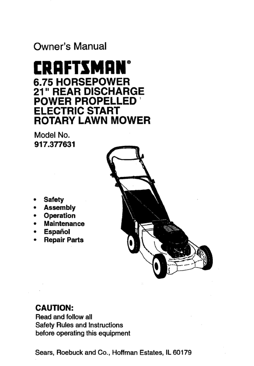
Craftsman 917.377631 User manual
Craftsman
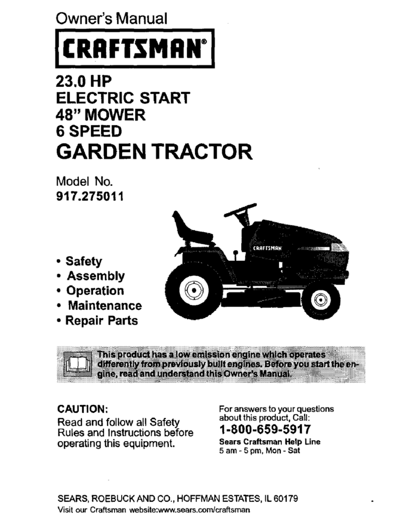
Craftsman 917.275011 User manual

Craftsman
Craftsman 917.376652 User manual
Craftsman
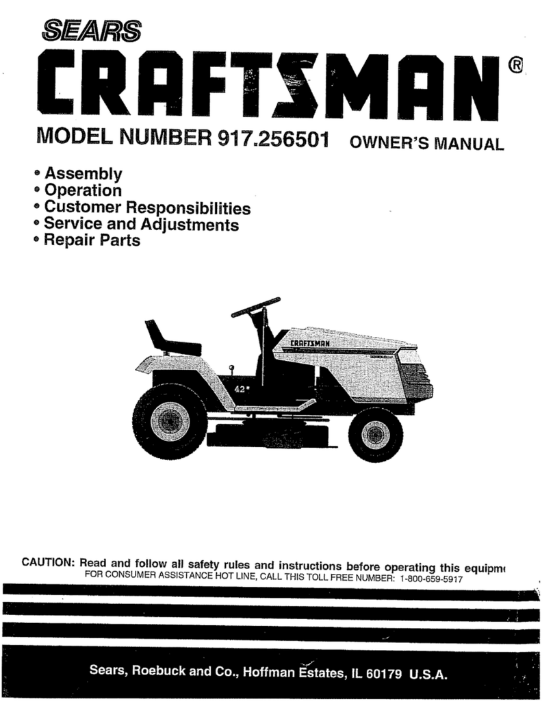
Craftsman 917.256501 User manual
Craftsman
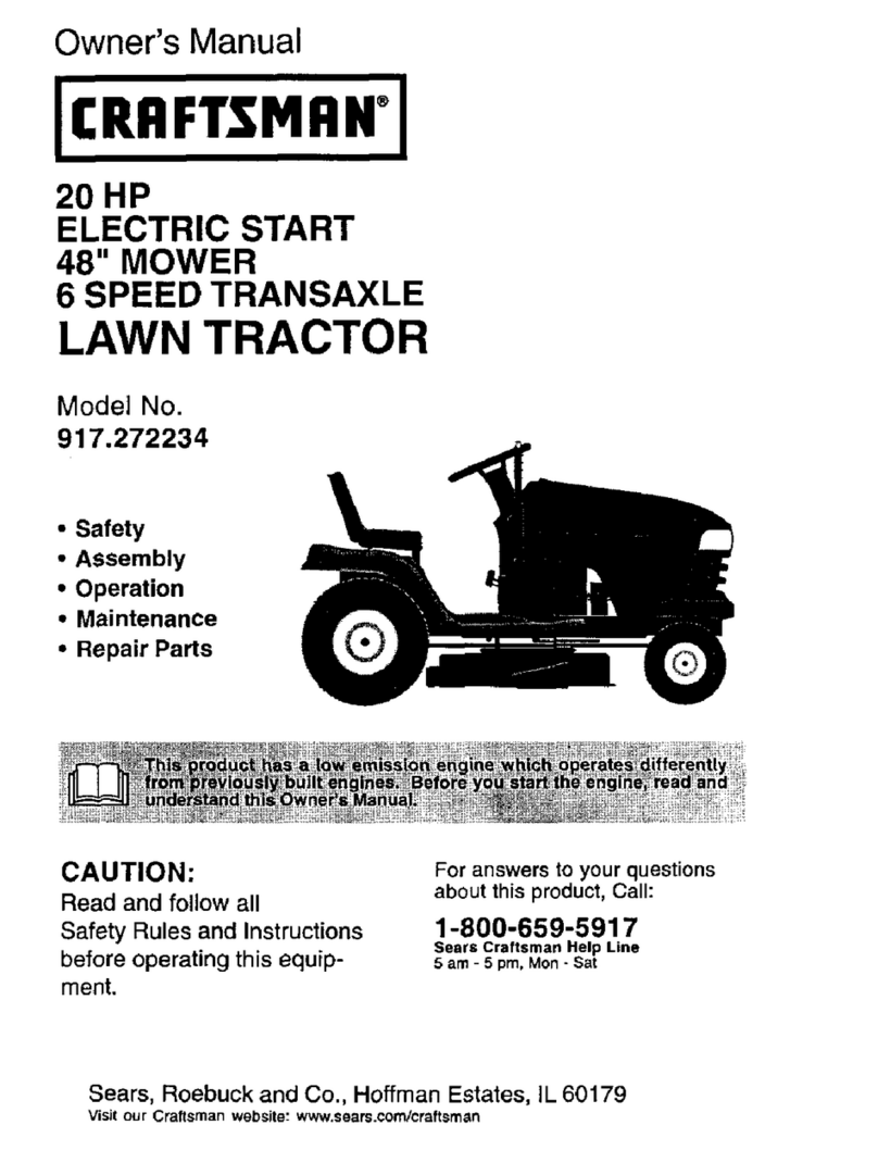
Craftsman 917.272234 User manual
Craftsman
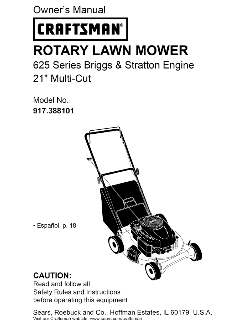
Craftsman 917.388101 User manual
Craftsman
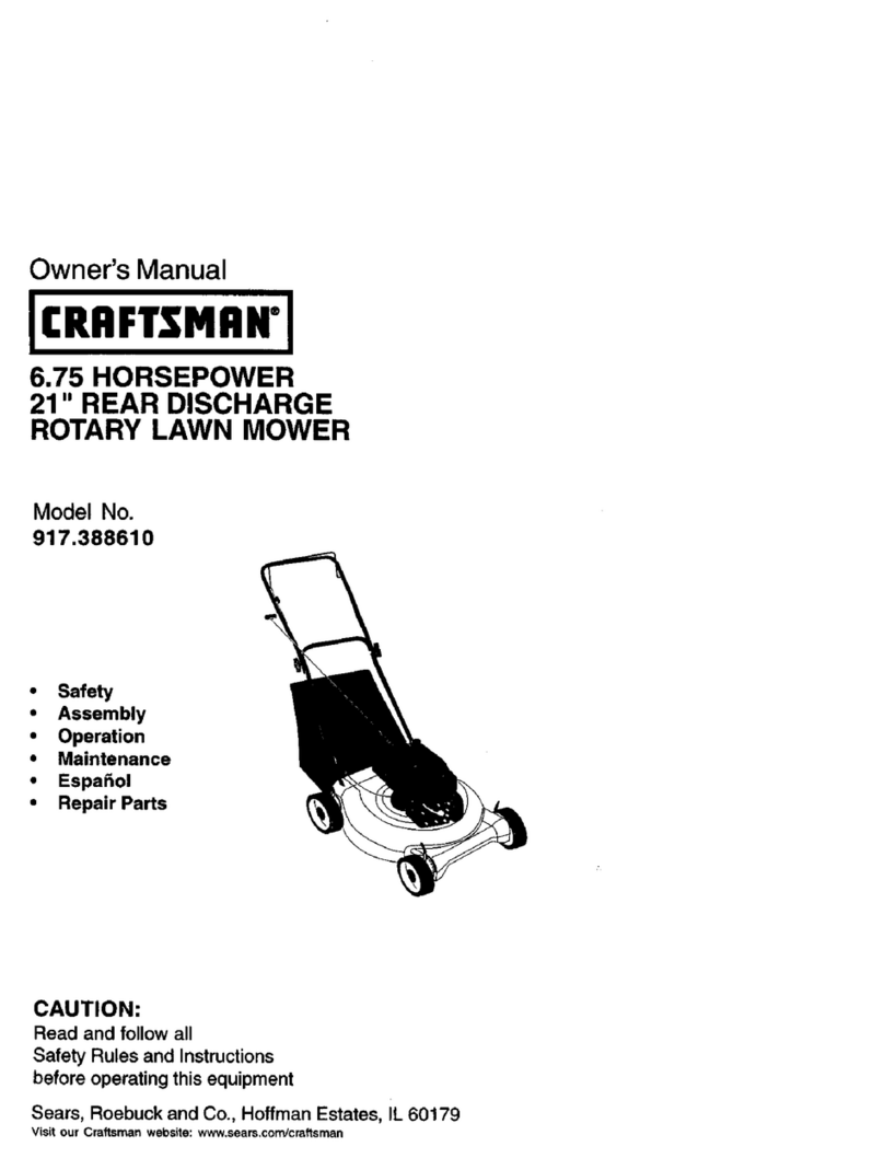
Craftsman 917.388610 User manual
Craftsman
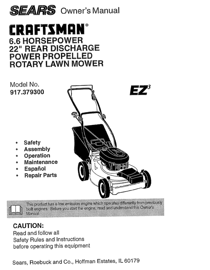
Craftsman 917.379300 User manual
Craftsman
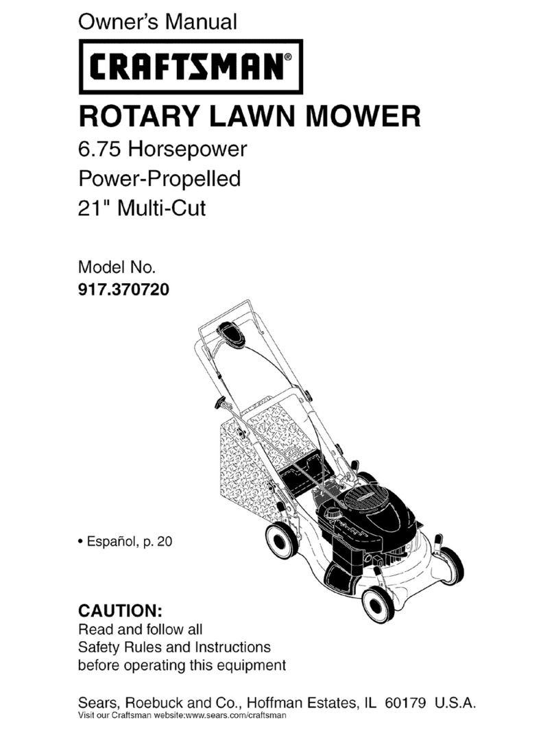
Craftsman 917.370720 User manual
Craftsman
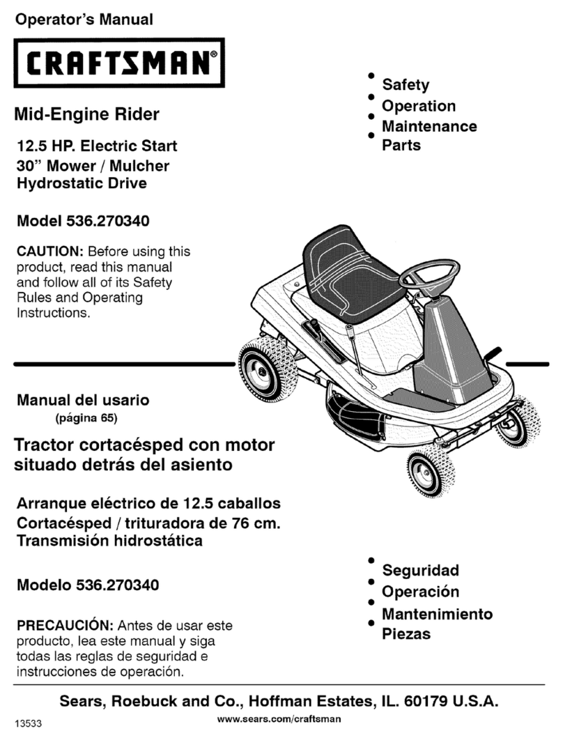
Craftsman 536.270340 User manual

Craftsman
Craftsman 917.376990 User manual

Craftsman
Craftsman 25447 User manual
Craftsman
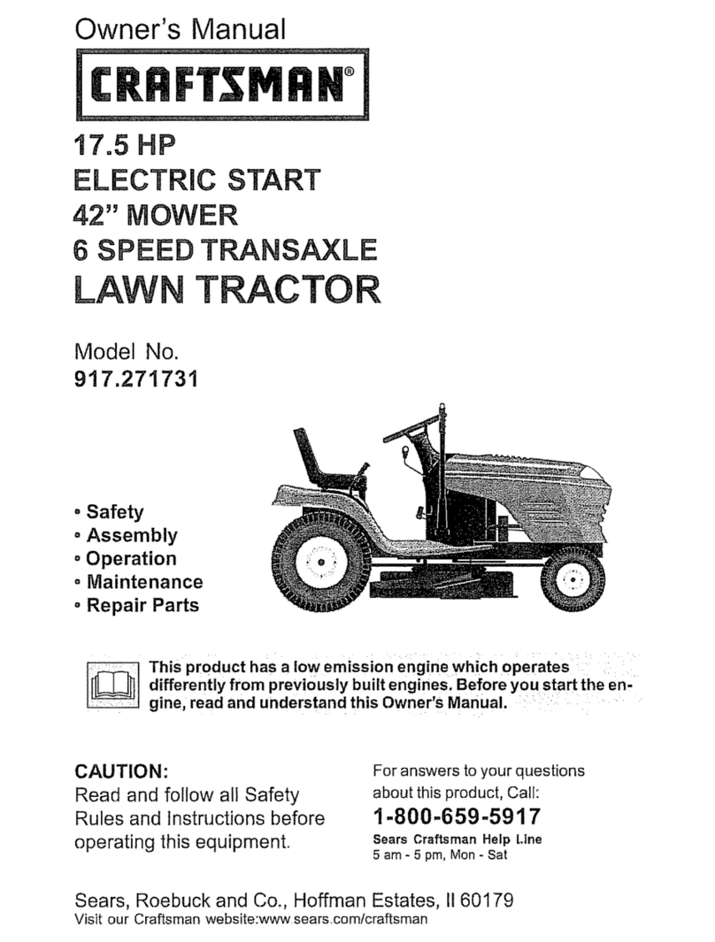
Craftsman 917.271731 User manual
Craftsman
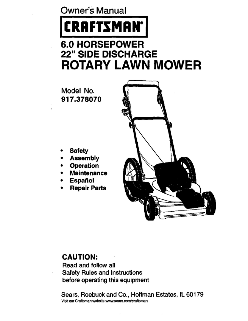
Craftsman 917.378070 User manual
Craftsman
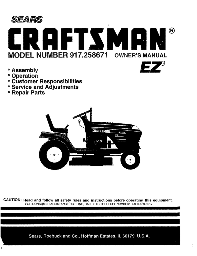
Craftsman EZ3 917.258671 User manual
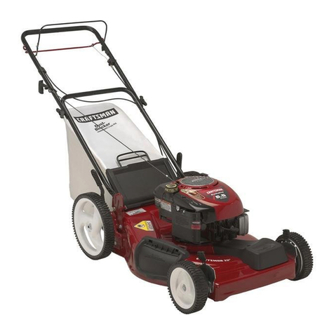
Craftsman
Craftsman 917.376080 User manual

Craftsman
Craftsman 944.364153 User manual
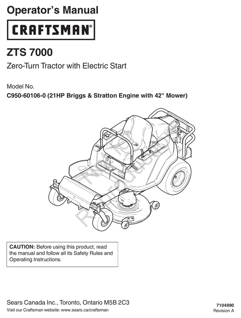
Craftsman
Craftsman Remote Controller User manual
Craftsman
Craftsman 917.27662 User manual
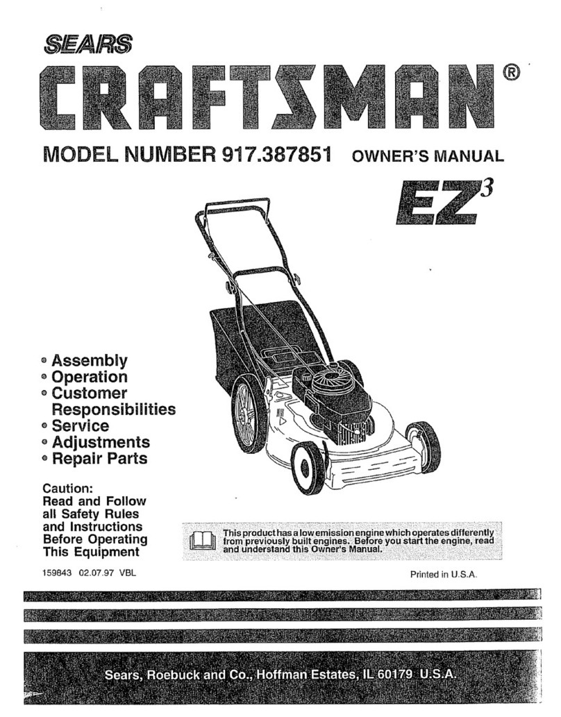
Craftsman
Craftsman 917.387851 User manual
Popular Lawn Mower manuals by other brands

DEWEZE
DEWEZE ATM-725 Operation and service manual

Weed Eater
Weed Eater 180083 owner's manual

Husqvarna
Husqvarna Poulan Pro PP185A42 Operator's manual

Better Outdoor Products
Better Outdoor Products Quick Series Operator's manual

Cub Cadet
Cub Cadet 23HP Z-Force 60 Operator's and service manual

MTD
MTD 795, 792, 791, 790 Operator's manual
