PROTEA BG 760 User manual
PROTEA TURF EQUIPMENT
Manufacturers of Industrial Lawnmowers, Scarifiers & Sodcutters
Reg. No. CK 1989/023716/23
Vat Reg. No. 4830119907
P.O. Box 1673
Bedfordview
2008
www.proteamachines.com
32 Shaft Rd
Knights, Germiston
Tel: +2711 828 9935
PROTEA BG760
ELECTRIC BOWLING GREEN MOWER

Tel: +2711 828 9935
Mobile: +2782 458 7257
P.O. Box 1673 32 Shaft Road
Bedfordview Knights
2008 Germiston
Gauteng Gauteng
South Africa South Africa
Physical Address
Contact Numbers
Email: [email protected]
CONTACT DETAILS:
Email: [email protected]
Email: sean@proturf.co.za
For further information on any Protea products, please visit our website www.proteamachines.com
Postal Address

SPECIFICATIONS
MOTORS CUTTING CYLINDER
Standard 220 Volt 1,5kw 1 phase 762mm long x 152mm diameter
Other single or three phase motors (30” x 6”) 16 single helix
available on request reversible blades; each blade
25mm (1”) x 8 gauge.
TRANSMISSION BOTTOM BLADE
Twin “V” Belt to countershaft, then by Precision ground to less than 1.8mm
Heavy duty drive chains and sprockets to (.070”) at the cutting edge and
attached roller and cutter attached to the soleplate by 9
countersunk machine screws.
1mm Blade also available.
ADJUSTMENTS
Height of cut: by independent micro-adjusters
with dual lock nuts.
Cutter to bottom blade: By independent
micro-adjusters with dual lock nuts
(Precision setting bar supplied)
GEARBOX
16 Bladed Cutting Cylinder
Heavy-duty gears, 2 speed on traverse constant
Cutter revolutions. High gear 5.15km/h (3.2mph).
Clip frequency 200 clips per meter
(186 clips per yard). Low gear 3.88km/h (2.1mph)
Clip frequency 291 clips per meter (276 clips per yard)
MASS BEARINGS
(Complete with Grassbox) Sealed ball races fitted throughout
110/220 Volt –164kg (362lbs) (Prepacked with Lubricant)

1. Know your controls. Read the owner's manual 13. Stop the engine whenever you leave the
carefully. Learn how to stop engine quickly in the mower unattended, even for a moment.
event of an emergency.
14. Stop the engine before pushing the mower
2. Ensure the lawn is clear of sticks, stones, across gravel drives, walks or roads.
wire and debris. They could be thrown
by the blade. 15. Do not allow children or people
unfamiliar with these instructions operate
3. Stop the engine and disconnect the spark plug wire the mower.
before checking or working on the mower.
16. On slopes or wet grass, be extra careful of
4. Before use, always visually inspect to see that the your footing.
blade bolts and cutter assembly are not worn or
damaged. Replace worn or damaged blades and 17. Never cut grass by pulling the mower towards
bolts in sets to preserve balance. you.
Damaged blades and worn bolts are a
major hazard. 18. Never use an electrically powered mower in
the rain or when the grass is wet.
5. Check all nuts, bolts and screws often. Always
ensure the mower is in a safe operating condition. 19. Be extremely careful when using a ride on
Use only replacement parts made and guaranteed
mower on slopes.
by the original manufacturer of your mower.
20. Never leave wind-up starters in a wound
6. Add fuel BEFORE starting engine. Avoid spilling condition.
gasoline and do not fill the tank while the engine is
running or while you are smoking. 21. Do not over speed the engine or alter governor
settings. Excessive speed is dangerous
7. Do not mow whilst people, especially children and shortens mower life.
or pets, are in the mowing area.
22. It is advisable to wear suitable eye protection
8. Never use the mower unless the grass catcher , when operating a mower.
or guards provided by the manufacturer,
are in position. 23. Turn the fuel off at the conclusion of mowing
and reduce the throttle setting during
9. Do not mow barefoot or in open sandals. engine run-out.
Wear long trousers and heavy shoes.
24. Store fuel in a cool place in a container
10. Disengage all blade and drive clutches before specifically designed for the purpose.
starting.
25. Never pick up or carry a mower when it is
11. Start the engine carefully with feet well away operating.
from the blades.
12. Do not operate the engine in a confined space where
exhaust fumes (carbon monoxide) can collect.
LAWNMOWER SAFETY PRECAUTIONS
1

1
MAINTENANCE AND ADJUSTMENT
Normal Speed: 5.15km/h (3.2 mp/h) –200 clips per meter (186 clips per yard)
Low Speed: 3.88km/h (2.1 mp/h) –291 clips per meter (276 clips per yard)
Speed Control
To change speed, stop motor and move
ribbed sliding sleeve (A) inwards to engage
normal speed, outwards for low speed as
required. It may be necessary to twist the
sleeve or countershaft backwards and
forwards slightly whilst sliding the sleeve
into position to allow the gear teeth to line
up and mesh fully.
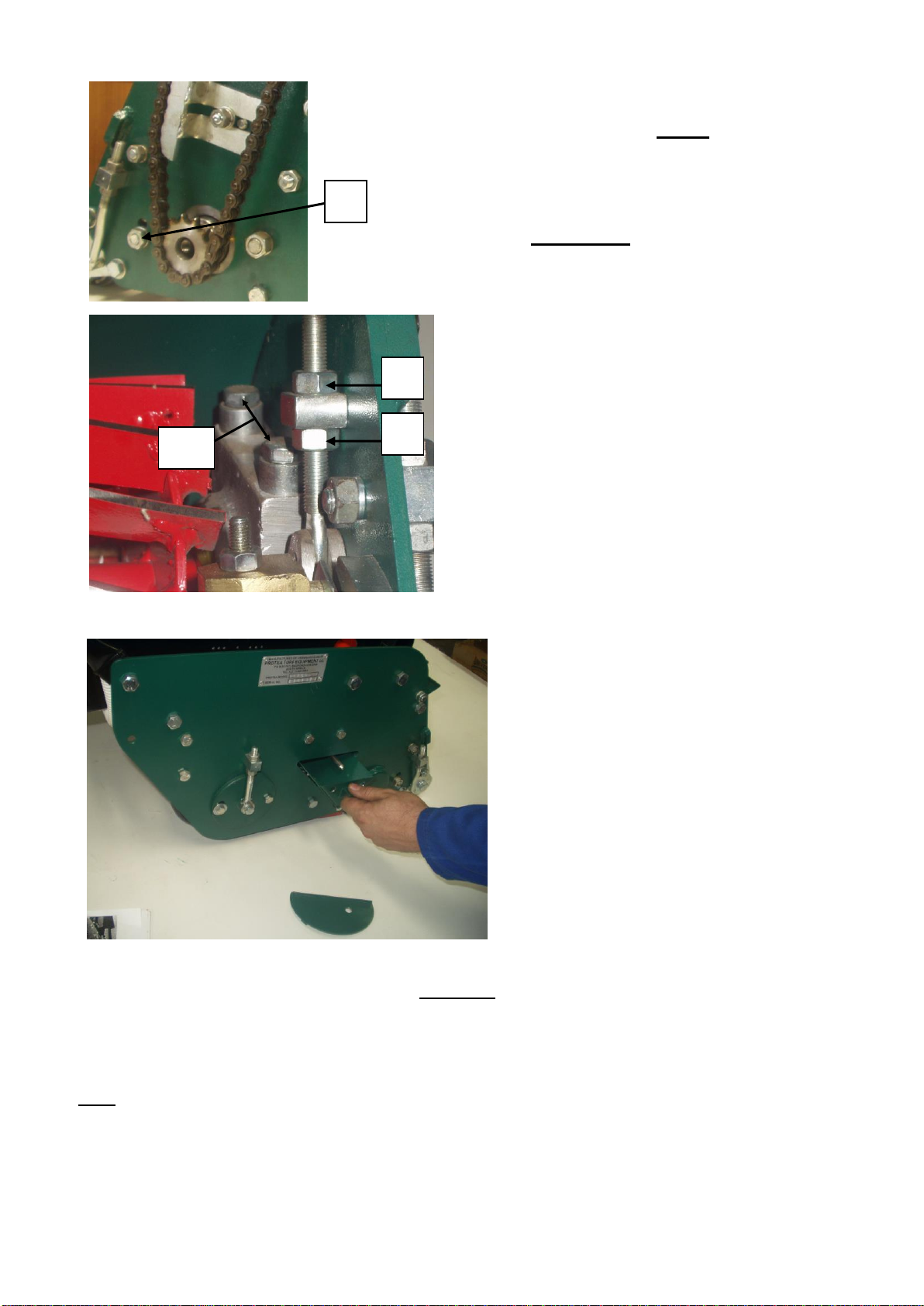
Height Adjustment
To cut lower,
slacken quadrant
clamp bolt nuts (1),
also the lower
adjusting screw nut
(2). Then tighten top
adjusting screw nut
(3) until desired
height of cut is
obtained. To cut
higher, reverse
procedure. Re-
tighten all nuts after
desired setting is
obtained
Refer setting gauge
instructions.
A
9
3
1
14
14
4
2
7
8

2
To check the mower for alignment –Your mower is designed to produce
the perfectly flat cut that is required for a top quality green. Ridging or
stepping between cuts means that the height of cut is unevenly set or more
likely, that the mower is “out of square”. That is, the rear roller is not
perfectly in line with the cutting edge of the bottom blade. This condition
can be brought about by transport of the mower or undue stress caused by
bumping while moving the mower from the equipment shed onto the green.
Re-alignment can be achieved by different means but the recommend
procedure is
1. Lay mower back on the handle
2. Chalk the thin front edge of the bottom blade about 6” of its length
at both ends.
3. With the front roller remaining in approximately its normal height
setting, “sight” the bottom of the front roller relative to the chalked
cutting edge of the blade
4. Adjust the front roller into exact alignment with the cutting edge,
continually sighting while adjustment proceeds
5. Lock the roller and re-check
6. Now use your height setting bar as an alignment tool by placing the
bar against the front roller and the rear roller on the extreme LEFT
HAND SIDE (Chain cover Side)
7. Adjust the setting bar screw so that it just contacts the bottom blade
cutting edge.
8. Test the right hand side of the rear rollers with the same setting, and
adjust the rear roller up or down Loosen (A) until the same screw
contact is achieved on the blade.
9. As the movement of the rear drum could affect the original L.H.S
setting slightly, reset he screw at the L.H.S. and recheck the R.H.S.
10. All elements of you machine will now be in perfect alignment.
11. After tightening all adjustments a final check should be made.
12. The required height of cut can now be checked and set in the
normal manner
While the procedure may seem complicated it is in fact very simple to
perform and can be carried out in less than 15 minutes. The sighting is easy
and accurate because it is done from the front roller, which is nearest to the
operator. A machine that is “true” will pay dividends by precision cutting
of your green.
Setting Gauge
This illustrates the method of setting the gauge to
the height of cut, where in this instance height of
cut is a 20-cent piece and a 5-cent coin. The
distance between the setting gauge bar and the
underside of the adjustable screw head represents
the height of cut. Lock the screw in the desired
position with the wing nut. To use the setting
gauge, rest it against the underside of the front and
rear roller, as illustrated, and by adjusting the front
roller, the desired height of cut will be obtained
when the underside of the screw head lightly
touches the top cutting edge of the bottom blade
across its full width.
Note: When using the setting gauge, take
care not to force the head of the adjusting
screw onto the bottom blade, as this could
distort the blade and affect the setting.
A
3
Cutter
To adjust the cutter setting, slacken cutter
housing nuts (4) on each side of the machine,
and proceed as follows;
Adjustment: Slacken the top nuts (5) on
adjusting screws. Then by tightening the
bottom nuts (6), the cutter is lowered on to the
bottom blade. To raise the cutter, loosen the
bottom nuts and tighten the top nuts.
Remember to re-tighten cutter housing nuts.
Always adjust cutter to bear very lightly on
bottom blade. If the cutter rubs harshly on the
bottom blade, there will be excessive wear of
both cutter blades and bottom blade, and an
unnecessarily heavy load on the power unit.
A grass trough is
incorporated that can be
adjusted closely to the
rear drum so that grass
and dirt build up is
scraped from the drum
and caught in the trough.
To empty:
Remove the cover plate from the trough opening in the side frame. The cover unclips by pivoting it
upwards. Withdraw the trough, as illustrated. When replacing, the end of the trough could come into
contact with its adjusting screw, when halfway in. A twisting action will allow the bottom edge of the
trough to clear the screw and push right in. Replace the cover plate.
Note: The trough can be withdrawn more easily if the deflector clamp bolts are loosened and the
deflector lowered to allow extra clearance.
Adjustment –The adjusting screw can only be operated when the trough is removed as it is located under
the center of the trough. To adjust trough closer to roller, release lock nut and lower screw lightly –to
move it away, raise screw slightly. Replace trough and check clearance from the drum. If satisfactory,
withdraw trough and tighten the lock nut.
10
6
5
4
4
Reversing Cutter:
A feature of this machine is that the cylinder may be easily removed, reversed end for end
and replaced. This provides a new keen cutting edge. If the bottom blade is badly worn, it
should be replaced at the same time that the cutting cylinder is reversed or replaced.
To withdraw cutter from machine, first remove cutter chain (7), sprocket (8) and grass
deflector (9), refer illustration PAGE 1. The sprocket is removed by inserting tommy bar in
the hole of the sprocket and giving the tommy bar a sharp tap with hammer, NOTE: The
sprocket has a left hand thread, to unscrew, turn in a clockwise direction. Remove the
grass deflector and the deflector-supporting bar. Remove the cutter hanger caps by undoing
the holding bolts (10) at each side of the machine. Then the cutter may be taken from the
machine by lifting and moving to the chain side of the machine. The opposite side will then
clear side frame. Continue with a diagonal lift to complete removal. Remove the nut from the
end of the cutter (it has a left hand thread). Reposition this nut on the other end of the cutter.
Turn the cutter end for end and replace in the machine. Then reverse operations used to
remove cutter from machine. Replace all bolts and tighten firmly. After reversing cutter it
will be necessary to adjust the same. Also see detail on chain adjustment
Important:
When reversing or replacing the cutter do not remove the cutter bearing
hangers. Remove the bearing caps only as per instruction. The bearing
caps must not be changed over; each cap must be replaced in its original
location.
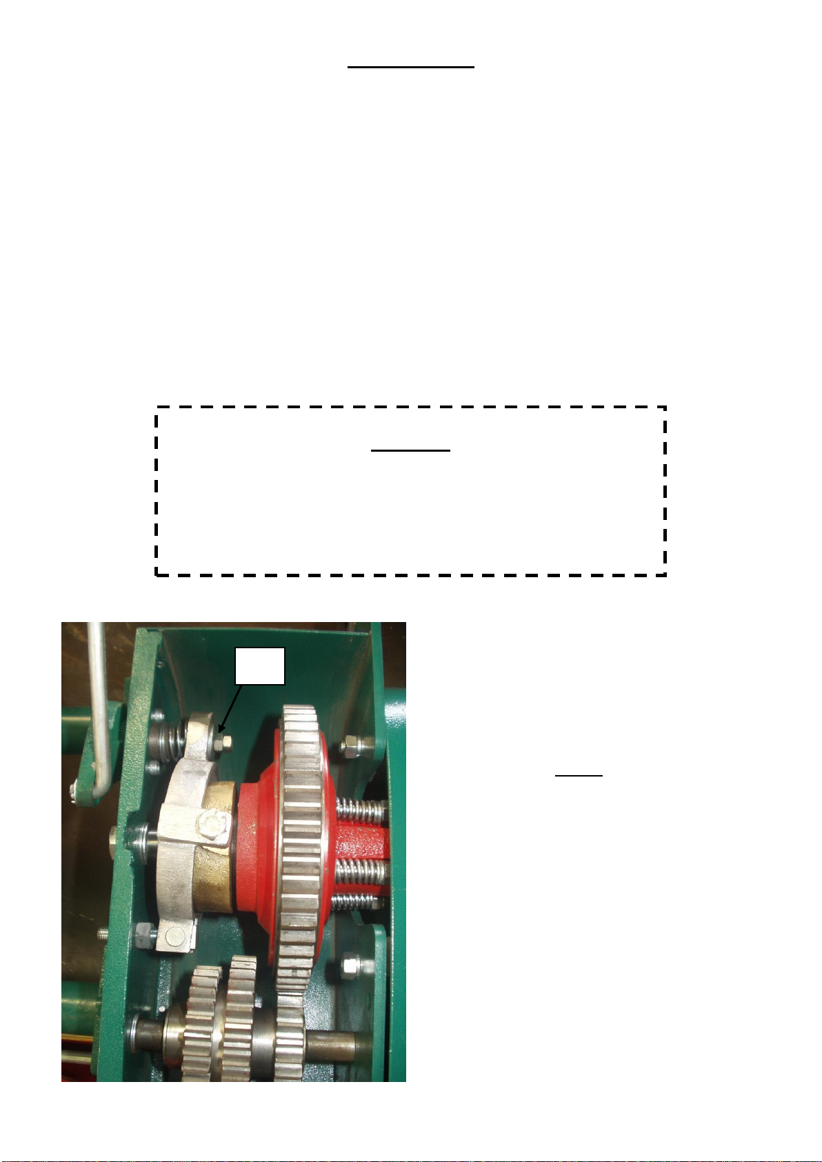
Clutch:
To be certain that the clutch is fully
engaged without the possibility of
slippage, there should be approximately
1½” of free movement (at the clutch
operating lever knob) before the
resistance of clutch operation is felt. This
adjustment is made by means of the self-
locking nut “E”
E
5
Chains:
Adjustment: Loosen chain adjuster locking bolt (14) and slide the chain adjuster in the desired
direction. A chain should ever be adjusted too tightly. It is advisable to leave the cutter chain with
a little slackness so that slight adjustment of the cutter can be made without having to re-adjust this
chain each time.
Grass Deflector:
The grass deflector is adjustable to permit grass to be thrown into the box at the desired angle.
Adjustment: Loosen clamping screws and raise or lower as required.
V Belt Drive:
The V Belt tension is correct when there is about ½” up and down movement of the belt midway
between the pulleys.
Adjustment: To tighten belt, remove motor cover, loosen four nuts holding down the motor, and
force the motor to rear. Then re-tighten nuts.
Note: V Belts are designed to run dry, and under no condition is belt dressing required.
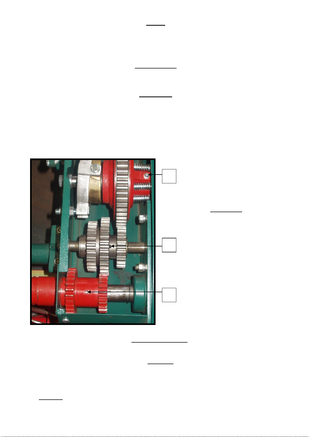
Lubrication:
Pre-lubricated, sealed ball races
are fitted to the cutter; drum shaft,
countershaft and front roller. No
further lubrication is necessary to
theses 8 races. Drums are fitted
with special self-lubricating
bushes and do not require
lubrication.
Driving Chains: grease or
medium oil used sparingly
Gearbox: use medium oil at
points B, C and D. Use grease
sparingly on gear teeth
C
D
B
Front Roller Scraper:
Loosen clamping bolts on each end, adjust scraper to just clear the roller and re-tighten clamps.
Cleaning:
This mower is constructed of first class materials and will give longer and more efficient service if
kept clean. After cutting and before putting machine away, wipe blade down with an oily rag.
Occasionally check nuts and bolts for tightness. Do not water the machine down.
Warning: State Electricity Authority regulations provide that it is always necessary to disconnect
the power supply before effecting and adjustments to the machine.
6
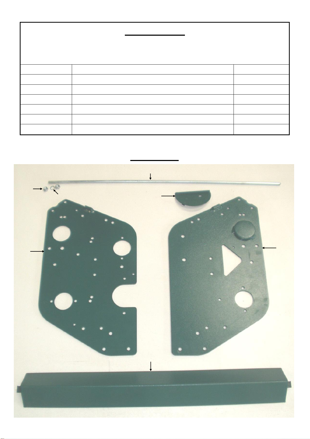
SECTION 1
REFER FIGURE 1
ILLUS. NO.
DESCRIPTION
PART NO.
1
LH SIDE FRAME
305795
2
RH SIDE FRAME
305779
3
SCRAPER TROUGH
305664
4
TROUGH COVER PLATE
305728
5
TROUGH PIVOT BAR
305701
6
M10 SPRING WASHER
STANDARD
7
M10 NUT
STANDARD
2
3
6
7
4
5
1
FIGURE 1
7
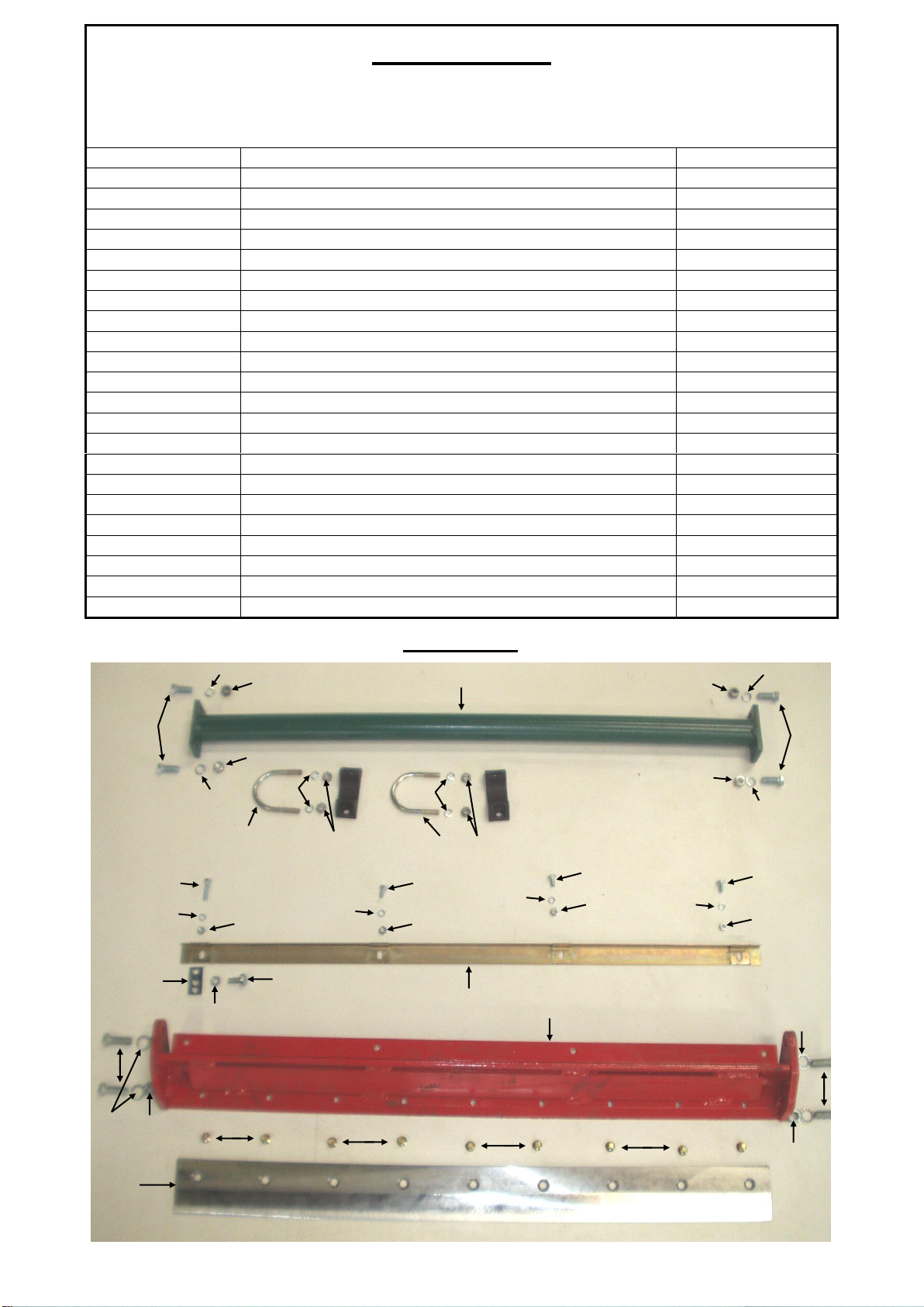
SECTION 2
REFER FIGURE 2
ILLUS. NO.
DESCRIPTION
PART NO.
1
MAINSTAY TUBE
301428
2
HOUSING SIDE SEAT BLOCK
302076
3
3/8" UNF x 1 1/4" SET SCREW
STANDARD
4
3/8" UNF x 1" SET SCREW
STANDARD
5
M10 SPRING WASHER
STANDARD
6
3/8" UNF NUT
STANDARD
7
SEAT BLOCK CLAMP
302084
8
M8 SPRING WASHER
STANDARD
9
M8 NUT
STANDARD
10
DEFLECTOR STRIP
301065
11
M6x12 SET SCREW
STANDARD
12
M6 SPRING WASHER
STANDARD
13
SOLE PLATE
301735
14
TROUGH SUPPORT
305752
15
M8x20 PAN HEAD SCREW
STANDARD
16
M8 HALF-NUT
STANDARD
17
BOTTOM BLADE
393000
18
BOTTOM BLADE SCREW (9 off)
2071924
19
7/16" UNF x 1 1/4" SET SCREW
STANDARD
20
7/16" UNF NUT
STANDARD
21
M12 SPRING WASHER
STANDARD
22
M6x16 SET SCREW
STANDARD
23
M6 NUT
STANDARD
1
2
2
FIGURE 2
3
4
5
5
5
5
6
6
6
6
7
7
8
8
9
9
10
11
11
11
12
12
12
12
13
14
15
16
17
18
18
18
18
19
19
20
20
21
21
22
23
23
23
23

FIGURE 3
8
1
2
2
4
3
5
6
6
7
7
3
8
8
9
9
9
9
9
9
10
10
10
10
10
11
12
12
12
12
12
12
13
13
13
10
13
14
15
16
17
18
18
19
19
20
21
21
22
23
23
24
25
25
26
27
28
28
29
29
30
30
31
31
32
32
33
34
34
35
36
36
37
37
38
38
39
40
48
41
41
42
43
43
44
44
45
46
47
47
48
49
49
50
50
21
40

ILLUS. NO DESCRIPTION PART NO
1 FRONT ROLLER 301516
2 BEARING SEAL WASHER 301057
3 6203 FRONT ROLLER BEARING 1122327
4 LH FRONT ROLLER BRACKET 301030
5 RH FRONT ROLLER BRACKET 301049
6 FRONT ROLLER ADJUSTER ROD 301559
7 ADJUSTER ROD RETAINER CLIP 2501036
8 ADJUSTER ROD PURCHASE BLOCK 301583
9 5/16" UNF NUT STANDARD
10 3/8" UNF NUT STANDARD
11 TOP SPACER BAR 305630
12 M10 FLAT WASHER STANDARD
13 M10 SPRING WASHER STANDARD
14 FRONT ROLLER SCRAPER BAR 305920
15 FRONT ROLLER SCRAPER BLOCK 305802
16 M5x16 CHEESE HEAD SCREW STANDARD
17 M5 STAR WASHER + M5 NUT STANDARD
18 3/16"x5/8" SELLOCK PIN 2211047
19 SCRAPER BOLT 303503
20 FRONT ROLLER SCRAPER STRIP 305920.3
21 M10 NUT STANDARD
22 16 BLADED CUTTING CYLINDER 305074
23 CUTTING CYLINDER WASHER 163432
24 TEASING BRUSH BAR 304488
25 6304 CUTTER BEARING 1123423
26 RH CUTTER BEARING HOUSING 301647
27 LH CUTTER BEARING HOUSING 301698
28 5/16" BSW x 3" SET SCREW STANDARD
29 CUTTER BEARING HOUSING SPACER 301680
30 BEARING HOUSING PIVOT BOLT 163440
31 M12 STAR WASHER STANDARD
32 1/2" UNF NUT STANDARD
33 LH LOCKNUT 161277
34 M10x30 SUP SQUARE BOLT STANDARD
35 M8x25 GRUB SCREW STANDARD
36 CUTTER ADJUSTER SCREW STANDARD
37 CUTTER ADJUSTER SCREW PURCHASE BLOCK 301727
38 TEASING BRUSH MOUNTING BRACKET 303423
39 CUTTER SPROCKET 165340
40 M10x40 CUP SQUARE BOLT + M10 FLAT WASHER + M10 NYLOC NUT STANDARD
41 3/8" UNF x 1" SET SCREW STANDARD
42 TEASING BRUSH 304486
43 HEIGHT ADJUSTER STUD 303407
44 MOUNTING BRACKET SUPPORT PLATE 303431
45 M6x35 COUNTER SUNK SCREW STANDARD
46 M6 SPRING WASHER + M6 NUT STANDARD
47 M4x10 BRONZE DRIVE PIN STANDARD
48 M8x20 SET SCREW + M8 SPRING WASHER + M8x22 FLAT WASHER STANDARD
49 1/4" UNF NUT STANDARD
50 M10x25 SET SCREW STANDARD
9
REFER FIG. 3

FIGURE 4
10
1
2
2
1
4
4
4
4
7
7
13
12
11
6
6
6
6
3
3
3
20
29
9
9
9
30
30
29
5
13
12
10
21
8
15
14
17
18
19
19
16
34
31
32
26
19
23
14
35
26
24
25
36
28
17
18
18
19
22
22
21
18
26
27
33
37
37
19

ILLUS. NO DESCRIPTION PART NO
1 OUTER DRUM 303992
2 INNER DRUM 304012
3 DRUM BUSH 1771189
4 RATCHET BOX 301188
5 DRUM PAWLS 333024
6 1/4" BSW x 5/8" RATCHET BOX SET SCREW STANDARD
7 DRUM SHAFT SLEEVE 301808
8 DRUM SHAFT 301217
9 WOODRUFF KEY NO.9 3802267
10 LH DRUM SHAFT COLLAR 301840
11 RH DRUM SHAFT COLLAR 301858
12 3/8" BSW x 1" GRUB SCREW STANDARD
13 3/8" BSW NUT STANDARD
14 6204 DRUM SHAFT BEARING 1122422
15 48mm INTERNAL CIRCLIP 1502480
16 LH DRUM BEARING HOUSING 301815
17 5/16" UNF x 3/4" SET SCREW STANDARD
18 M8 SPRING WASHER STANDARD
19 5/16" UNF NUT STANDARD
20 30T DRUM SPROCKET 301866
21 1/2" UNF NUT STANDARD
22 5/8" FLAT WASHER 143271
23 RH DRUM BEARING HOUSING 301823
24 DRUM ADJUSTING SCREW 304434
25 DRUM ADJUSTING SCREW PURCHASE BLOCK 301583
26 3/8" UNF NUT STANDARD
27 M10 SPRING WASHER STANDARD
28 ADJUSTING SCREW PIVOT SLEEVE 304469
29 PAWL RETAINER 301196
30 5/16" BSW x 3/4" HARDENED SQUARE HEAD SCREW 3162306
31 CHAIN ADJUSTER 161453
32 CHAIN ADJUSTER BOLT 161461
33 M10 FLAT WASHER STANDARD
34 CLUTCH TO DRUM CHAIN 2986543
35 5/16" BSW x 3/4" SET SCREW STANDARD
36 BEARING SEAL CUP 301831
37 M8x22 FLAT WASHER STANDARD
11
REFER FIG. 4
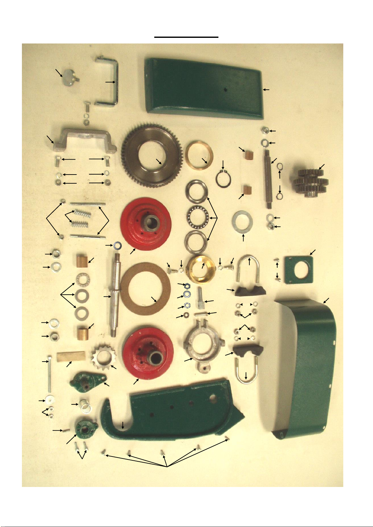
FIGURE 5
12
1
2
3
4
6
5
7
8
8
8
8
9
8
10
11
12
14
15
15
16
16
18
19
20
21
22
23
23
24
24
25
26
27
28
28
29
30
31
31
32
33
34
35
36
37
38
39
40
40
41
42
43
44
45
46
47
48
49
13
17
17
50
51
52
53
53
54
55
56
56

ILLUS. NO DESCRIPTION PART NO
1 CLUTCH HOUSING SIDE 302068
2 CLUTCH HOUSING BODY 302092
3 M5x10 CHEESE HEAD SCREW STANDARD
4 CLUTCH RAMP - MOVABLE 305509
5 M6x80 SET SCREW STANDARD
6 M6x20 FLAT WASHER STANDARD
7 M6 NUT STANDARD
8 M8 SPRING WASHER STANDARD
9 5/16" UNF NUT STANDARD
10 CLUTCH RAMP - FIXED 302340
11 CLUTCH RAMP STOP 302359
12 M5x12 CAP SCREW STANDARD
13 HOUSING COVER SCREW 302164
14 CLUTCH RAMP SPRING 302375
15 SEAT BLOCK CLAMP 302084
16 SEAT BLOCK 302076
17 7/16" UNF NUT STANDARD
18 M8 NUT STANDARD
19 52T DRUM CLUTCH GEAR 302252
20 DRUM CLUTCH GEAR BUSH 172216
21 DRUM CLUTCH SHAFT 302279
22 INNER THRUST BEARING 3531020
23 M12 FLAT WASHER STANDARD
24 1/2" UNF NUT STANDARD
25 CLUTCH RELEASE YOKE 302308
26 CLUTCH YOKE PILLAR 302316
27 M10 FLAT WASHER STANDARD
28 3/8" UNF NUT STANDARD
29 YOKE PIN 302332
30 YOKE PIN RETAINER CLIP 2501036
31 TRUNNION PIVOT SCREW 302324
32 CLUTCH PLATE - STUD SIDE 301286
33 CLUTCH SPRING STUD 302236
34 CLUTCH SPRING 302244
35 CLUTCH RELEASE TRUNNION 302287
36 CLUTCH PLATE LINING 301276
37 1/4" UNF NYLOC NUT STANDARD
38 M5x10 CHEESE HEAD SCREW STANDARD
39 CLUTCH PLATE - SPROCKET SIDE 301252
40 CLUTCH PLATE BUSH 3111271
41 14T DRUM CLUTCH SPROCKET 302228
42 CLUTCH SHAFT SHIM WASHER 302279.1
43 OUTER THRUST BEARING 3531026
44 RELEASE THRUST WASHER 302295
45 40mm EXTERNAL CIRCLIP 1501079
46 FELT OIL STRIP 302210
47 CLUTCH HOUSING COVER 302130
48 CLUTCH SHAFT SUPPORT BRACKET 302121
49 5/16" UNF x 1" SET SCREW STANDARD
50 CLUTCH HOUSING SIDE COVER 302201
51 CLUTCH COVER BRACKET 302172
52 INTERMEDIATE CLUSTER GEAR 302412
53 INTERMEDIATE CLUSTER GEAR BUSH 3111030
54 5/8" EXTERNAL CIRCLIP 1501020
55 INTERMEDIATE GEAR SHAFT 302420
56 M11 FLAT WASHER STANDARD
13
REFER FIG. 5

FIGURE 6
14
1
2
3
4
5
6
7
8
10
9
11
12
13
14
15
16
17
18
19
20
23
22
24
25
26
21
27
28
29
30
31
32
32
34
33
33
35
35
36
36
37
38

ILLUS. NO DESCRIPTION PART NO
1 COUNTER SHAFT 302875
2 6204 COUNTER SHAFT BEARING 1122422
3 LH COUNTER SHAFT BEARING HOUSING 301815
4 UCFL204 FLANGE BEARING 301825
5 40mm INTERNAL CIRCLIP 1502012
6 M12x35 SET SCREW STANDARD
7 M12 NYLOC NUT STANDARD
8 5/16" UNF x 1" SET SCREW STANDARD
9 5/16" UNF NUT STANDARD
10 M8 SPRING WASHER STANDARD
11 COUNTER SHAFT PULLEY 301954.1
12 8mm WOODRUFF KEY 3802750
13 M10x30 GRUBSCREW (INCLUDED WITH TAPER LOCK) STANDARD
14 TAPER LOCK 301954.2
15 5/8" UNF NUT STANDARD
16 17T COUNTER SHAFT SPROCKET 301962
17 WOODRUFF KEY NO.9 3802267
18 COUNTER SHAFT GEAR 302383
19 1/4" LOCATING BALL 3421166
20 LOCATING SPRING 302391
21 25mm EXTERNAL CIRCLIP 1501052
22 "O" RING 150652
23 CHAIN ADJUSTER 161453
24 CHAIN ADJUSTER BOLT 161461
25 M10 FLAT WASHER STANDARD
26 3/8" UNF NUT STANDARD
27 CHAIN - COUNTER SHAFT TO CUTTING CYLINDER 2986519
28 COUNTER SHAFT GEAR KEY 302402
29 CLUTCH HOUSING SIDE COVER 302201
30 COUNTER SHAFT COVER 302093
31 M5x10 CHEESE HEAD SCREW STANDARD
32 COUNTER SHAFT COVER "P" CLIP STANDARD
33 M5x15 CHEESE HEAD SCREW STANDARD
34 M5 NUT STANDARD
35 M5 STAR WASHER STANDARD
36 M5 FLAT WASHER STANDARD
37 M10 SPRING WASHER STANDARD
38 5/8" FLAT WASHER 143271
15
REFER FIG. 6
FIGURE 7
16
1
2
2
3
3
4
4
5
6
7
8
8
9
10
10
11
12
13
14
14
14
15
16
16
17
17
Other manuals for BG 760
2
Table of contents
Other PROTEA Lawn Mower manuals


Popular Lawn Mower manuals by other brands

Cub Cadet Commercial
Cub Cadet Commercial S6031 Tank S Operator's manual

Craftsman
Craftsman 247.27022 owner's manual

Toro
Toro 14-38Z TimeCutter Operator's manual

Craftsman
Craftsman 917.255980 owner's manual

Poulan Pro
Poulan Pro XT22H48YT Operator's manual

Maxim
Maxim 2035BVB Operator's manual and parts list


