Instructions for Assembling
Un©rafing
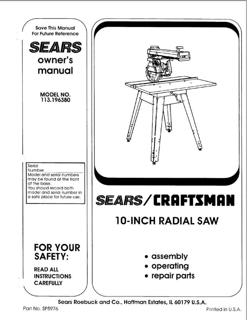
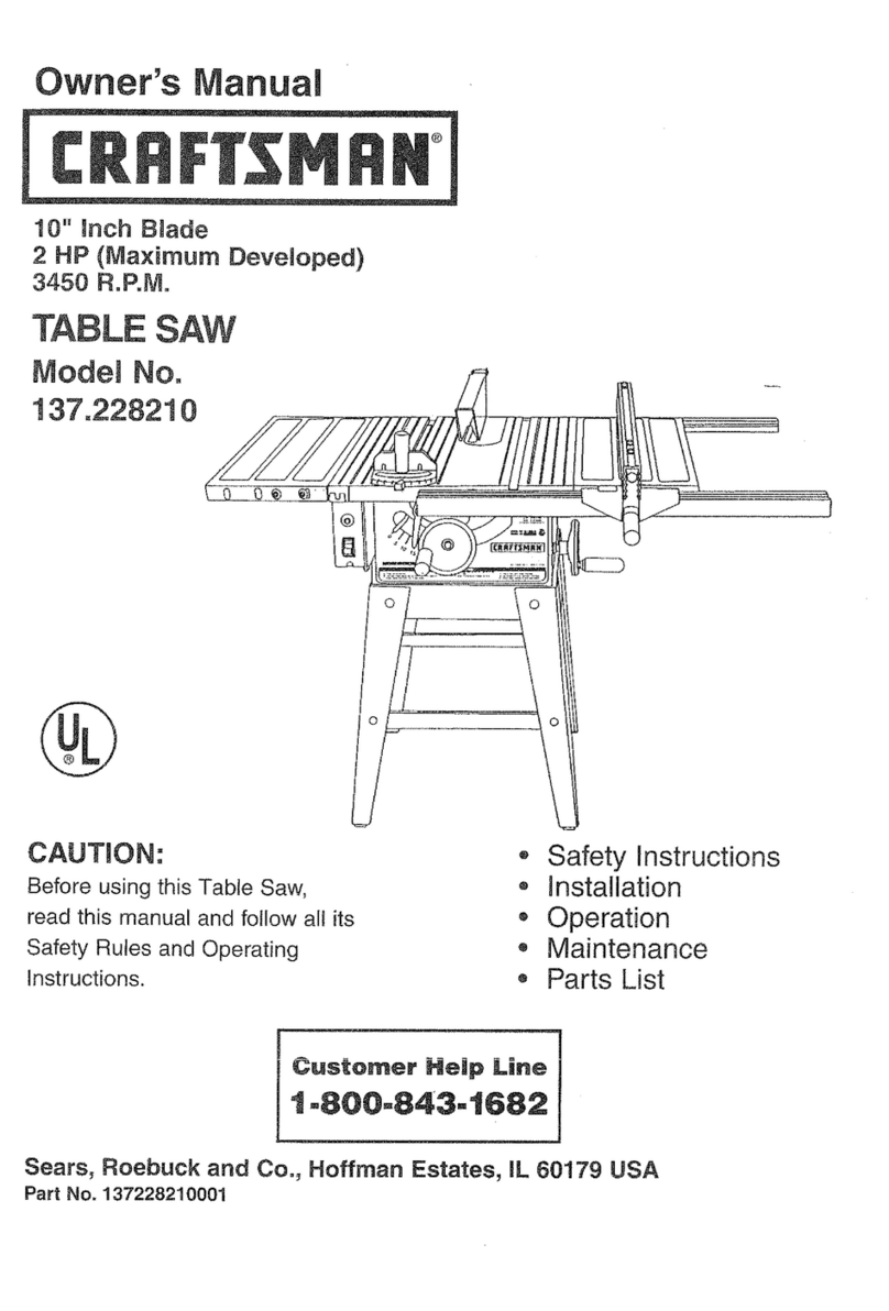
Your C_man Bu_der's Saw is shipped complete
(less motor) in one crate, with a carton for miscellaneous
parts inside the crate. Remove nails around sides 'at
bottom d crate. The top and sldes can then be lihed
off. Remove bol_ in legs from bottom of the crate
and lift saw off. h_tructlous for removing are also
printed on the crate. The carton between the legs cou-
talns the rip fence, lah-hand miter, right-hand miter,
saw guard_ splitter, dust bag, switch, pulleys and bdu,
and an envdope with the necessary small parts such as
nu_, etc., needed for assembly.
Assembly
Your Builder's Saw has been assembled, operated,
and inspected at the factory. The saw carriage has been
fastened securely for shipment. There is a pin attached
with a chain to the leh-hand side dthe carriage that
locks the carriage for ripping and dado purpeees at
three points. The carriage Is now locked and fastened.
Open side door removing pin and fastening, so car-
riage can be moved. Mount your motor on the motor
support plate with the motor shah and saw spindle
lined up so that the saw is turning TOWARD the
operator. We have supplied slots in the motor support
plate that will accommodate the holes in most motor
bases. However if they do not fit your motor base,
use the ones that do agree and drill any others that
are necessary° For efficient operation use a 3450 R.PoM.
motor of not less than _ HiP. Any difference in the_
R.P.M. of your motor can be taken care of by usingr
different slz_ of pulleys in accordance with the fol-
lowing table:
Saw Spin_© Motor Motor Appl_ox.
Dia. PuUcy PuUcy R.P,M. Spin.g.P.M.
82V2 3gz 3450 48O0
8 2½ 6_ 1750 48O0
10 2V2 3 3450 4200
I0 2_/2 6 1750 42O0
-- --- 7
SRW
Travel
17Y2
17Yz
15½
15½
2¼
2¼
3¼
3¼
Motor should have a _/_-inch shaft with a 3/16-inch key-
way. After mounting the motor, fasten the 3-inch or
doublesheavepulleyson themotor shaftand puton the
two brits.Ifthebritsfurnishedarenotthe fightlength
you can probablyget the lengthyou need at your
nearest Sears Retail or Mail Order Store. Length of
belt is determined by measuring over the OUTSIDE
diameter of the pulley after iustallation. An adjustment
for tightening brits will be found at the rear of the
motor support plate. Do not have the balls too tight.
The switch is mounted withtwo screws to the front
panel. The following data should be followed for de.
retraining the size of wire recommended for the proper
operation d motor:
MOTOR
H.P.
1
1
1½
MOTOR
VOLTAGE
115
230
115
230
115
230
D]STANCE FROM OUTLET
TO MOTOR
50-feet
No. 14
No. 14
No. 14
No. 14
No. 12.
No. 14
100-f_ 150-feet
No. 12 No. 10
No, 14, No. 14
No. I0 No. 8
No. 14 No. 12
No. 8 No. 6
No. 14 No. 12
and Operatin8 Your Saw
Bolt the splitter angle bracket part No. 7027 to the rear
of the dust chute. Drop the splitter blade, with handl_
over the saw, through the saw slot in the top of the
table. Bolt it with the splitter retaining plate part No.
7125 to the angle bracket part No. 7027. The splitter
blade must be directly in llne with the saw blade. Bolt
guard to the spliRerblade.
The six-inch hand wheel at the front will raise and
lowerthe entire assembly, consisting of saw blade, split°
ter, guard, and handle, to the required height above the
table. The guard should not be more than _ inch
above the work passing _gh saw blade.
The fence guide bar part No. 7121 should be checked
to be sure it has not ja_ed out of llne in shipment. If
so,line up paralidwiththe tabletop and tightenthe
sk mounting screws. For attaching the rip _ence to the
table top, pull out on the small pinion gear knob No.
7235, and slide the fence overthe gmda bar. The fence
may now be moved back and forth by hand. For fin_
adjus_nent engage the piniongear with fence guide bar
by pushing in the knob. The fence can be locked _ront
and back by pushing down on lever No. 7239. If clamp-
ing action is not as tight as desired it may be adjusted
by the jam nuts on the rear end of the tie rod that
runs through the complete fence.
Cumin9 Capa¢i
The depth of cut is controlled by raising and lower-
ing the saw blade using the hand wheel located on
the front panel. The saw can be set to cut thicknesses
from "0" to 3¼ inches. The maximum saw carriage
t_avd is 15_ inches.
Lubrication
Greesin_
The spindle bearings are lubricated at the [ac_
and will' give you approximately 1000 hours of use be-
fore they need to be lubricated. In the housing
the spindlebearings there is a Zerk type fitting which
may be reached from the lab-hand door. Use a ha_
type grease gun, with any high-pressure chassis gun
grease. Do not PACK bearings.
Oi|in_
The followlng parts should be oiled frequently with
No. 20 or No. 30 _utomobile engine oil:
1. Saw raising screw and _,
2. The miter gear sha_ part No. 7063.
3. The hexagon sha_ part No. 7045.
4. Oil poin_ where there is f_ic_io_
between two ormore moving sm_ces
or when a slipfitisnec_sary such
as where the fence _lidas, etc.
To preventsaw table and saw from _th_g, keep
them covered with a film of oll when not in we a_
wipe off before using.
5

