8
D-3.3) Pump-Down Test:
After the pump has been properly wired and lowered into the
basin, sump or lift station, it is advisable to check the system
by filling with liquid and allowing the pump to operate through
its pumping cycle. The time needed to empty the system, or
pump-down time along with the volume of water, should be
recorded on the start-up report.
SECTION E: PREVENTATIVE MAINTENANCE
As the motor is oil filled, no lubrication or other maintenance
is required, and generally Barnes Pumps will give very
reliable service and can be expected to operate for years on
normal sewage pumping without failing. However as with any
mechanical piece of equipment a preventive maintenance
program is recommended and suggested to include the
following checks:
1) Inspect motor chamber for oil level and contamination and
repair as required per section F-1.
2) Inspect impeller and body for excessive build-up or
clogging and repair as required per section F-2.
3) Inspect motor, bearings and shaft seal for wear or leakage,
replace as required per section F-3.
SECTION F: SERVICE AND REPAIR
NOTE: All item numbers in ( ) refer to Figures 9 & 10,
3450RPM and Figures 11 & 12 , 1750RPM.
F-1) Lubrication:
Anytime the pump is removed from operation the cooling oil
in the motor housing (2) must be checked visually for oil level
and contamination.
F-1.1) Checking Oil:
Motor Housing - To check oil, set unit upright. Remove cap
screws (6) and lockwashers (4), lift conduit box assembly (10)
from motor housing (2) but DO NOT disconnect conduit box
wiring from motor leads. With a flashlight, visually inspect the
oil in the motor housing (2) to make sure it is clean, clear and
that oil level is above all internal componentry.
F-1.2) Testing Oil:
1. Place pump on it’s side, remove cap screws (6) and
lockwashers (4), lift conduit box assembly (10) from motor
housing (2) and drain oil into a clean, dry container.
2. Check oil for contamination using an oil tester with a range
to 30 Kilovolts breakdown.
3. If oil is found to be clean and uncontaminated (measure
above 15 KV. breakdown), refill the motor housing as per
section F-1.3.
4. If oil is found to be dirty or contaminated (or measures
below 15 KV. breakdown), the the pump must be carefully
inspected for leaks at the shaft seal (46), conduit box
assembly (10), O-rings (11) and (42) pipe plug (5) before
refilling with oil. To locate the leak, perform a pressure
test as per section F-1.4. After leak is repaired, refill with
new oil as per section F-1.3.
F-1.3) Replacing Oil:
Motor Housing - Drain all oil from motor housing and dispose
of properly. Refill with (see parts list for amount) new cooling
oil as per Table 1. An air space must remain in the top of
the motor housing to compensate for oil expansion (see
Fig. 9 or 11). Set unit upright and fill only until the motor,
as viewed through the conduit box opening, is just covered
and no more. Reassemble the O-ring (11), conduit box
assembly (10), cap screws (6) and lockwashers (4), apply
thread locking compound to each cap screw (6) thread before
installing. Torque cap screws (6) to 15 ft, lb.
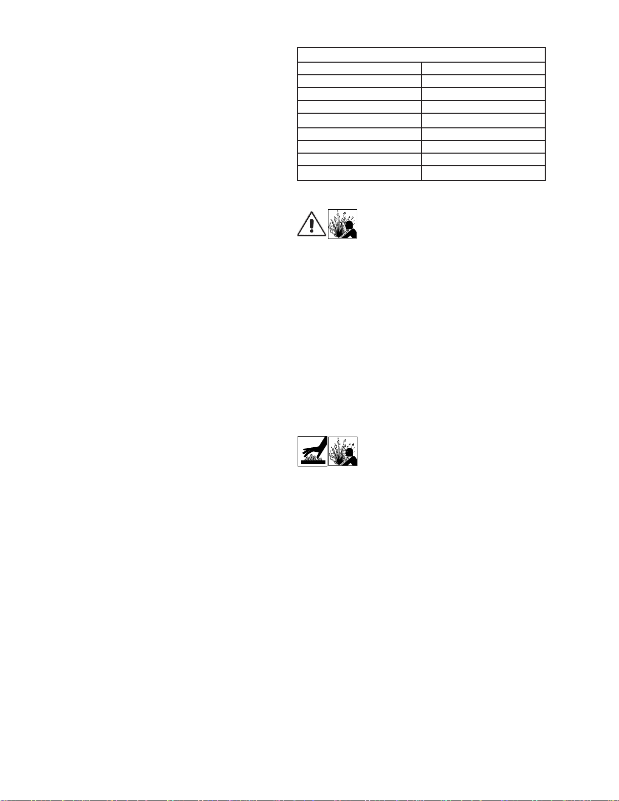
TABLE 1 - COOLING OIL - Dielectric
SUPPLIER GRADE
BP Enerpar SE100
Conoco Pale Paraffin 22
Mobile D.T.E. Oil Light
G & G Oil Circulating 22
Imperial Oil Voltesso-35
Shell Canada Transformer-10
Texaco Diala-Oil-AX
Woco Premium 100
Important! - Do not overfill oil. Overfilling
of motor housing with oil can create
excessive and dangerous hydraulic
pressure which can destroy the pump
and create a hazard. Overfilling oil voids
warranty.
F-1.4) Pressure Test:
Motor Housing - Before checking the pump for leaks around
the shaft seal, o-rings, and cord inlet, the oil level should be
full as described in section F-1.3. Remove pipe plug (5) and
lifting handle (7) from motor housing (2). Apply pipe sealant
to pressure gauge assembly and tighten into pipe plug hole
(see Figure 2). Pressurize motor housing to 10 P.S.I. Use a
soap solution around the sealed areas and inspect joints for
“air bubbles”. If, after five minutes, the pressure is still holding
constant, and no “bubbles” are observed, slowly bleed the
pressure and remove the gauge assembly. Replace the pipe
plug using a sealant. If the pressure does not hold, then the
leak must be located.
Caution! - Pressure builds up extremely
fast, increase pressure by “tapping” air
nozzle. Too much pressure will damage
seal. Do Not exceed 10 P.S.I. in motor
housing.
F-2) Impeller and Volute Service:
F-2.1) Disassembly and Inspection:
To clean out volute (26), disconnect power, remove hex
nuts (20) and lockwashers (19), vertically lift motor and seal
assembly from volute (26). Clean out body if necessary.
Clean and examine impeller (28) for pitting or wear, replace
if required. Inspect square ring (42) and replace if cut or
damaged. If impeller (28) requires replacing, remove jam
nut (34) and washer (35), by placing a flat screwdriver in the
slot of the end of the shaft to hold the shaft stationary while
unscrewing the impeller (28). Once impeller (28) is removed,
remove pull washer (16) and exclusion seal (17) if damaged
or cut.
F-2.2) Reassembly:
Position exclusion seal (17) on shaft until it seats against the
stationary portion of seal (46). Place pull washer (16) on shaft
until it seats against exclusion seal (17). To install impeller
(28), clean the threads with loctite cleaner and screw impeller
(28) onto the shaft hand tight. Apply thread locking compound
to shaft threads and install washer (35) and jam nut (34).
Torque to 40 ft. lbs. Rotate impeller to check for binding.
Position o-ring (42) on volute flange and position impeller
and motor housing assembly over studs and onto volute (26).