Crary CYCLONE 4400 User manual

RECORD SERIAL NUMBER HERE
Manual PN 24076
Rev. 100813
OWNER'S/PARTS
MANUAL
JOHN DEERE

DISCLAIMER
This document is based on information available at the time of its publication. While efforts have been made to be ac-
curate, the information contained herein does not purport to cover all details or variations, nor to provide for every pos-
sible contingency in connection with installation, operation, or maintenance. Features may be described herein which
are not present in all systems. Crary Industries assumes no obligation of notice to holders of this document with respect
to changes subsequently made.
Crary Industries assumes no responsibility for the accuracy, completeness, sufficiency, or usefulness of the information contained
herein.
SPECIFICATIONS AND DESIGN ARE SUBJECT TO CHANGE WITHOUT NOTICE.
Crary Industries is continually making improvements and developing new equipment. In doing so, we reserve the right
to make changes or add improvements to our product without obligation for equipment previously sold.
Becausemodificationtothesesystemsmayaffecttheperformance,function,andsafetyofitsoperation,nomodifications
are to be made without the written permission of Crary Industries. Part replacements should be with original equipment
supplied by Crary Industries.
THE CRARY INDUSTRIES STATEMENT OF PRODUCT SAFETY
As a manufacturer of specialized agricultural equipment, Crary Industries fully recognizes its responsibility of providing
its customers products that perform their expected use in a reasonably safe manner. Safety considerations shall be an
integral and high priority part of all engineering/design analysis and judgments involving Crary products. It is our stated
policy that our products will be manufactured to comply with the safety standards specified by the American Society of
Agricultural Engineers, the National Electrical Code, the Society of Automotive Engineers, and/or any other applicable
recognized standards at the time manufactured. However, this statement should not be construed to mean that our
product will safeguard against a customer’s own carelessness or neglect in violating common safety practices specified
in each product’s manual, nor will we be liable for any such act.
SERIAL NUMBER LOCATION
Always give your authorized Crary dealer the serial
number of your machine when ordering parts, requesting
service,oranyotherinformation.Theserialnumberdecal
is located on the motor mount weldment.
Please record the serial number in the space provided on
the front cover and on the warranty and registration card.
MANUFACTURED BY CRARY INDUSTRIES
MANUFACTURED IN U.S.A.
XXXXXX
WEST FARGO, NORTH DAKOTA 58078 U.S.A.
SERIAL NUMBER
Serial Number Location
HOW TO REACH US
ADDRESS HOURS TELEPHONE
FAX NUMBER E-MAIL
INTERNET
Crary Industries, Inc.
237 12th St. NW
West Fargo, ND 58078
Monday-Friday
8 am-5pm (CST)
For Parts and Service:
Ph: 701.282.5520 •
800.247.7335
Fax: 701.282.9522
Email: service@crary.com •
sales@crary.com
Online: www.crary.com

NOTE
The warranty will not cover gearboxes that have been disas-
sembled within the warranty period.
LIMITED WARRANTY
This warranty applies to all AG and Marine Equipment manufactured by Crary Industries.
Crary Industries warrants to the original owner each new Crary Industries product to be free from defects in material
and workmanship, under normal use and service. The warranty shall extend as shown below from date of delivery. The
product is warranted to the original owner as evidenced by a completed warranty registration on file at Crary Industries.
THE WARRANTY REGISTRATION MUST BE COMPLETED AND RETURNED TO CRARY INDUSTRIES WITHIN 10
DAYS OF DELIVERY OF THE PRODUCT TO THE ORIGINAL OWNER OR THE WARRANTY WILL BE VOID.
Intheeventofa failure, returnthe product, atyour cost, alongwith proof ofpurchase to theselling Crary Industriesdealer.
Crary Industries will, at its option, repair or replace any parts found to be defective in material or workmanship. Warranty
on any repairs will not extend beyond the product warranty. Repair or attempted repair by anyone other than a Crary
Industries dealer as well as subsequent failure or damage that may occur as a result of that work will not be paid under
this warranty. Crary Industries does not warrant replacement components not manufactured or sold by Crary Industries.
1. This warranty applies only to parts or components that are defective in material or workmanship.
2. Thiswarranty doesnot cover normalwear itemsincluding but not limited tobearings, belts, pulleys and reeltines.
3. This warranty does not cover normal maintenance, service or adjustments.
4. This warranty does not cover depreciation or damage due to misuse, negligence, accident or improper main-
tenance.
5. This warranty does not cover damage due to improper setup, installation or adjustment.
6. This warranty does not cover damage due to unauthorized modifications of the product.
CraryIndustries isnot liablefor anyproperty damage,personal injuryor deathresulting fromthe unauthorizedmodification
or alteration of a Crary product or from the owner’s failure to assemble, install, maintain or operate the product in
accordance with the provisions of the Owner’s manual.
Crary Industries is not liable for indirect, incidental or consequential damages or injuries including but not limited to loss
of crops, loss of profits, rental of substitute equipment or other commercial loss.
This warranty gives you specific legal rights. You may have other rights that may vary from area to area.
Crary Industries makes no warranties, representations or promises, expressed or implied as to the performance of its
productsother than those set forth in this warranty. Neitherthe dealer nor any otherperson has anyauthority to makeany
representations, warranties or promises on behalf of Crary Industries or to modify the terms or limitations of this warranty
in any way. Crary Industries, at its discretion, may periodically offer limited, written enhancements to this warranty.
CRARY INDUSTRIES RESERVES THE RIGHT TO CHANGE THE DESIGN AND/OR SPECIFICATIONS OF ITS
PRODUCTS AT ANY TIME WITHOUT OBLIGATION TO PREVIOUS PURCHASERS OF ITS PRODUCTS.
Product Warranty Length
Finger Air Reel 2 year
Crary Wind System 2 year
Big Top 1 year
Top OffAuger 1 year
Cyclone 1 year
Cutting Systems 1 year
WeedRoller 1 year (commercial)
2 year (homeowner)
Replacement Parts 90 days (unless superceded by warranty)
OEM Fans 1 year

TABLE OF CONTENTS
INTRODUCTION...................................................................................................1
SAFETY ................................................................................................................2
2.1 SAFETY ALERT SYMBOL .......................................................................................................................2
2.2 GENERAL SAFETY..................................................................................................................................3
2.3 OPERATING SAFETY..............................................................................................................................4
2.4 MAINTENANCE SAFETY ........................................................................................................................4
2.5 HYDRAULIC SAFETY..............................................................................................................................4
2.6 STORAGE SAFETY.................................................................................................................................4
2.7 ASSEMBLY SAFETY................................................................................................................................4
2.8 SIGN-OFF FORM.....................................................................................................................................5
2.9 SAFETY DECALS.....................................................................................................................................6
AXLE MOUNT FRAME INSTALLATION..............................................................7
3.1 STANDARD AXLE COMBINES.................................................................................................................7
3.2 HEAVY DUTY AXLE..................................................................................................................................7
3.3 9500 SIDEHILL..........................................................................................................................................8
3.4 9400, 9500, 9600.......................................................................................................................................8
BASIC ASSEMBLY...............................................................................................9
4.1 ADJUSTMENT TUBE INSTALLATION......................................................................................................9
4.2 MOTOR MOUNT INSTALLATION.............................................................................................................9
4.3 INSTALL FRONT SHIELD MOUNTING BRACKET (BOTH MODELS)...................................................11
4.4 SHIELD MOUNTING: SINGLE SPINNER MODELS...............................................................................12
4.5 SHIELD MOUNTING: DOUBLE SPINNER MODELS.............................................................................13
4.6 SPINNER DISC MOUNTING: SINGLE SPINNER..................................................................................14
4.7 SPINNER DISC MOUNTING AND TILTING: DOUBLE SPINNER..........................................................15
4.8 MOUNTING REAR SHIELD: SINGLE SPINNER....................................................................................16
4.9 MOUNTING REAR SHIELD: DOUBLE SPINNER..................................................................................17
HYDRAULIC INSTALLATION .............................................................................18
5.1 MODELS 4400, 4420, 6600, 6620, 7700 & 8820....................................................................................18
5.2 MODELS: 9000S.....................................................................................................................................20
5.3 PULL TYPE MODELS 7701 & 7721........................................................................................................22
PAN ASSEMBLY.................................................................................................24
6.1 4400 MODELS ........................................................................................................................................24
6.2 6600, 6620, 7700, 7720 MODELS ..........................................................................................................25
6.3 6620, 7720 & 8820..................................................................................................................................26
6.4 9400, 9500 & 9600..................................................................................................................................26
PARTS.................................................................................................................28
7.1 SINGLE SPINNER CHAFF SPREADER (PN 23388).............................................................................28
7.2 DOUBLE SPINNER CHAFF SPREADER (PN 23389)............................................................................30
7.3 AXLE MOUNT ASSEMBLY PARTS LISTSAND DIAGRAMS.................................................................32
7.4 HYDRAULIC ASSEMBLY PARTS LISTS AND DIAGRAMS....................................................................33
7.5 FLOW PAN KIT ASSEMBLY PARTS LISTS AND DIAGRAMS ...............................................................34
TROUBLESHOOTING........................................................................................38
BOLT TORQUE............................................................................................................40
DESCRIPTION PAGE

1
CYCLONE CHAFF SPREADER - JD
Section INTRODUCTION
1
Congratulationson your choice of a newCyclone Chaff Spreader to complement your farmingoperation.Thisequipment
has been designed and manufactured to meet the needs of a discerning agricultural industry.
Safe, efficient, and trouble free operation of your Cyclone Chaff Spreader requires that you and anyone else who will be
operating or maintaining the machine read and understand the Safety, Operation, Maintenance, and Trouble Shooting
informationcontainedwithintheowner'smanual. Checkeachitemreferredtoand acquaint yourself with the adjustments
required to obtain efficient operation.
This manual covers all models of the Cyclone manufactured by Crary Industries for John Deere equipment. Use the
table of contents as a guide to locate required information.
Keep this manual handy for frequent reference and to pass on to new operators or owners. Call your Crary dealer or
distributor if you need assistance, information, or additional copies of the manuals.
Many people have worked on the design, production, and delivery of this machine. They have built into it the highest
quality of materials and workmanship. The information in this manual is based on the knowledge, study, and experience
of these people through years of manufacturing specialized farming machinery.
The performance of the machine depends on proper maintenance and adjustment. Even if you are an experienced
operator of this or similar equipment, we ask you to read the owner's manual before running the machine. Keep the
manual handy for future reference. It has been carefully prepared, organized, and illustrated to assist you in finding the
informationyou need. Your Crarydealer will behappy to answer anyfurther questions youmay have aboutthe machine.

2CYCLONE CHAFF SPREADER - JD
Section SAFETY
2
This Safety Alert Symbol means:
ATTENTION! BECOME ALERT!
YOUR SAFETY IS INVOLVED!
TheSafetyAlertsymbol identifies important
safetymessagesonthemachineandin the
manual. When you see this symbol, be
alert to the possibility of personal injury or
death. Follow the instructions in the safety
message.
Why is SAFETY important to you?
Accidents Disable and Kill
Accidents Cost
Accidents Can Be Avoided
SIGNAL WORDS:
NotetheuseofthesignalwordsDANGER,WARNING,
CAUTION, IMPORTANT and NOTE with the safety
messages. The appropriate signal word for each mes-
sage has been selected using the following guidelines:
Three Big Reasons
2.1 SAFETY ALERT SYMBOL
WARNING
Indicates a potentially hazardous situation that, if not
avoided, could result in death or serious injury, and
includes hazards that are exposed when guards are
removed. It may also be used to alert against unsafe
practices.
DANGER
Indicates an imminently hazardous situation that, if not
avoided,will result in death orseriousinjury. Thissignal
word is to be limited to the most extreme situations,
typically for machine components that, for functional
purposes, cannot be guarded.
CAUTION
Indicates a potentially hazardous situation that, if not
avoided, may result in minor or moderate injury. It may
also be used to alert against unsafe practices.
IMPORTANT
Instructions that must be followed to ensure proper
installation/operation of equipment.
NOTE
General statements to assist the reader.

3
CYCLONE CHAFF SPREADER - JD
SAFETY
YOU are responsible for the SAFE operation and main-
tenance of your machine. You must ensure that you and
anyone else who is going to operate, maintain or work
around the machine are familiar with the operating and
maintenance procedures and related safety information
contained in this manual. This manual will alert you to
all good safety practices that should be adhered to while
operating the machine.
Remember, YOU are the key to safety. Good safety prac-
tices not only protect you but also the people around you.
Makethese practices aworkingpartof your safetyprogram.
Be certain that EVERYONE operating this equipment is
familiarwiththerecommendedoperatingandmaintenance
procedures and follows all the safety precautions. Most
accidents can be prevented. Do not risk injury or death by
ignoring good safety practices.
• Owners must give operating instructions to opera-
torsoremployeesbeforeallowingthem to operate
the machine, and annually thereafter per OSHA
(Occupational Safety and Health Administration)
regulation 1928.57.
• Themost importantsafetydevice onthisequipment
isasafe operator. Itistheoperator’sresponsibility
to read and understand all Safety and Operating
instructions in the manual and to follow them. All
accidents can be avoided.
• A person who has not read and understood all
operating and safety instructions is not qualified
to operate the machine. An untrained operator
exposes himself and bystanders to possible seri-
ous injury or death.
• Donotmodifythe equipment in anyway. Unauthor-
ized modification may impair the function and/or
safety and could affect the life of the equipment.
1. Read and understand the
Owner’sManualand allsafe-
ty decals before operating,
maintaining, adjusting or
servicing the machine.
2. Only trained persons shall
operate the machine. An
untrained operator is not
qualified to operate the machine.
3. Have a first-aid kit available for use,
should the need arise, and know how
to use it.
4. Provide a fire extinguisher for use in
case of an accident. Store in a highly
visible place.
5. Do not allow children, spectators or by-
standerswithin hazard areaofmachine.
6. Wear appropriate protective gear. This
list includes but is not limited to:
• A hard hat.
• Protective shoes with slip
resistant soles.
• Protective goggles.
• Heavy gloves.
• Hearing protection.
• Respirator or filter mask.
7. Wearsuitable ear protection during
prolonged exposure to excessive
noise.
8. Place all controls in neutral or off,
lower header to the ground, stop
combineengine,setparking brake,
chockwheels,removeignitionkeyandwait for all mov-
ing parts to stop, before servicing, adjusting, repairing
or unplugging.
9. Reviewsafetyrelateditemsannually with all personnel
who will be operating or maintaining the machine.
Think SAFETY! Work SAFELY!
2.2 GENERAL SAFETY

4CYCLONE CHAFF SPREADER - JD
SAFETY
1. FollowALLoperating,maintenance, and safetyinforma-
tion in this manual.
2. Supportthemachinewith blocks or safety stands when
working around it.
3. Follow good shop practices:
• Keep service area clean
and dry.
• Be sure electrical outlets
and tools are properly
grounded.
• Use adequate light for the
job at hand.
4. Use only tools, jacks and hoists of sufficient capacity
for the job.
5. Place all controls in neutral or off, lower header to the
ground,stopcombineengine,setparkingbrake,chock
wheels, remove ignition key and wait for all moving
parts to stop before servicing, adjusting, repairing or
unplugging.
6. When maintenance work is completed, install and se-
cure all guards before resuming work.
7. Relievepressurefrom hydraulic circuit before servicing
or disconnecting from combine.
8. Keep hands, feet, hair and clothing away from all mov-
ing and/or rotating parts.
9. Cleartheareaofbystanders, especially small children,
whencarrying out anymaintenanceand repairsormak-
ing any adjustments.
1. ReadandunderstandtheOwner’sManual andall safety
decals before servicing, adjusting or repairing.
2. Installandsecure all guards and shields before starting
or operating.
3. Keep hands, feet, hair and clothing away from all mov-
ing and/or rotating parts.
4. Place all controls in neutral or off, lower header to the
ground,stopcombineengine,setparkingbrake,chock
wheels, remove ignition key and wait for all moving
parts to stop before servicing, adjusting, repairing or
unplugging.
5. Cleartheareaofbystanders, especially small children,
before starting.
6. Keep all hydraulic lines, fittings, and couplers tight and
free of leaks before and during use.
7. Clean reflectors and lights before transporting.
8. Reviewsafetyrelateditemsannually with all personnel
who will be operating or maintaining the machine.
9. Shut the combine off when connecting the machine
hydraulics.
2.3 OPERATING SAFETY
2.4 MAINTENANCE SAFETY
10. Keep safety decals clean. Replace any decal that is
damaged or not clearly visible.
11. First-class maintenance is a prerequisite for the safest
operation of your machine. Maintenance, including
lubrications, should be performed with the machine
stopped and locked out.
1. Always place all combine hydraulic controls in neutral
before disconnecting from combine or working on hy-
draulic system.
2. Make sure that all components in the hydraulic system
are kept in good condition and are clean.
3. Relieve pressure before working on hydraulic system.
4. Replace any worn, cut, abraded, flattened or crimped
hoses.
5. Do not attempt any makeshift repairs to the hydraulic
fittings or hoses by using tape, clamps or cements.
The hydraulic system operates under extremely high-
pressure. Such repairs will fail suddenly and create a
hazardous and unsafe condition.
6. Wear proper hand and eye protec-
tion when searching for a high-
pressure hydraulic leak. Use a
piece of wood or cardboard as a
backstop instead of hands to iso-
late and identify a leak.
7. If injured by a concentrated high-
pressure stream of hydraulic fluid,
seek medical attention immedi-
ately. Serious infection or toxic
reaction can develop from hydraulic fluid piercing the
skin surface.
8. Before applying pressure to the system, make sure all
components are tight and that lines, hoses, and cou-
plings are not damaged.
2.5 HYDRAULIC SAFETY
2.6 STORAGE SAFETY
2.7 ASSEMBLY SAFETY
1. Store the unit in an area away from human activity.
2. Do not permit children to play on or around the stored
machine.
3. See the Owner’s manual that came with your combine
and header for proper storage.
1. Assemble in an area with sufficient space to handle
the largest component and access to all sides of the
machine
2. Use only lifts, cranes and tools with sufficient capacity
for the load.
3. When necessary, have someone assist you.
4. Do not allow spectators in the working area.

5
CYCLONE CHAFF SPREADER - JD
SAFETY
CraryIndustriesfollowsthe general Safety Standards specifiedby theAmerican Society ofAgriculturalEngineers(ASAE)
and the Occupational Safety and Health Administration (OSHA). Anyone who will be operating and/or maintaining the
equipmentmust readandclearly understandALLSafety,Operatingand Maintenanceinformationpresented in thismanual.
Donotoperateorallowanyoneelsetooperatethisequipmentuntilsuchinformationhasbeenreviewed. Annuallyreview
this information before the season start-up.
Make these periodic reviews of SAFETY and OPERATION a standard practice for all of your equipment. An untrained
operator is unqualified to operate this machine.
Asign-offsheetisprovided for your record keeping to show that all personnelwhowillbeworking with the equipment have
read and understand the information in the owner’s manual and have been instructed in the operation of the equipment.
DATE EMPLOYEE SIGNATURE EMPLOYER SIGNATURE
2.8 SIGN-OFF FORM

6CYCLONE CHAFF SPREADER - JD
SAFETY
2.9 SAFETY DECALS
Pictured below are the safety decals on your machine. Familiarize yourself with all of the safety and operating decals on
the machine and the associated hazards. Make certain that all safety and operational decals on this machine are kept
clean and in good condition. Refer to the parts section if you need a replacement decal. Decals that need replacement
must be applied to their original locations.
PN 16359
PN 16360
PN 16362

7
CYCLONE CHAFF SPREADER - JD
Figure 3.1 4400-8820/Pull Type: Standard Axle
▲
Mounting
Pad
▲
Mounting Pad
(Extend Upward)
Section AXLE MOUNT FRAME
INSTALLATION
3
1. Install the axle mount frame using the two inner holes
on each mounting pad for standard axle and pull type
applications. The mounting pads extend upward from
the axle mount frame assembly.
2. Inserttwo5/8x5-1/2"bolts(withaflatwasheroneach)
through the existing holes in the axle and through the
mounting pads.
3. Tightennuts to specification using the flat washers and
nuts provided.
The axle mount frame is centered on the axle. Drill holes in
cases where factory drilled holes do not exist.
3.1 STANDARD AXLE COMBINES
3.2 HEAVY DUTY AXLE
MODELS: 4400, 4420, 6600, 6620, 7700, 7720, 8820,
7701, & 7721 PULL TYPES
Installation of the axle mount frame differs according to the
axletype. Themountingpadsextendupwardforcombines
withthe standard axle. Flip the axle mountframe to extend
the mounting pads downward if the combine is equipped
with the heavy duty axle.
1. Mount the axle mount frame using one outer hole on
each mounting pad for heavy duty axle applications.
The mounting pads should extend downward from the
axle mount frame assembly.
2. Insert two 5/8 x 7" bolts (with a flat washer on each)
through the existing holes in the axle and mounting
pads.
3. Tighten nuts to specification using provided flat wash-
ers and nuts.
The axle mount frame is centered on the axle. Drill holes
in cases where factory drilled holes do not exist.
Figure 3.2 4400-8820/Pull Type: Heavy Duty Axle
▲
Mounting
Pad
▲
Mounting Pad
(Extend Downward)

8CYCLONE CHAFF SPREADER - JD
AXLE MOUNT FRAME INSTALLATION
1. Positionthe axle mount frame with caution decals right-
sideupandwith angle iron bracket opening downward.
2. Position the axle mount frame under the combine axle.
3. Place the supplied U-bolts downward over the axle
throughtheholes in each side of the axle mount frame.
4. Secure the U-bolts tightly using supplied 3/4" locknuts
and flat washers making sure the axle mount frame is
centered on the axle.
Figure 3.3 9500 Sidehill
Mounting
Pad
▲
▲
Mounting Pad
Figure 3.4 9400, 9500, 9600
1. Position the axle mount frame with mounting holes
pointing upward. The axle mount frame is centered on
the axle.
2. Insert two 3/4 x 7" bolts (with a flat washer on each)
through existing holes in the axle and mounting pads.
3. Tighten nuts to specification using provided flat wash-
ers and nuts.
Drill holes in cases where factory drilled holes do not exist.
3.3 9500 SIDEHILL 3.4 9400, 9500, 9600

9
CYCLONE CHAFF SPREADER - JD
Section
Mounting instructions for the shields, motor mount assem-
bly, and spinners are uniform for all combine models.
Figure 4.1 Adjustment Tube Installation
BASIC ASSEMBLY
4
CAUTION
Before installation, check tire clearance for operation in
all situations. If tire clearance is minimal, some edges of
shields may need to be trimmed and reformed.
4.1 ADJUSTMENT TUBE INSTALLATION
4.2 MOTOR MOUNT INSTALLATION
The left adjustment tube has a bolt tube welded to it.
1. Position the bolt tube to the left while holding the left
adjustment tube toward you.
2. Slide the left adjustment tube into the left axle mount
frame opening.
3. Do not fully tighten the axle mount frame adjustment
bolt yet.
Theright adjustment tube has the swing-away latchbracket
attached to it.
4. Hold the right adjustment tube towards you and the
notch in a vertical position.
5. Slide the adjustment tube into the right axle mount
frame opening
Do not fully tighten the axle mount frame bolt yet.
1. Position the motor mount assembly so the motor(s)
and bracket arms are directed away from the combine
(figure 4.1 or 4.2).
2. Fit the motor mount assembly onto the axle mount
frame adjustment tubes holding the bracket arms with
motor shaft(s) pointed upward.
3. Slide the adjustment tubes in or out to align the motor
mount assembly as desired.
4. Insert supplied 3/4 x 5" bolt with a 3/4" flat washer into
the hole in the motor mount assembly from the bottom.
The bolt goes through the bottom motor mount assem-
blyplate, through the bolttubeon the axle mountframe,
and up through the top of the motor mount assembly.
5. Install a 3/4" locknut and flat washer onto this bolt and
tightenittothespecifiedtorquelistedinSection9. The
locknut does not become tight against the bracket; this
would hinder its swing-away ability.
NOTE
Alignment of the swing-away motor mount assembly
and the right adjustment tube may not be possible until
the weight of the shields and spinners has been added.
NOTE
This bolt may also be inserted pointing downward, how-
ever, removal ofthemotormountassemblyis impossible
once the spinner is installed.
The angled bolt tube welded onto the left axle mount
frame should line up with the holes in the motor mount
assembly. The bolt tube is welded at an angle to
allow easier closing of the swing-away assembly.
NOTE

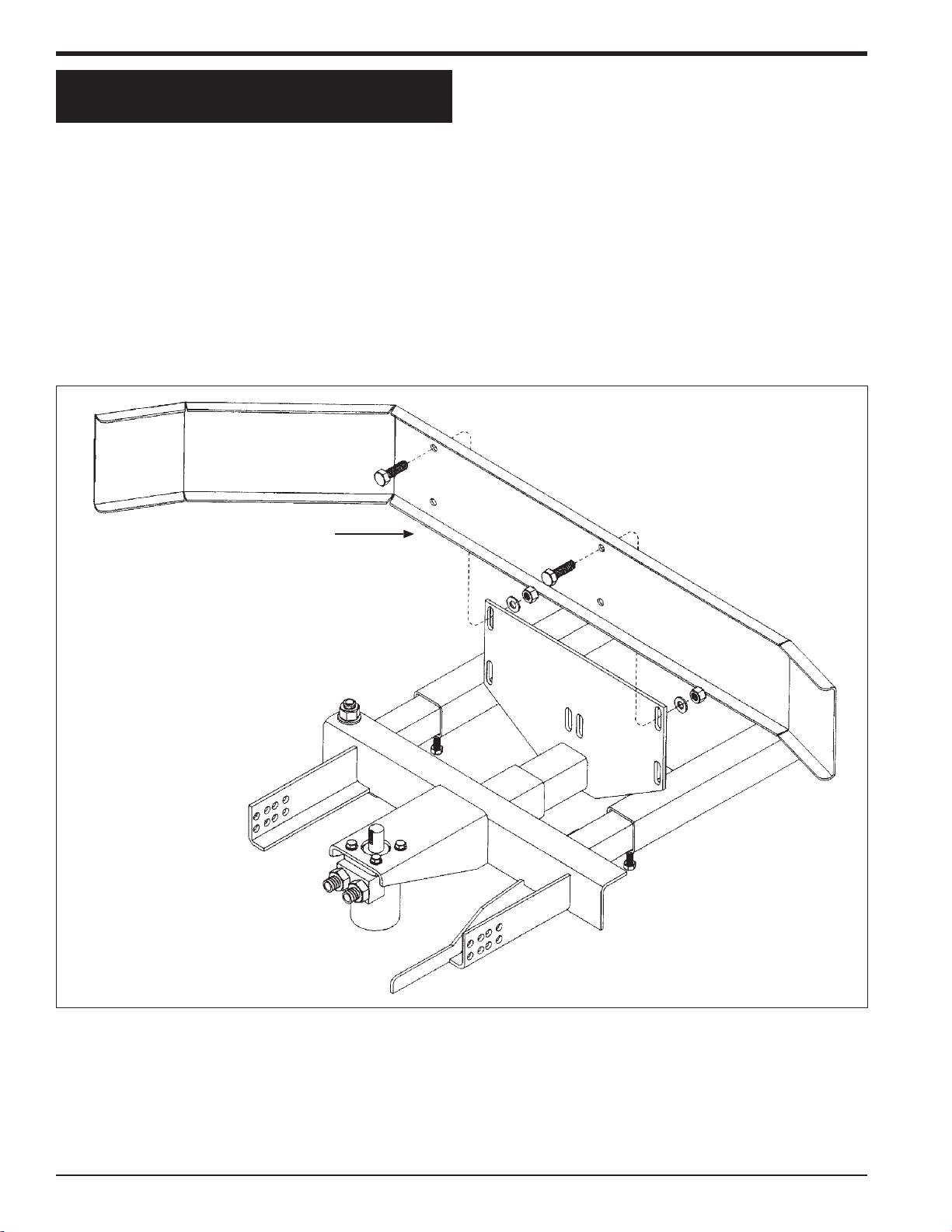
10 CYCLONE CHAFF SPREADER - JD
BASIC ASSEMBLY
Figure 4.2 Single Spinner models
Figure 4.3 Double Spinner models
Bolt Holes
Axle Mount
Frame
Motor Mount Assembly
Angled Bolt Tube
▲
▲
▲
▲
▲
Motor Mount Assembly
Angled Bolt Tube Axle Mount Frame
Bolt Holes
▲
▲
▲
▲

11
CYCLONE CHAFF SPREADER - JD
BASIC ASSEMBLY
4.3 INSTALL FRONT SHIELD MOUNTING
BRACKET (BOTH MODELS)
Figure 4.4 Single Spinner
Front Shield
Mounting
Bracket
▲
Figure 4.5 Double Spinner
FrontShield Mounting
Bracket
▲
The front shield mounting bracket allows adjustment of the
shields distance from the spinner. Some adjustment may
be required for individual conditions.
1. Slide the front shield mounting assembly into the front
openinginthemotor mountassemblyasshownin figure
4.4 (for single spinner models) or figure 4.5 (for double
spinner models).
Final adjustment to this piece will be required later.
12 CYCLONE CHAFF SPREADER - JD
BASIC ASSEMBLY
Assemble the front shield with the formed end facing back
onthe left side. The holes should now line up withtheholes
in the mounting bracket.
1. Securethefrontshieldtoitsmounting bracket with four
provided 1/2 x 1" bolts, flat washers on each side of
shield, and locknuts with the shield held in place. Bolts
go through the shield, then through the bracket.
2. Tighten locknuts according to torque specifications.
Figure 4.6 Single Spinner Shield Mounting Diagram
Front
Shield
4.4 SHIELD MOUNTING: SINGLE SPINNER
MODELS

13
CYCLONE CHAFF SPREADER - JD
BASIC ASSEMBLY
The front shield on double spinner models is a two piece
designandassemblesto curveaway fromthecombine. The
holes in each shield piece align with the mounting bracket
holes previously installed.
1. Inserttwo1/2x 1" bolts with washers through the lower
two bolt holes located at the ends of the shields with
each shield held in place as shown.
4.5 SHIELD MOUNTING: DOUBLE SPIN-
NER MODELS
2. Insert the bolts from Step 1 into the two holes in the
centerofthe front shield mounting bracket. Secure with
two 1/2" washers and nuts.
3. Align the front deflector shield with the four bolt holes
in the shield and shield mounting bracket.
4. Insert four 1/2 x 1" bolts with washers through the de-
flectorshield,front shield, and shield mounting bracket.
Secure with four 1/2" washers and nuts.
Figure 4.7 Double Spinner Shield Mounting Diagram
Front Deflec-
tor Shield
Front Shield Half) Front Shield (Half)

14 CYCLONE CHAFF SPREADER - JD
BASIC ASSEMBLY
1. Loosen the set screws in the spinner disc hub to allow
mounting on the hydraulic motor shaft.
2. Situated the motor key to fit into the hub.
3. Position the spinner disc so the motor key aligns with
the keyway in the spinner disc hub by holding the spin-
nerdiscinboth hands with the hub pointing downward.
4. Push the spinner disc onto the hydraulic motor shaft
as far as possible.
4.6 SPINNER DISC MOUNTING: SINGLE
SPINNER
5. Insert a supplied 1/4 x 3/4" bolt and 1/4" flat washer
through the spinner disc and into the end of the hy-
draulic motor's shaft.
6. Tighten 1/4 x 3/4" bolt very securely (see torque chart
on page 1).
7. Tighten the set screw on the key.
8. Tighten the set screw on the shaft. Make sure both set
screws are torqued to specifications.
IMPORTANT
Checkfor clearancebyrotating thediscby handtomake
sureallbladesare clear of obstructions. If the disc does
not spin freely, the installation is incorrect.
Figure 4.8 Single Spinner Disc Mounting Diagram
Spinner Disk Hub
Hydraulic Mo-
tor Shaft
NOTE
Exceeding 400 RPM may damage the motor. Set the
flow control to a value of 4 to prevent the spinners from
operating in excess of 400 RPM.

15
CYCLONE CHAFF SPREADER - JD
BASIC ASSEMBLY
1. Loosen the set screws in the spinner disc hub to allow
mounting on the hydraulic motor shafts.
2. Situate the motor key to fit into the hubs.
3. Position the spinner disc so the left motor key aligns
with the keyway in the spinner disc hub by holding the
left spinner disc in both hands with the hub pointing
downward.
4. Push the spinner disc onto the hydraulic motor shaft
as far as possible.
5. Insert a supplied 1/4" x 3/4" bolt and 1/4" flat washer
throughthespinner disc and into the end of the hydrau-
lic motor's shaft.
Figure 4.9 Double Spinner Disc Mounting and Tilting Diagram
4.7 SPINNER DISC MOUNTING AND
TILTING: DOUBLE SPINNER
NOTE
The left spinner blades bend in the clockwise direction
around the disc, the right spinner blades bend in the
counterclockwise direction.
6. Tighten these bolts very securely (see torque chart).
7. Tighten the key set screws.
8. Tighten the set screw on the shaft.
9. Mount the right spinner by repeating the above steps.
Crary Tilting Double Cyclones have the unique ability to tilt
eachdisc to adjustformaximum trajectory and tocleartires.
At the motor mount assembly under each disc:
1. Loosen the pivot bolt and adjustment bolt.
2. Adjust to desired setting (up to ten degrees).
3. Retighten. IMPORTANT
Check for clearance by rotating each disc by hand to
ensureallbladesare clear of obstructions. If the discs
do not spin freely, the installation is incorrect.
Adjustment Bolt (un-
der plate)
Pivot Bolt
Spinner
Disk Hub
Motor Key
Hydraulic Mo-
tor Shaft
NOTE
Exceeding 400 RPM may damage the motor. Set the
flow control to a value of 4 to prevent the spinners from
operating in excess of 400 RPM.

16 CYCLONE CHAFF SPREADER - JD
BASIC ASSEMBLY
4.8 MOUNTING REAR SHIELD:
SINGLE SPINNER
1. Holding the rear shield with its curved side to your
right and pointing away from you, approach the shield
mounting bracket from the rear.
2. Checkthedistance oftheshield from thespinner.Clear-
ance should be approximately 2 inches if working with
corn,and1/2inch for all other crops. Choose mounting
holes on the motor mount assembly accordingly.
Figure 4.10 Mounting Rear Shield
Rear Shield
Shield Mounting
Bracket
3. Secure the rear shield to the shield mounting bracket
with four 1/2 x 1-1/2" bolts, 1/2" flat washers and lock-
nuts (all supplied).
4. Tighten 1/2" bolts under left and right adjustment tubs.
This manual suits for next models
12
Table of contents


