Douglas Dynamics Western Striker 98805 User manual

July 1, 2020
Lit. No. 74126, Rev. 00
Western Products, PO Box 245038, Milwaukee, WI 53224‑9538 • www.westernplows.com
Striker™ Hopper Spreader
0.35 yd3& 0.7 yd3
#98805, 98810
Owner's Manual
Original Instructions
This manual supersedes all editions with an earlier date.
CAUTION
Read this document before operating
or servicing the spreader.
This Owner's Manual is for Striker hopper spreaders
with serial numbers beginning with 200706 and higher.


Lit. No. 74125/74126, Rev. 00 3 July 1, 2020
TABLE OF CONTENTS
PREFACE................................................................... 4
Owner's Information Form .................................... 4
SAFETY ..................................................................... 5
Safety Denitions.................................................. 5
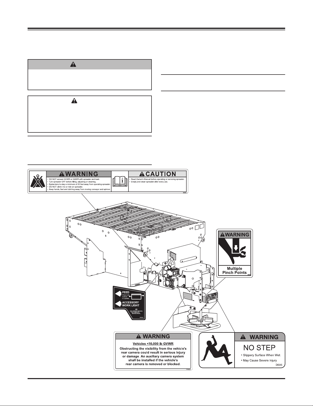
Warning/Caution Labels ....................................... 5
Serial Number Label ............................................. 7
Safety Precautions................................................ 7
Fuses .................................................................... 8
Personal Safety..................................................... 8
Fire and Explosion ................................................ 8
Cell Phones........................................................... 8
Ventilation ............................................................. 9
Battery Safety ....................................................... 9
Noise..................................................................... 9
Vibration................................................................ 9
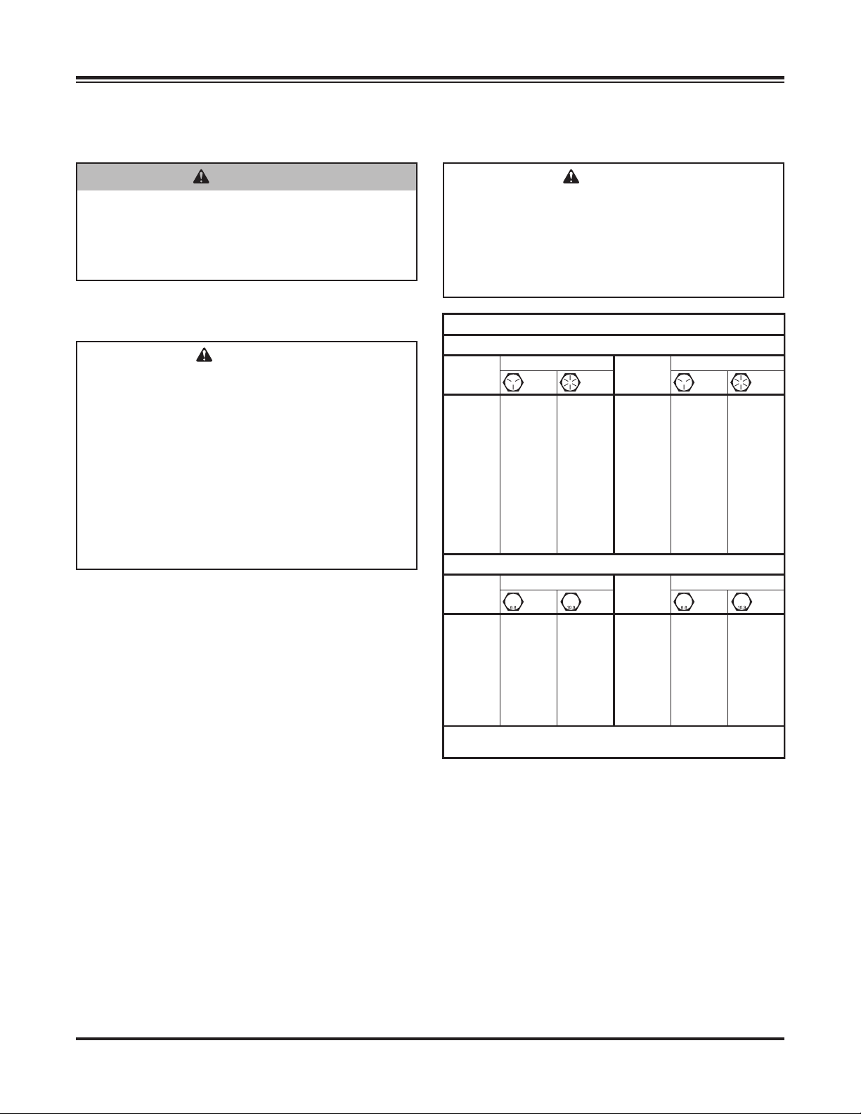
Torque Chart ......................................................... 9
LOADING ................................................................. 10
Certication......................................................... 10
Spreader Specications...................................... 10
Material Weights ................................................. 10
Load Volume ....................................................... 11
Determining Vehicle Payload.............................. 11
Determining Vehicle Payload Worksheet............ 12
UNPACKING THE SPREADER............................. 13
Remove Shipping Brackets and Locate
Components .................................................... 13
MOUNTING THE SPREADER............................... 14
Chute Assembly.................................................. 14
Install Hopper in Vehicle Bed.............................. 14
Install Tie-Down Straps ................................ 15
Construct Sill Spacer.................................... 15
Install Spinner Drive Assembly ........................... 16
OPERATING THE SPREADER—CAB CONTROL 17
Powering the Control .......................................... 17
Starting and Stopping Spreader ......................... 17
Controlling Material Application .......................... 18
BLAST/Maximum Application ...................... 18
Cab Control Modes............................................. 18
Standby Mode .............................................. 18
Ready Mode ................................................. 18
ON Mode ...................................................... 18
Error Mode ................................................... 18
Cab Control Codes – Table ............................... 19
Setup Procedures ............................................... 21
Calibrate the Empty Hopper Setting............. 21
Adjust LED Brightness Level........................ 21
OPERATING THE SPREADER ...............................22
Spread Pattern Adjustment.................................22
Material Spread Patterns.............................. 23
Accessory LED Work Light ................................. 24
Dump Function.................................................... 24
Remove Spreader from Vehicle.......................... 25
Store the Spreader ............................................. 25
MAINTENANCE ...................................................... 26
After First Use .....................................................26
After Each Use.................................................... 26
Cab Control......................................................... 26
Storage ...............................................................26
At the End of Each Season or
After Extended Storage ................................... 26
Fuse Replacement.............................................. 26
Recycle ...............................................................26
Grease Fittings ................................................... 27
ELECTRICAL COMPONENTS .............................. 28
Vehicle Harness Diagram ................................... 28
Electrical Control Box .........................................29
FINAL ADJUSTMENTS.......................................... 30
Conveyor Pintle Chain Tension........................... 30
TROUBLESHOOTING GUIDE............................... 31

Lit. No. 74126, Rev. 00 4 May 1, 2020
PREFACE
This manual has been prepared to acquaint you with
the safety information, operation, and maintenance of
your new hopper spreader. Please read this manual
carefully and follow all recommendations. This will
help ensure protable and trouble-free operation of
your hopper spreader. Keep this manual accessible. It
is a handy reference in case minor service is required.
When service is necessary, bring your hopper
spreader to your distributor. They know your spreader
best and are interested in your complete satisfaction.
NOTE: This spreader is designed to spread snow
and ice control materials only. Do not use it
for purposes other than those specied in this
manual.
Register your spreader online at www.westernplows.com
OWNER'S INFORMATION
Owner's Name: ______________________________________________________________________
Date Purchased: _____________________________________________________________________
Outlet Name: ______________________________________________ Phone:_________________
Outlet Address: ______________________________________________________________________
Vehicle Model: _______________________________________________ Year: _______________
Spreader Type (Model):________________________________ Serial #:______________________
Length:________________________ Weight: __________________ lb/kg: _________________

Lit. No. 74125/74126, Rev. 00 5 July 1, 2020
SAFETY
SAFETY DEFINITIONS
NOTE: Indicates a situation or action that can lead
to damage to your spreader and vehicle or other
property. Other useful information can also be
described.
WARNING/CAUTION LABELS
Become familiar with and inform users about the
warning and caution labels on the spreader.
NOTE: If labels are missing or cannot be read, see
your sales outlet.
CAUTION
Indicates a potentially hazardous situation
that, if not avoided, may result in minor or
moderate injury. It may also be used to alert
against unsafe practices.
WARNING
Indicates a potentially hazardous situation
that, if not avoided, could result in death or
serious personal injury.

Lit. No. 74125/74126, Rev. 00 6 July 1, 2020
0.7 yd³ hoppers only
(0.35 yd³ hoppers
have no cross bar).

Lit. No. 74125/74126, Rev. 00 7 July 1, 2020
SAFETY
SAFETY PRECAUTIONS
Improper installation and operation could cause
personal injury and/or equipment and property
damage. Read and understand labels and the
Owner's Manual before installing, operating, or making
adjustments.
WARNING
• Driver to keep bystanders minimum of
25 feet away from operating spreader.
• Before working with the spreader, secure all
loose-tting clothing and unrestrained hair.
• Before operating the spreader, verify that all
safety guards are in place.
• Before servicing the spreader, wait for
conveyor, auger, and spinner to stop.
• Do not climb into or ride on spreader.
WARNING
Do not install the control for this product in
the deployment path of an air bag. Refer to
vehicle manufacturer's manual for air bag
deployment area(s).
WARNING
Overloading could result in an
accident or damage. Do not
exceed GVWR or GAWR ratings
as found on the driver‑side
vehicle door cornerpost. See Loading section
to determine maximum volumes of spreading
material.
Code Denition
YY 2-Digit Year
MM 2-Digit Month
DD 2-Digit Day
LL 2-Digit Location Code
XXXX 4-Digit Sequential Number
ZZZZZZ 5- to 7-Digit Assembly PN
SERIAL NUMBER LABEL
WARNING
With chute removed, use dump switches to
operate conveyor.
WARNING
Vehicles <10,000 lb GVWR: Obstructing
the visibility from the vehicle's rear camera
could result in serious injury or damage. An
auxiliary camera system shall be installed
if the vehicle's rear camera is removed or
blocked.

Lit. No. 74125/74126, Rev. 00 8 July 1, 2020
SAFETY
CAUTION
If rear directional, CHMSL light, or brake
stoplights are obstructed by the spreader, the
lights shall be relocated, or auxiliary directional
or brake stoplights shall be installed.
CAUTION
Disconnect electric and/or hydraulic power
and tag out if required before servicing or
performing maintenance.
NOTE: Lubricate grease ttings after each use.
Use a good quality multipurpose grease.
FUSES
The electrical system contains several blade-style
automotive fuses. If a problem should occur and fuse
replacement is necessary, the replacement fuse must
be of the same type and amperage rating as the original.
Installing a fuse with a higher rating can damage the
system and could start a re. Fuse Replacement,
including fuse ratings and locations, is located in the
Maintenance section of this Owner's Manual.
PERSONAL SAFETY
• Remove ignition key and put the vehicle in PARK
or in gear to prevent others from starting the
vehicle during installation or service.
• Wear only snug-tting clothing while working on
your vehicle or spreader.
• Do not wear jewelry or a necktie, and secure long
hair.
• Wear safety goggles to protect your eyes from
battery acid, gasoline, dirt, and dust.
• Avoid touching hot surfaces such as the engine,
radiator, hoses, and exhaust pipes.
• Always have a re extinguisher rated BC handy,
for ammable liquids and electrical res.
FIRE AND EXPLOSION
Be careful when using gasoline. Do not use gasoline
to clean parts. Store only in approved containers away
from sources of heat or ame.
CELL PHONES
A driver's rst responsibility is the safe operation of
the vehicle. The most important thing you can do
to prevent a crash is to avoid distractions and pay
attention to the road. Wait until it is safe to operate
mobile communication equipment such as cell phones,
text messaging devices, pagers, or two-way radios.
CAUTION
DO NOT leave unused material in
hopper. Material can freeze or solidify,
causing unit to not work properly.
Empty and clean after each use.
CAUTION
During the hopper installation we recommend
the addition of an OSHA compliant Backup
Alarm. This alarm is required for OSHA
governed employers.
WARNING
Gasoline is highly ammable and gasoline
vapor is explosive. Never smoke while
working on vehicle. Keep all open ames
away from gasoline tank and lines. Wipe up
any spilled gasoline immediately.
CAUTION
• Do not operate a spreader in need of
maintenance.
• Before operating the spreader, reassemble
any parts or hardware removed for cleaning
or adjusting.
• Before operating the spreader, remove
materials such as cleaning rags, brushes,
and hand tools from the spreader.
• Before operating the spreader, read the
engine owner's manual, if so equipped.
• While operating the spreader, use auxiliary
warning lights, except when prohibited by law.
• Tighten all fasteners according to the
Torque Chart. Refer to Torque Chart for the
recommended torque values.

Lit. No. 74125/74126, Rev. 00 9 July 1, 2020
SAFETY
VENTILATION
BATTERY SAFETY
NOISE
Airborne noise emission during use is below 70 dB(A)
for the spreader operator.
VIBR ATION
Operating spreader vibration does not exceed 2.5 m/s2
to the hand-arm or 0.5 m/s2to the whole body.
TORQUE CHART
1/4-20 10
91
54
1/4-28 12
11
71
5/16-1
81
50 212
5/16-2
41
70 240
3/8-16 269 376
3/8-24 29
74
20
7/16-1442
96
06
7/16-20
9/16-12
9/16-18
5/8-11
5/8-18
3/4-10
3/4-16
7/8-9
7/8-14 47
46
69
64
49
091-8
1-12 70
49
95
1/2-13
1/2-20
11.9
13.7
24.6
27.3
43.6
26.9
53.3
93
148
49.4
69.8
77.9
106.4
120.0
8.4
9.7
17.4
19.2
30.8
35.0
49.4
55.2
75.3
85.0
M6 x 1.00
M12 x 1.75
M8 x 1.25
M14 x 2.00
M10 x 1.50
M27 x 3.00
M22 x 2.50
M30 x 3.50
M24 x 3.00
M20 x 2.5011.1
19.5
38.5
67
107
7.7
613
778
1139
1545
450
428
562
796
1117
M33 x 3.50
M36 x 4.00
2101
2701
1468
1952
325
M16 x 2.00 231167
M18 x 2.50 318222
Recommended Fastener Torque Chart
Size Size
Torque (ft-lb)
Grade
5
Grade
8
Metric Fasteners Class 8.8 and 10.9
These torque values apply to fasteners
except those noted in the instructions.
Torque (ft-lb)
Grade
5
Grade
8
Size Size
Torque (ft-lb)
Class
8.8
Class
10.9
Torque (ft-lb)
Class
8.8
Class
10.9
Inch Fasteners Grade 5 and Grade 8
CAUTION
Batteries normally produce explosive gases
which can cause personal injury. Therefore,
do not allow ames, sparks, or lit tobacco
to come near the battery. When charging or
working near a battery, always cover your
face and protect your eyes, and also provide
ventilation.
• Batteries contain sulfuric acid, which burns
skin, eyes, and clothing.
• Disconnect the battery before removing or
replacing any electrical components.
CAUTION
Read instructions before assembling.
Fasteners should be nger tight until
instructed to tighten according to the Torque
Chart. Use standard methods and practices
when attaching spreader, including proper
personal protective safety equipment.
WARNING
Vehicle exhaust contains lethal fumes.
Breathing these fumes, even in low
concentrations, can cause death. Never
operate a vehicle in an enclosed area without
venting exhaust to the outside.

Lit. No. 74125/74126, Rev. 00 10 July 1, 2020
LOADING
SPREADER SPECIFICATIONS
Hopper
Model
Overall
Length
(in)
Bed
Length
(in)
Empty
Weight
(lb)
Overall
Width
(in)
Bed
Height
(in)
Capacity
Struck
(yd³)
0.35 yd³ 52 28 235 38 24 0.35
0.7 yd³ 82 54 419 43 27.5 0.7
This Owner's Manual covers vehicles that have been
recommended for carrying the hopper spreader. Please
see your local dealer for proper vehicle applications.
CERTIFICATION
WARNING
Overloading could result in an accident or
damage. Do not exceed GVWR or GAWR as
found on the driver‑side cornerpost of vehicle.
WARNING
New untitled vehicle installation of a spreader
requires National Highway Trac Safety
Administration altered vehicle certication
labeling. Installer to verify that struck load of
snow or ice control material does not exceed
GVWR or GAWR rating label and complies
with FMVSS.
CAUTION
Read and adhere to manufacturer's
ice‑control material package
labeling, including Safety Data
Sheet requirements.
MATERIAL WEIGHTS
Density
Material (lb/ft3)(lb/yd3)(kg/m3)
Salt 80 2160 1282
Sand 100 2700 1602
Material densities are approximate and are based on dry,
loose material. It is the responsibility of the operator to
know the weight of the material to be spread and the vehicle
carrying capacity.
CAUTION
Never use wet materials or materials with
foreign debris with any of these spreaders.
These units are designed to handle dry, clean,
free-owing material.

Lit. No. 74125/74126, Rev. 00 11 July 1, 2020
DETERMINING VEHICLE PAYLOAD
1. Install the hopper spreader and optional
equipment according to the Installation
Instructions.
2. Install or attach any other equipment that will be
on the vehicle while the hopper spreader will be in
use (step bumper, trailer hitch, snowplows, etc.).
Fill gas tanks.
3. Obtain the Gross Vehicle Weight Rating (GVWR),
Front Gross Axle Weight Rating (FGAWR), and
Rear Gross Axle Weight Rating (RGAWR) from
the certication label located inside the driver-side
door jamb or door.
4. With the occupants in the truck for normal hopper
spreader operation, weigh the vehicle to obtain
gross vehicle weight (GVW).
5. Subtract the GVW from the GVWR to determine
the available material payload.
6. Obtain the weight per cubic yard (lb/yd3) of the
desired material. Divide the weight into the
payload to determine the maximum volume of
material that can be carried.
7. Refer to the Load Volume table and diagrams to
determine the maximum ll level for the material.
8. Fill the hopper with material to the calculated level.
Reweigh the vehicle with occupants and verify that
the Loaded Gross Vehicle Weight, Front Gross
Axle Weight, and Rear Gross Axle Weight are less
than the vehicle's ratings.
9. Repeat Steps 6–8 for each type of material.
The worksheet for Determining Vehicle Payload (next
page) includes an example.
WARNING
Overloading could result in an accident or
damage. Do not exceed GVWR or GAWR
ratings as found on the driver‑side door
cornerpost of the vehicle. See Loading
section to determine maximum volumes of
spreading material.
LOADING
Hopper
Model
Load Volume (yd3)
ABCD
0.35 yd³ 0.4 0.35 0.2 0.03
0.7 yd³ 0.85 0.7 0.4 0.06
LOAD VOLUME
A
B
C
D
A: Rounded Load
B: Struck Load
C: Second Bump
D: First Bump

Lit. No. 74125/74126, Rev. 00 12 July 1, 2020
Determining Vehicle Payload Worksheet
Material Type Example:
Dry Salt
AEquipment installed when
vehicle was weighed
8' Stainless
Steel Hopper
Spreader
BFront Gross Axle Weight
Rating [FGAWR] (lb) 6000
CRear Gross Axle Weight
Rating [RGAWR] (lb) 7000
DGross Vehicle Weight
Rating [GVWR] (lb) 11,000
EGross Vehicle Weight [GVW],
empty (lb) – 7402
F Payload Available (lb) = 3598
GMaterial Density (lb/yd3)÷ 2160
HMaximum Volume (yd3)= 1.67
I
Maximum Material Fill Level,
approx. Refer to Load Volume
table and diagrams.
C
J
Loaded Front Gross Axle
Weight (lb) Must be less than
weight in Row B.
K
Loaded Rear Gross Axle
Weight (lb) Must be less than
weight in Row C.
L
Loaded Gross Vehicle Weight
[GVW] (lb) Must be less than
weight in Row D.
LOADING

Lit. No. 74125/74126, Rev. 00 13 July 1, 2020
REMOVE SHIPPING BRACKETS AND
LOCATE COMPONENTS
The spreader is shipped from the factory with its
components secured inside the hopper and the top screen
in place. Before installation of the spreader, remove
shipping brackets and top screen, and locate components.
For 0.35 yd3 hopper spreaders:
1. Take o the top screen by removing the 3/8" anged
cap screws and the top screen brackets. Set the
screen and all fasteners aside for reinstallation.
2. Inside the hopper, remove the eight 3/8" steel cap
screws from the two shipping brackets that secure
the chute enclosure to the hopper for shipment. Set
the chute enclosure aside and discard the brackets
and hardware.
3. Install the provided 3/8" stainless steel anged
cap screws from the parts bag to fasten the
hopper body to the drivetrain.
4. On the shipping pallet, remove the two 5/16" lag
bolts and the shipping bracket that fasten the
spinner deector assembly to the pallet. Remove
the 1/4" hardware that fastens the shipping bracket
to the spinner deector assembly. Set the spinner
deector assembly aside and discard the shipping
bracket and hardware.
UNPACKING THE SPREADER
For 0.7 yd3hopper spreaders:
1. Take o the top screen by removing the 3/8" anged
cap screws and the top screen brackets. Set the
screen and all fasteners aside for reinstallation.
2. Inside the hopper, remove the 3/8" steel cap screws
from the four shipping brackets (two on each side) that
secure the chute enclosure and the spinner deector
assembly to the hopper for shipment. Set the chute
enclosure and spinner deector assembly aside, and
discard the brackets and hardware.
3. Immediately install the six supplied 3/8" stainless steel
anged cap screws from the parts bag to fasten the
hopper body to the drivetrain.
Remove brackets.
Remove brackets.

Lit. No. 74125/74126, Rev. 00 14 July 1, 2020
INSTALL HOPPER IN VEHICLE BED
NOTE: Periodically throughout the snow and ice
control season, verify that mounting devices
are secure.
1. Remove the vehicle tailgate.
2. Remove the wood shipping rails from the hopper legs.
3. Using slings or chains, lift the spreader by the four
diagonal corner rails and move it into the vehicle bed.
4. Center the spreader from side to side. Shift the
spreader forward or backward to a position that
will allow the chute, once installed, to overhang
the rear of the vehicle and the bumper. With two
people, trial-t the chute to check for clearance.
CHUTE ASSEMBLY
1. To complete assembly of the chute, orient the
spinner guard as shown. Fasten the spinner
deector assembly to the chute enclosure using
four 3/8” anged cap screws from the parts bag.
No nuts are required as rivnuts are installed on the
chute enclosure.
2. Remove the cable boot bracket and dust cover,
setting them and fasteners aside. Using the
driver-side and passenger-side chute pin ears and
six 3/8” stainless steel anged cap screws from
the parts bag, fasten to chute enclosure as shown
above. Reinstall the cable boot bracket and dust
cover.
3. After assembling the chute, set aside for
installation on the spreader after the spreader has
been installed on the vehicle.
CAUTION
Before lifting, verify that the hopper is empty
of material. The lifting device must be able to
support the spreader's weight as shown in
the Spreader Specications table.
MOUNTING THE SPREADER
Use all four rails
when lifting.
Chute Pin Ears
Spinner Guard
3/8" Flanged
Cap Screws

Lit. No. 74125/74126, Rev. 00 15 July 1, 2020
MOUNTING THE SPREADER
CAUTION
Before drilling holes, check to be sure that no
vehicle wiring or other components could be
damaged.
5. Using the holes in the four hopper support legs
as a template, mark mounting hole positions on
the vehicle bed. Move the spreader temporarily to
allow access, and drill 5/8" holes as marked.
NOTE: Pay special attention when drilling or
clamping dissimilar metals to aluminum bodies.
Galvanic corrosion can occur if not handled
properly. Contact vehicle manufacturer for
recommended attachment practices.
WARNING
Spreader shall be bolted to vehicle frame.
Do not rely on the tie‑down chains or straps
alone to hold spreader in vehicle.
6. Move the spreader back into position. Install
the spreader to the vehicle bed using four
5/8" Grade 5 bolts as required by the vehicle
application, 5/8" at washers on both sides, and
5/8" locknuts. (Fasteners supplied by installer.)
If the mounting holes are not directly over the
vehicle box supports, the vehicle bed must
be braced to the frame to prevent buckling or
deforming the vehicle bed. Accessory mounting
bars are available for installations that require
additional bracing. Contact your authorized dealer.
7. Remove the cable tie holding the wire harness
to the conveyor chain. Connect the vehicle-side
harness to the hopper-side harness.
8. Install the top screens, using the retained linch
pins to secure the screens to the previously
installed brackets.
Holes in the Four
Hopper Support Legs

Lit. No. 74125/74126, Rev. 00 16 July 1, 2020
SPINNER DRIVE ASSEMBLY
INSTALL SPINNER DRIVE ASSEMBLY
NOTE: Complete the assembly installation in the
Install Chute Assembly section before proceeding
with these instructions.
1. Carefully set the spinner drive assembly on the
ground. Orient it in operating position as shown
below.
2. Install the lock pins found in the parts bag
to attach the spinner drive assembly to the chute
supports. Install the top lock pin rst, using the
lower holes in the chute supports. Secure each
lock pin with a cotter pin.
3. Connect the spinner motor harness to the female
connector extending from the rear of the hopper.
Lock
Pins
Cotter
Pins
Install Tie‑Down Straps
Install tie-down straps from the tie-down loops on the
spreader body to the truck frame. Use one strap per
loop, pulling diagonally away from the hopper body.
Construct Sill Spacer
Measure the distance from the front end of the hopper
sill to the front of the vehicle bed and make a spacer
from 2" x 8" lumber to t that area.
Failure to install a spacer could result in damage
to the spreader.
Front of
Tr
uck Bed
Measure distance.
Spacer
Built to Fit
Measured
distance.
2"x 8" Construction
Fit to vehicle.
18"

Lit. No. 74125/74126, Rev. 00 17 July 1, 2020
OPERATING THE SPREADER – CAB CONTROL
POWERING THE CONTROL
Power is not applied to the control until the vehicle
ignition is turned to ACC or ON. Once the control
has power it performs a light check and displays the
software version on the status display. The control
then checks for a connected spreader. If no spreader
is detected, the control does the following:
• nC (no connection) appears on the red status
display for ve seconds;
• A single beep;
• Control enters Standby mode with no lights
illuminated.
If any button is pressed on the control, it will wake and
check again for spreader connection. If no spreader is
detected, it will act as described above. If a spreader
is detected, it will transition to Ready mode.
STARTING AND STOPPING SPREADER
To start the spreader, press the ON/OFF button. The
control backlights are illuminated when the vehicle
ignition is ON and the spreader is connected. When
the spreader is ON, the ON/OFF button and inner arc
around each control knob will also illuminate.
To stop the spreader, press the ON/OFF button
again.
The ON/OFF button also operates as an emergency
stop when required.
NOTE: The vehicle ignition must be ON to start
the spreader.
NOTE: If vehicle ignition is turned OFF while
spreader is running, the motors will stop.
Material
Width
Material
Flow
VIBRATELIGHT STROBE PREWET
MINMAX
ON/OFF
MI
NM
AX
BLAST
Material Width
Control Knob
(spinner speed)
Indicator Lights
(8 per knob)
Material Flow
Control Knob
(feed rate)
BLAST Button
(maximum application)
ON/OFF Button
& Emergency Stop
Status/Error Code
Display (red)
Accessory
Control Buttons
WARNING
Before starting the spreader, the driver shall
verify that all bystanders are a minimum of
25 feet away from operating spreader.
WARNING
Never operate equipment when under the
inuence of alcohol, drugs, or medications that
might alter your judgment and/or reaction time.
WARNING
Never exceed 45 mph (72 km/h) when loaded
spreader is attached to vehicle. Braking
distances may be increased and handling
characteristics may be impaired at speeds
above 45 mph (72 km/h).
WARNING
Never allow children to operate or climb on
equipment.

Lit. No. 74125/74126, Rev. 00 18 July 1, 2020
OPERATING THE SPREADER – CAB CONTROL
CONTROLLING MATERIAL
APPLICATION
The material application settings can be adjusted
while spreader is ON or OFF. Settings are shown by
the indicator lights around the control knobs. When
the spreader is OFF, a single LED will light to show the
current setting. When the spreader is ON, the number
of blue LEDs illuminated will increase/decrease as the
knobs are turned clockwise/counterclockwise.
The hopper drive will not deliver material until the ON
button is pressed.
The Material Width (left) knob controls spinner speed.
Turning the knob clockwise will increase the width of
the application area.
The Material Flow (right) knob controls the hopper
drive. Turning the knob clockwise will increase the
feed rate of material to the spinner.
Turning the control knobs counterclockwise will
decrease the width of the application area and the
feed rate of material, respectively.
BLAST/Maximum Application
1. Press and hold the BLAST button when maximum
ow rate and application area are needed
temporarily. The BLAST button will illuminate
while depressed.
2. Release the button when maximum application
settings are no longer needed.
NOTE: Spinner speed and material feed rate revert
to the previous settings once the BLAST button
is released.
CAB CONTROL MODES
Standby Mode
Vehicle ignition is set to ACC or ON; cab control is
OFF. Control has power. No spreader was detected.
No lights are illuminated on the control. Press any
button to wake.
Ready Mode
Vehicle ignition is set to ACC or ON; cab control is OFF.
Control has power. Spreader is detected.
The Material Width and Material Flow control knobs
can be set to start-up conditions, but the spinner and
drives will not operate until the cab control is turned
ON.
Accessory lights and vibrator (if installed) are
operational. The BLAST function is not operational.
ON Mode
Vehicle ignition is set to ACC or ON; cab control is ON.
Spinner and hopper motors will start. All cab control
functions are operational. Accessory lights and
vibrator (if installed) are operational.
During normal spreader operation, no control codes
are displayed. Information or setup codes will appear
when relevant. These codes will not stop spreader
operation.
Error Mode
When an error condition occurs, spreader operation
will shut down. A two-character error code will ash
on the display and a beep will sound. If there are
multiple error codes, the codes will ash in a repeating
sequence.
Refer to the Error Codes portion of the
following Cab Control Codes table. Also see the
Troubleshooting Guide section of this manual.
Once the error condition has been resolved, press the
ON/OFF button to clear the error code(s). Press the
ON/OFF button again to resume spreader operation.
The error code will reappear if the error condition
has not been rectied. If the error condition persists,
contact your authorized dealer.
Multiple resets within a short time frame will cause
the hopper module to time out if components are
overheating. The control will display an EF error code.
Accessory work lights and strobe lights can be used
when an error code is in eect and will remain in their
current state. The vibrator and pre-wet, if installed, will
not function.

Lit. No. 74125/74126, Rev. 00 19 July 1, 2020
OPERATING THE SPREADER – CAB CONTROL
Error Codes – Spreader Operation Stopped
Code Denition Possible Cause Suggested Solution
bb Bad button. Button is stuck.
Button was pressed while
vehicle ignition was entering
ACC or START mode.
Inspect control. Free up button.
Do not press any spreader cab control buttons
while the vehicle ignition is being engaged.
bH Bad hopper. Possible module or control
mismatch.
Replace control or module. Use only genuine
service parts. Contact authorized dealer.
CE No communication with
spreader module.
Loose connection.
Module lost power.
Conrm that spreader and control harnesses are
connected to the vehicle harness. Check power
to spreader module, all connections, fuses, and
power studs. Check that B port is plugged in.
CP Chute present fault. Chute is open.
Bad connection at chute position
mag switch. (Can occur when
driving on rough surface.)
Close the chute. Reset the control by pressing the
ON/OFF button.
If CP code continues to display, contact
authorized dealer.
Ct Control is hot. Cab temperature is too high.
Control overheated.
Turn spreader OFF and allow control to cool o.
Setup Codes
Code Denition Procedure
Cb Calibrate the Empty Hopper setting. With control in ON mode, press and hold the left control knob until the
Cb code displays. Calibration cycle is automatic.*
Cc Clear calibration data for Empty Hopper
setting; clear EH code.
Press the right control knob to clear all calibration data during the
calibration cycle.
LS Set LED brightness level. With control in Ready mode, press and hold left control knob to get
LS code. Release pressure and turn left control knob to desired
brightness setting. Wait for conrming SL code to display.*
SL Conrms that LED brightness level has
been reset.
* For full instructions, see the "Setup Procedures" section.
Information Codes
Code Denition Response
dU Spreader is in dump mode:
• Material chute is open.
• Back Dump buttons are enabled.
To operate the dump function, see instructions in the Operating the
Spreader section of this manual.
If dU code displays when the material chute is closed and latched,
contact authorized dealer.
EH Empty hopper (beep will sound). Check hopper for material.
Recalibrate Empty Hopper setting as described above for Cb code.
Lb Low battery. Hopper module is sensing
< 10V. (Lb becomes an error code
when module senses < 6V.)
Refer to the Lb row under "Error Codes" (next table).
CAB CONTROL CODES
Table continues on next page.

Lit. No. 74125/74126, Rev. 00 20 July 1, 2020
OPERATING THE SPREADER – CAB CONTROL
Error Codes – Spreader Operation Stopped
Code Denition Possible Cause Suggested Solution
EF Excessive drive faults. Too many HO and/or SO
error codes; hopper module
overheating.
Control times out for 60 seconds.
Ensure that conveyor and/or spinner are not
jammed.
HO Hopper overload –
software trip.
Drive system has high current.
Material is jammed.
Chain is damaged.
Inspect conveyor; clear material jam or x chain
as needed.
HO . Hopper overload –
hardware trip.
HP Hopper power issue.
No motor present.
Hopper drive motor is not
connected.
Possible motor defect.
Check connections to the conveyor drive motor
(P—FEED and GND posts on the module and
studs on the motor).
Replace the motor.
Lb Low battery. Hopper
module is sensing ≤ 6V.
Bad connection or low battery.
Snowplow or other vehicle
power use may be driving
down voltage.
Voltage is measured at the hopper module, so
Lb code may indicate cable voltage loss. Check
battery, alternator, and connections.
nC No connection. Spreader not connected to
vehicle harness.
Connect vehicle and spreader harness.
Check vehicle harness fuse.
Inspect spreader and vehicle harnesses.
Check module.
OH Overheating. Spreader module is too hot.
Spreader module malfunction.
Accessories wiring/function
problem.
Drive motor overload.
Allow a cool-o period of 60 seconds or longer.
Check for loose harness connections.
Check accessory connections. Check integrity of
accessory wiring and harness.
Clear jammed material.
Contact authorized dealer.
OH . Overheating module –
microprocessor.
rS Reset of spreader module. Power loss to module detected
on startup.
Reset the control by pressing the ON/OFF button.
Check vehicle harness and battery connection.
SO Spinner drive overload –
software trip.
Material jammed in chute.
Spinner shaft is damaged.
Inspect spinner and spinner drive components for
alignment and condition.
Adjust and replace parts as required.
SO . Spinner drive overload –
hardware trip.
SP Spinner power issue.
No motor present.
Spinner drive motor is not
connected.
Possible motor defect.
Check connections to the motor (SPIN and GND
posts on the module).
Replace the motor.
CAB CONTROL CODES continued
This manual suits for next models
1
Table of contents
Other Douglas Dynamics Spreader manuals

Douglas Dynamics
Douglas Dynamics Western Plows 85695 User manual

Douglas Dynamics
Douglas Dynamics 85689 User manual

Douglas Dynamics
Douglas Dynamics SnowEx HELIXX 1.5 yd3 User manual

Douglas Dynamics
Douglas Dynamics SnowEx V-Pro SP-2000 User manual

Douglas Dynamics
Douglas Dynamics SnowEx HELIXX Series User manual