Creations SIAI MARCHETTI SF260 User manual
SIAI MARCHETTI SF 260
The SIAI MARCHETTI SF260 is an exceptional
military training aircraft.
Designed in the 60's, it is still much better today
than most modern aircraft.
The characteristics of its wing give it
a ight behavior close to that of a warbird.
Like the original, this sports model has fantastic ying qualities.
The radio controlled model that we suggest you to print
is a faithful reproduction on a 1/7th scale
of the SIAI MARCHETTI SF260.
llhinfo.com
facebook.com/llhinfo
Créations

Main characteristics
Wingspan : 1,260 m.
Length : 0.96 m.
Filament required for printing : approx. 1100 g.
Takeo weight : less than 2000 g.
Radio: minimum 6 channels (engine, ailerons, rudder, aps, elevator, retractable gear).
Autonomy : around 5 min with LIPO 3s 2600 mAh battery.
Propeller : 11x5,5 ou 11x6.
Motor : approximately 1450Kv Brushless 650w to 700 W with LIPO 3S 2600 mAh battery.
approximately 1000Kv Brushless 650w to 700 W with LIPO 4S 2200 mAh battery.
Maximum battery size (excluding prominence of cable outlet) :
length 145 mm, width: 43 mm, height 35 mm.
ESC : around 60 A.
Servos : 6 mini servos.
Maximum size of the servo housing (recessed part):
length 23 mm, width 12.5 mm, depth 23 mm.
List of RC equipment used on the SIAI MARCHETTI SF260
Propeller : 11x5,5
motor : Turnigy D3542 / 4 1450KV Brushless Outrunner Motor 690w
ESC : Hobby roi 60A ESC 4A UBEC
Battery : LIPO 3s 2600 mAh
Servos : 6 mini servos Hextronik MG-14 (22.8x12x31mm)
Landing gear : The model was designed to receive a retractable landing gear
"Turnigy MCR All Metal Retract System (Small) (ref. 107000048) disponible at hobbyking".
Due to the physical constraints that these mechanisms undergo, we recommend, after checking
their proper functioning and before installing them, to lubricate the gears and tighten all the screws
correctly using thread locker.
Wheels :We do not recommend printing the rims and tires of the SF260.
Indeed, experience has shown us that wheels with foam tires are clearly preferable, be-
cause they are lighter, more resistant and the rolling is much more flexible and silent.
front landing gear (one wheel) : 55 x 18 mm.
main landing gear (two wheels) : 60 x 18 mm.
WARNING! This radio controlled model is NOT A TOY !
It is intended for already experienced pilots of aircraft models. If modied or own
carelessly it could go out of controll and cause serious human injury or proper-
ty damage. Before ying your airplane, ensure the aireld is spacious enough.
Always y it in safe and authorized areas.
> Editor's note
The designers of the product you just bought thank you and count on you not to copy it or
distribute it "illegally".
The survival of developers, and therefore the future of these products, is at stake.
2

3D Printer and software
3D printer printing volume : at least 20 cm x 20 cm x 20 cm.
Slicing software : Simplify3D®.
Other softwares are possible but will require modifying and mixing the generated “gcode” les
using a text editor.
MATERIALS USED for building the model
8 mm diameter carbon ber tube : 160 cm
6 mm diameter carbon ber tube : 9 cm (for optional exhaust pipes)
5 mm diameter carbon ber tube : 5 cm
4 mm diameter carbon ber tube : 50 cm
2 mm diameter carbon ber rod : 150 cm
1 mm diameter piano wire : 4 cm
1.5 mm diameter piano wire : 50 cm
2 mm diameter piano wire : 40 cm
3 mm diameter piano wire : 25 cm
4 x 3 brass tube : 19 mm
Écrous M3 : 18
Écrous M3 type nylstop (autoblocants) : 2
Écrous M6 : 2
Countersunk head screw M3 x 8 mm : 4
Screw M3 x 10 mm : 9
Screw M3 x 15 mm : 1
Screw M3 x 20 mm : 4
Screw M3 x 28 mm : 1
Screw BTR M3 x 10 mm : 1
Washer internal diameter 3 mm : 1
Washer internal diameter 4 mm : 2
Countersunk head self-tapping screw 3 mm x 10 mm : 8
Countersunk head self-tapping screw 2 mm x 10 mm : 1
Countersunk head self-tapping screw 2 mm x 6 mm : 1
Countersunk head self-tapping screw 2 mm x 10 mm : 2
Nylon screw M6 mm x 44 mm : 2
(wing-fuselage attachment)
Pen-spring : 1
Dominos for 1.5 mm diameter rods : 3
Ball link for 1.5 mm diameter rods : 1
Pushrods for rudder and elevator max. diameter1.8 mm x 50 cm : 2
3

V3D printer printing volume : at least 20 cm x 20 cm x 20 cm.
Slicing software : Simplify3D®.
Other softwares are possible but will require modifying and mixing the generated “gcode” les
using a text editor.
Some useful tools
For this printed aircraft to give complete satisfaction, it must be beautiful, light and resistant.
Without apparent defects.
Using the minimum of material.
By obtaining the best possible coherence between the printed layers.
To achieve these results, we must understand how the pieces are printed.
For the SIAI MARCHETTI SF 260, you must:
A 3D printer equipped with a 0.4 mm diameter nozzle.
No low quality lament, it's a safety issue.
By prioritizing quality over speed,
the total printing time will be approximately 115 hours.
Printing the plane :
3D PRINTER
4
The machine must be calibrated :
- In dimensions : Check that the printed objects are exactly the size expected in the three directions
x, y, z.
- In extrusion : With an extrusion coecient of 100%, the printer must generate single walls exactly
0.42 mm thick (measure in the center of a single wall at least 10 cm long), because most of the
pieces will be printed on a single wall, ie with a "skin" of a single perimeter.
With such precision requested, if the printer is not very rigid, not stable, the belts are slack, the extru-
sion does not have a constant value or the extrusion temperature uctuates, it will not be possible
to obtain an acceptable model.
The provided "gcode" les were made for an ordinary printer equipped with direct extrusion.
They may require manual modication of the extrusion and temperature values to suit your machine.

CREATING A BASIC
PRINTING PROFILE for the Marchetti SF260
Refer to your filament manufacturer's data for a basic extrusion temperature.
With the machine connected and hot, place a mark 15 cm upstream of the extruder and deliver 10
cm of lament. The mark must be exactly 5cm in front of your extruder.
If this is not the case, the extrusion is not calibrated, it is necessary to modify the value of "steps/
mm" in the printer rmware.
With all the calibrations done, here's how to set up a basic profile :
Extrusion multiplier : 0.93
Extrusion width : 0,42 mm
Layer height : 0.25 mm
Retraction : as usual (from 0,5 to 2,0 mm for direct drive extrusion,
and 1,5 to 6 mm for remote extrusion with "Bowden" tube).
Top solid layers : 0
Bottom solid layers : 0
Outline/perimeter shells : 1
First layer height : 100% (imperative value)
First layer width : 100 % (modiable according to the grip needed to the bed).
Inll : 0%
Extrusion temperature : 210°C à 230°C according to specications of the lament used.
Cooling : 0%, then 30% to 50% from the third layer.
Speed : 60 mm/s
Movement speed : depending on printer capacity, from 100 to 150 mm/s
> Import the «sf260_aile_c.stl» file in your slicer software
Specify the starting point of the layers so that it is on the trailing edge side and on the
underside of the wing.
Make a first test on a height of 2 cm maximum.
The layers must be consistent :
By pushing the wall with a nail, the part must be marked, but must not break.
If the layers separate eortlessly, increase the extrusion temperature in increments of 5° C.
Be careful however, too high a temperature will not be able to manage the retractions.
If lament drips during movements of the print head, forming wires inside the part (stringing), it is
necessary to increase the retraction distance (increasing the speed of free movements can improve
if the machine is rigid enough).
If there is a lack of lament after the retractions (thinning of the wall or hole), the retraction distance
must be reduced until the wires reappear.
5

Then increase the additional restart distance (the extruder pushes back the lament a little more
than the retraction value.
If stopping the movement at the time of the retractions creates lamentary blobs, it is possible to
add a declutching distance before the retractions (coasting at end).
It is all a matter of compromise, some large printers with very long Bowden tubes may not be able
to be calibrated to perfection.
> Print the entire room. It should weigh around 53 g.
If the resulting part is greater than this value, decrease the extrusion coecient and recalibrate
until the expected value is obtained.
Make a backup of the resulting prole as it will serve as a basis for almost all parts of
the aircraft.
Printing parts requiring several printing processes :
Either for technical reasons or for aesthetic reasons, several parts of the model contain several
printing processes.
For now, Simplify3D® is the only slicing software allowingthis task to be easily carried out.
As a owner of Simplify3D®, the provided «factory» les only need to be adapted to the specics
of your printer.
Other slicing software requires compiling a gcode le by prole and then manually combining these
gcode les into one. Some tutorials are available on the internet.
Pay particular attention to the "starting point" of the printed layers because the retractions made by
the machine can be particularly unsightly if they are located in an inappropriate location.
For all these settings, refer to the "Setup" folder provided for each part.
6

DÉSIGNATION stl le left & right
part factory le Unit weight Qty
AILE A sf260_aile_a.stl sf260_aile_a 60.50 g 1
AILE B sf260_aile_b.stl sf260_aile_b 65.25 g 1
AILE C sf260_aile_c.stl L & R sf260_aile_c 52.30 g 2
AILE D sf260_aile_d.stl L & R sf260_aile_d 38.10 g 2
AILE E sf260_aile_e.stl L & R sf260_aile_e 27.30 g 2
RÉSERVOIR A FUELA sf260_tank_a.stl L & R sf260_tank_a 9.40 g 2
RÉSERVOIR B FUELB sf260_tank_b.stl L & R sf260_tank_b 6.50 g 2
RÉSERVOIR C FUELC sf260_tank_c.stl L & R sf260_tank_c 0.10g 2
NAVLIGHT sf260_navlight.stl twin parts sf260_lights 0.10 g 2
PHARE sf260_phare.stl sf260_lights 0.80 g 1
FEU DÉRIVE sf260_light1.stl sf260_lights 1
FEU ARRIÈRE sf260_light2.stl sf260_lights 1
CACHE AILERON sf260_cacheservo.stl sf260_caches 1.00 g 2
CACHE TRAIN PRINCIPAL sf260_cachetrain.stl sf260_caches 1.00 g 2
AILERON A sf260_aileron_a.stl L & R sf260_aileron_a 11.70 g 2
AILERON B sf260_aileron_b.stl L & R sf260_aileron_b 3.45 g 2
VOLET A sf260_ap_a.stl L & R sf260_ap_a 7.50 g 2
VOLET B sf260_ap_b.stl L & R sf260_ap_b 9.50 g 2
RONDELLE sf260_rondelle.stl sf260_acc_2 0.80 g 2
GUIDE TRAIN sf260_guidetrain.stl sf260_acc_3 1.35 g 1
FUSELAGE NEZ sf260_noze.stl sf260_noze 12.00 g 1
FUSELAGE A sf260_fuse_a.stl sf260_fuse_a 133.00 g 1
FUSELAGE B sf260_fuse_b.stl sf260_fuse_b 112.00 g 1
FUSELAGE C sf260_fuse_c.stl sf260_fuse_c 69.00 g 1
FUSELAGE B ET C sf260_fuse_bc.stl sf260_fuse_bc 1
FUSELAGE D sf260_fuse_d.stl sf260_fuse_d 57.00 g 1
FUSELAGE E sf260_fuse_e.stl sf260_fuse_e 28.00 g 1
FUSELAGE D ET E sf260_fuse_de.stl sf260_fuse_de 1
VERROU A sf260_verrou_a.stl sf260_verrou 1
VERROU B sf260_verrou_b.stl sf260_verrou 5.05 g 1
PLAQUE_AILEA1 sf260_plaque_aileA1.stl sf260_plaques 3.70 g 1
PLAQUE_AILEA2 sf260_plaque_aileA2.stl sf260_plaques 0.70 g 1
PLAQUE_AILEB sf260_plaque_aileB.stl sf260_plaques 4.30 g 1
PLAQUE_FUSEB sf260_plaque_fuseB.stl sf260_plaques 1.35 g 1
EMPENNAGE sf260_stab.stl L & R sf260_stab 18.20 g 2
VOLET PROFONDEUR A sf260_voletprof_a.stl sf260_voletprof_a 11.00 g 2
VOLET PROFONDEUR B sf260_voletprof_b.stl sf260_voletprof_b 1.25 g 2
GUIGNOL PROFONDEUR sf260_horn_elev.stl sf260_acc_1 0.70 g 1
GUIGNOL DÉRIVE sf260_horn_rud.stl sf260_acc_1 0.90 g 1
BATTERIE STOP sf260_batstop.stl twin parts sf260_acc_1 1.90 g 2
LEVIER VOLET sf260_horn_ap.stl sf260_acc_1 1.20 g 2
DÉRIVE sf260_derive.stl sf260_derive 19.60 g 1
PIVOT DÉRIVE sf260_derive_hinge.stl sf260_acc_3 0.70 g 1
VOLET DÉRIVE sf260_voletderive.stl sf260 voletderive 16.00 g 1
SUMMARY TABLE OF PRINTED PARTS
7

VERRIÈRE AVANT sf260_canopy_a.stl sf260_canopy_a 10.00 g 1
VERRIÈRE GRANDE sf260_canopy_b.stl sf260_canopy_b 24.00 g 1
VERRIÈRE ARCEAU sf260_canopy_c.stl sf260_canopy_c 4.60 g 1
VERRIÈRE 1/2 BANDEAU sf260_canopy_d.stl L & R sf260_canopy_d 2.70 g 2
VERRIÈRE BANDEAU sf260_canopy_dgd.stl canopy GD sf260_canopy_dgd 5.40 g 1
VERRIÈRE PLAQUE
ARRIÈRE sf260_canopy_e.stl sf260_acc_3 2.70 g 1
VERRIÈRE PLAQUE
AVANT sf260_canopy_f.stl sf260_canopy_f 4.30 g 1
VERRIÈRE 1/2 POIGNÉE sf260_canopy_g.stl sf260_acc_2 0.06 g 2
VERRIÈRE POIGNÉE sf260_canopy_h.stl sf260_acc_2 0.18 g 2
SUPPORT MOTEUR sf260_motor.stl sf260_supports 12.30 g 1
SUPPORT TRAIN AV sf260_train.stl sf260_supports 7.00 g 1
TRAPPE A (TRAIN) sf260_trappe_a.stl sf260_acc_2 3.20 g 1
TRAPPE B (TRAIN) sf260_trappe_b.stl sf260_acc_3 1.60 g 1
JAMBE A sf260_jambe A.stl sf260_jambe 6.85 g 1
JAMBE B sf260_jambe B.stl sf260_jambe 6.50 g 1
JAMBE C sf260_jambe C.stl sf260_jambe 0.60 g 1
JAMBE D sf260_jambe D.stl sf260_jambe 2.30 g 1
CÔNE PLATEAU sf260_coneB.stl sf260_coneB 7.20 g 1
CÔNE sf260_coneA.stl sf260_coneA 5.40 g 1
Principle of assembly and bonding :
- all printed parts will be glued with a medium cyano medium (CA) glue plus activator.
- all carbon tubes and piano strings should be degreased and frosted with ne sandpaper.
- all carbon tubes and piano strings will be glued with a fairly slow setting Epoxy glue.
- for metal-to-metal screw-nut attachments, always use a thread locker.
> Building the model
Preparation of parts before assembly :
Clean and sand all parts properly.
To strengthen the bonding of the fuselage parts, falls
about 11mm of laments will act as "dowels.
It is therefore necessary to drill all the housings of the "dowels"
with a 2 mm drill so that these 1.75 mm dowels
can beare easily inserted.
Lightly mill the openings of these holes
greatly facilitates the positioning of the parts
during the final bonding.
Check and finely sand all the fuselage joint surfaces if necessary.
Always check the parts by making a rst assembly without any glue.
8
FUSELAGE E
Drill and adjust the passage of the tting
connecting the elevator aps (fuseE_01).
Adjust the housing of the elevator ap axis to
2 mm.
Drill and adjust the holes for the 4 mm carbon
tube of the stabilizer.
Adjust the housing of the 2 mm rudder ap axis.
Drill and adjust the holes for the 4 mm carbon
tube of the rudder.
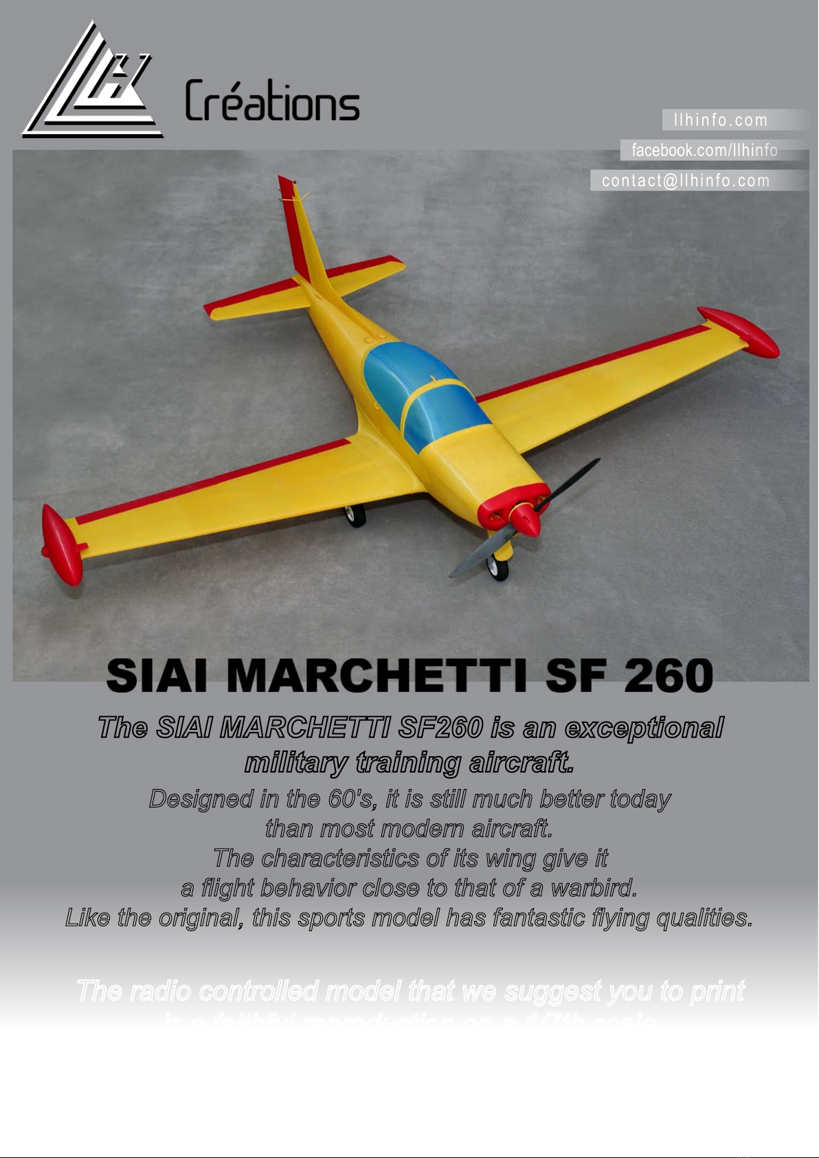
STABILIZER
Coat the left side of the carbon tube (4mm x 23.9cm) with EPOXY glue
and stick it in the left stabilizer.
Coat with EPOXY glue the tube housing in fuselage (E).
Glue with CA the left stabilizer to the fuselage.
Coat the carbon tube protruding from the fuselage with EPOXY glue.
Glue with CA the right stabilizer to the fuselage.
Fit the left elevator ap (part A).
Coat the piano wire (2 mm x 12 cm) with EPOXY glue and stick it in the left elevator ap.
Install the right elevator ap (part A).
Install the elevator ap carbon ber axis (2 mm x 40 cm).
Keep the two aps parallel during drying.
CA glue the ends of the elevator aps (parts B).
9

Coat the fuse D part (sf260_fuse_d) with CA
glue.
Glue all the dowels in the fuse D part.
Add a drop of CA glue in each dowel hole of
fuse E part (sf260_fuse_e).
Carrefully assemble Dand E, reposition
if necessary then apply the activator.
RUDDER
CA glue the rudder to fuselage E.
Assemble the rudder ap, the pivot and the car-
bon ber axis (2 mm x 18.3 cm).
Glue with CA the two parts of the canopy lock.
Coat the carbon tube (4mm x 19.4cm)
with EPOXY glue and insert it fully in the
fuselage and the rudder.
Take care not to deform the fuselage.
Adjust the canopy lock so that it can move freely in its housing.
Put the canopy lock and the spring on part C.
FUSELAGE D & E
10
Fit the rudder ap by gluing the pivot in the
rudder.

Coat the C part (sf260_fuse_c) with CA glue.
(be careful not to stick the canopy lock)
and glue all the dowels in the fuse D part.
Carrefully assemble D and E, reposition
if necessary then apply the activator..
Ensure that the canopy lock moves freely.
Drill to 3 mm the 8 pilot holes of the front landing gear and insert the 4
M3 nuts in their housings.
Using a 2 mm rod long enough to guide the nuts in their housings, install
the 4 xing nuts (M3) of the engine mount and the two nylstop nuts (M3)
of the front cover.
Bring the nuts to the bottom of their housings by tightening an M3 screw on each of them.
The nuts must hold securely in pca securely in place. Add a drop of CA glue if necessary.
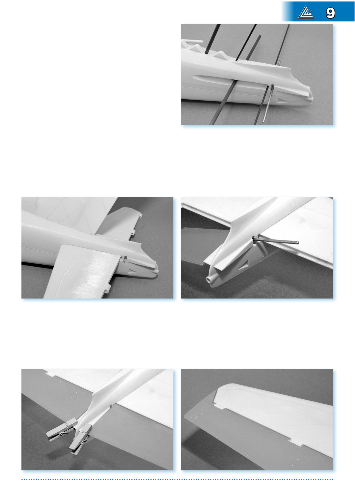
FUSELAGE B
Remove unnecessary extruded filaments
at the base of the canopy.
FUSELAGE C
The holes for the M6 wing fixing screws
are pre-drilled. Finish drilling at 6mm.
FUSELAGE C
FUSELAGE A
11
Glue Fuselage A, B, and Cusing the same method.
Glue with CA the plate plaque_fuse B
on the rear side of fuselage B.
The plate plaque_fuse B must not exceed
the fuselage B part.
For all wing parts, make sure that all 2mm axes turn easily.
For all wing parts, make sure that the 8 mm carbon tubes fit without play but with ease.
WINGS
Glue (CA) the half-aps and the half-ailerons.
WING A
Remove unnecessary extruded filaments at the front of the part.
12

The holes for the 8 mm carbon ber tube are pre-drilled. Finish drilling at 8 mm.
Make sure the 8mm carbon tube ts easily. Bore if necessary.
The holes for the M6 wing xing screws are pre-drilled. Finish drilling at 6mm.
Fit an M6 screw, a nut and a washer (do not use a too fragile nylon screw)
in the order "screw-nut washer".
Screw in an M6 nut with a few threads from the inside
Above all, do not force.
By gently tightening the outer locknut, the inner M6 nut will gradually fit into its housing until
it is flush.
Add a drop of CA glue to secure the nut in place..
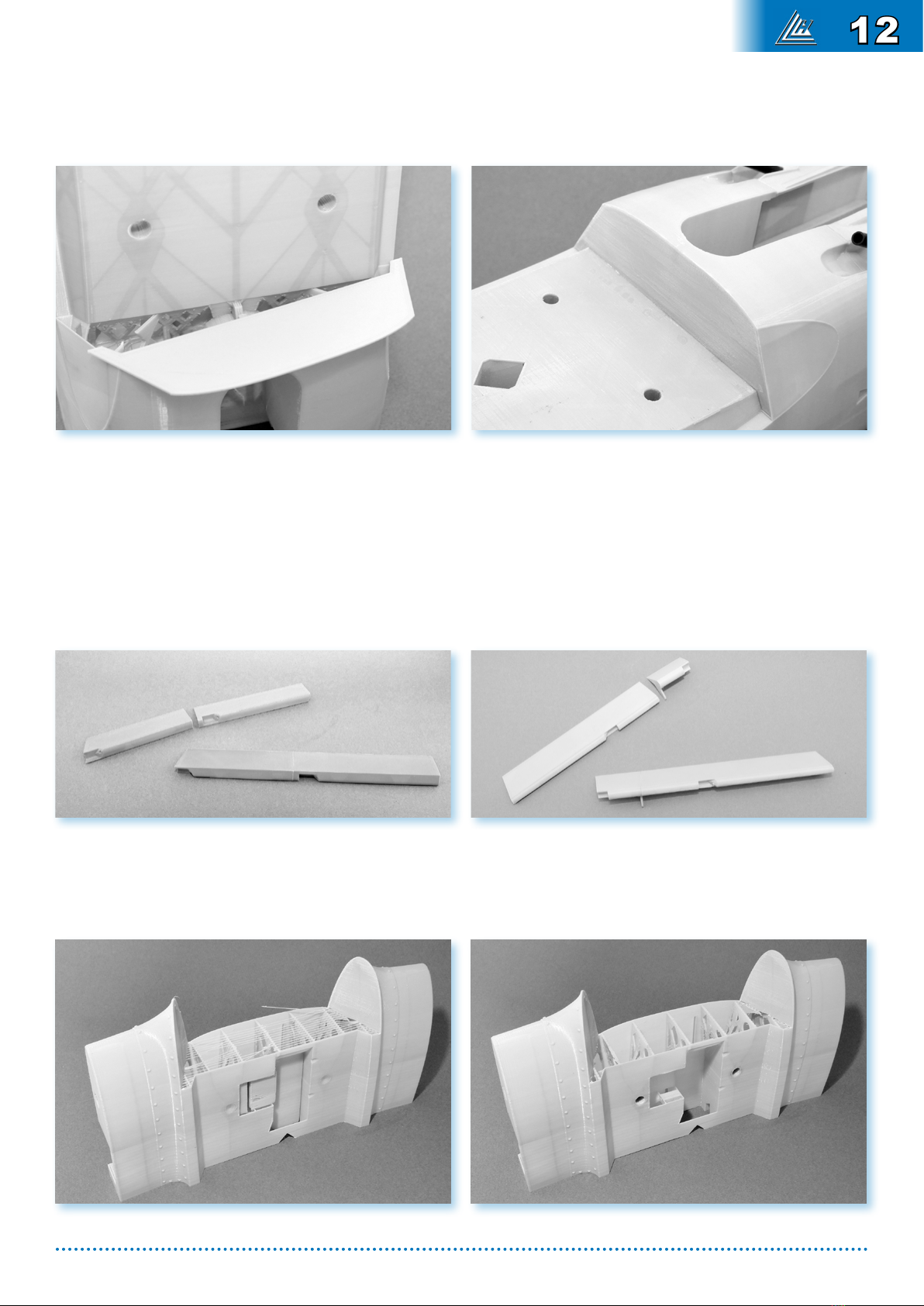
The holes for the 8 mm carbon ber tube are
pre-drilled. Finish drilling at 8 mm.
Make sure the 8mm carbon tube ts easily.
Bore if necessary.
The holes for the 2 mm aps axis are pre-drilled.
Finish drilling at 2 mm.
Make sure that the 2 mm piano wire axis t and
turn freely.
WING B
13
Glue with CA the two center wing parts
aile A and aile B using the same method as
for the fuselage
WING AB :
Sand the contact surfaces with the fuselage.
Sand the bonding surfaces with
wing C parts aile C.
Coat with EPOXY glue the carbon ber tube
(8mm x 31.6 cm) and insert it in aile A taking
care to center it.
Immediately clean the tube ends.
Coat with EPOXY glue the carbon ber tube
(8mm x 32.6 cm) and insert it in aile B taking
care to center it.
Immediately clean the tube ends.
Coat with EPOXY glue the carbon ber tube on the right side.
Glue with CA the aile C (right side part) on aile AB. Repeat operation for the left side.
Insert the 2 mm piano wire aps axis
(2 mm x 13 cm) in aile AB.
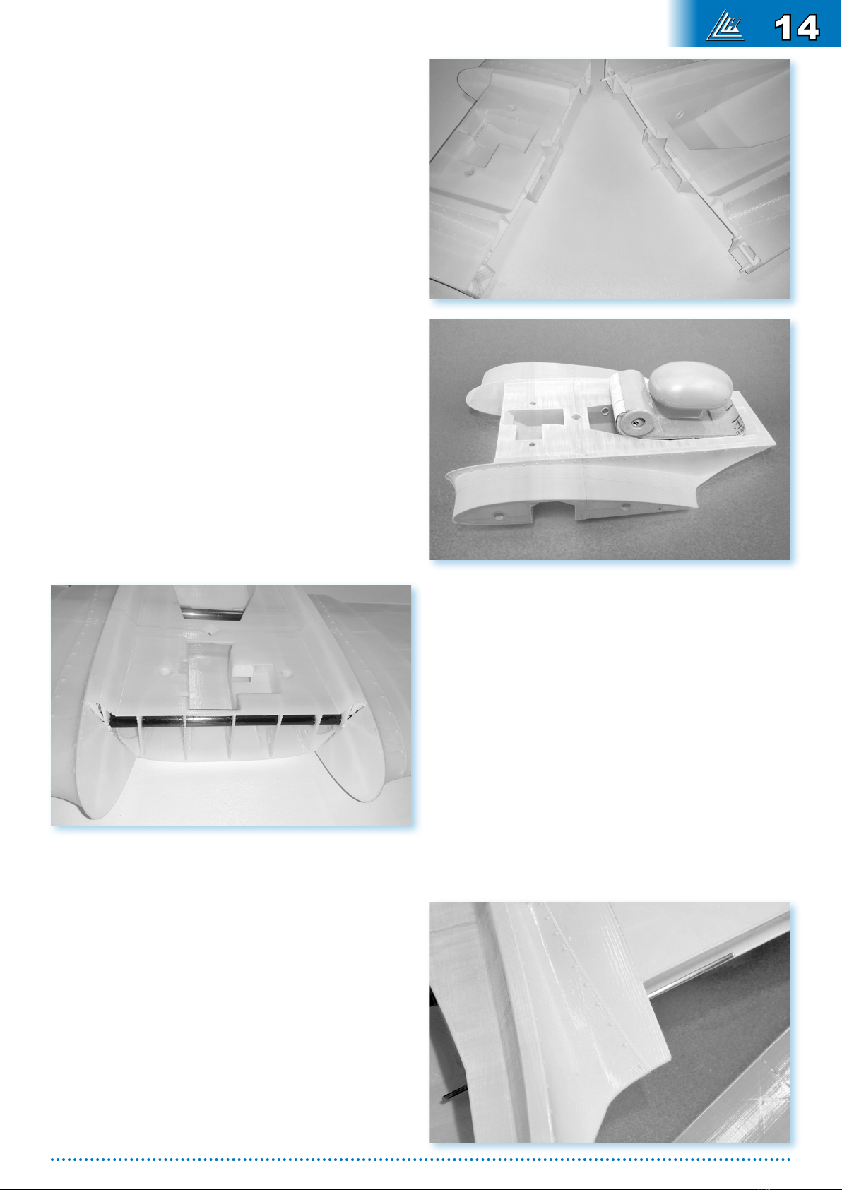
14
Coat with EPOXY glue the aps axis,
and put the aps.
Insert the 2 mm x 20,5cm carbon rod axis.
The axis must lead of 15 mm in the central wing
(AILE AB).
Do not handle before EPOXY glue
has completely dried.
CA glue aile D and aile E.
CA glue aile DE on aile ABC.
Coat with EPOXY glue the carbon ber tubes
(8 mm x 47cm) and insert them in the
wings.
Fit the ailerons and insert the carbon axis (2 mm x 25.2 cm).
Ailerons and aps must be able to operate freely.
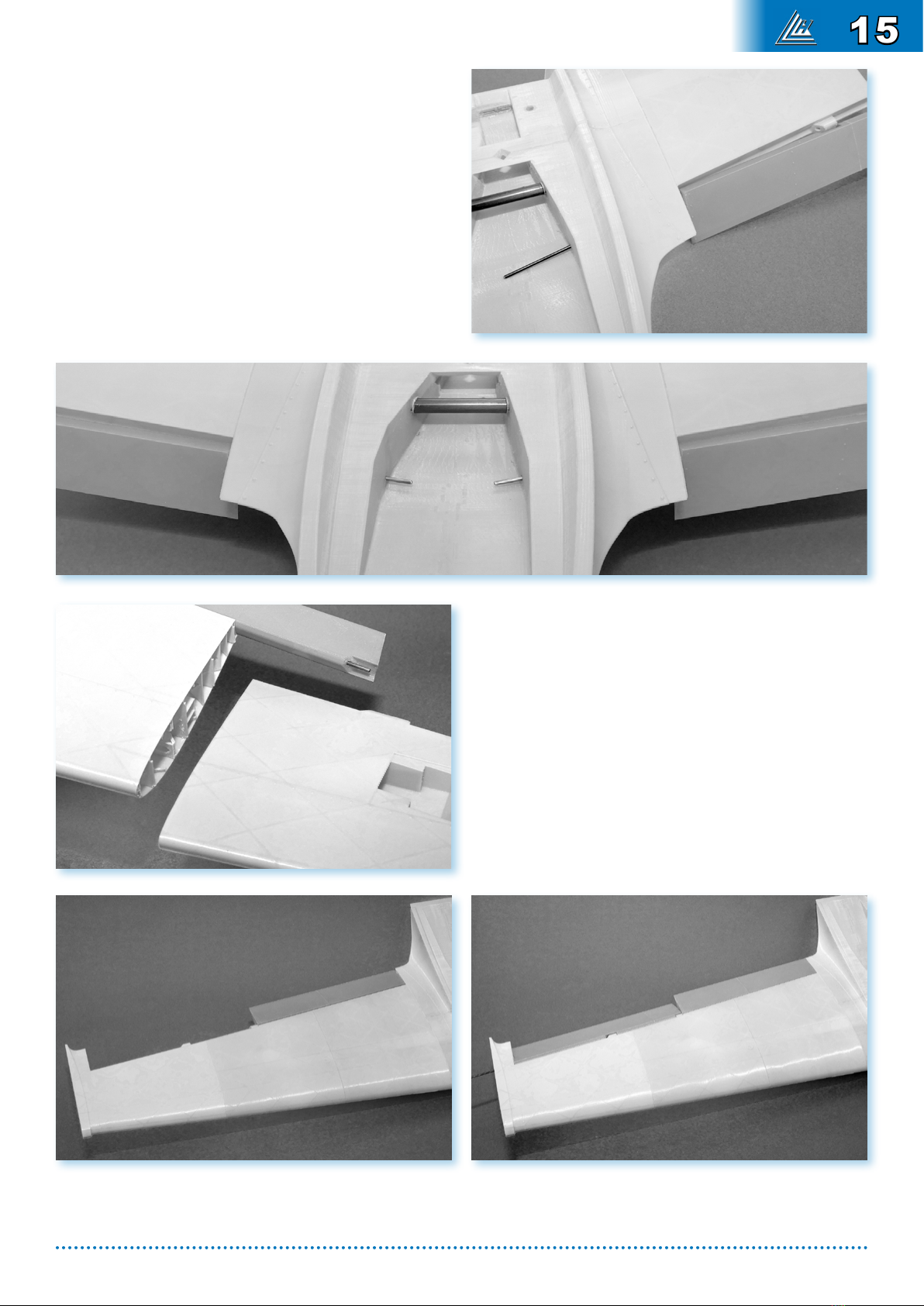
15
CA glue the two front plates
plaque_aileA1 then plaque_aileA2.
CA glue the rear plate
plaque_aileB.
EPOXY glue tthe positioning pins
(carbon tubes 5 mm x 25 mm).
The pins must protrude 10 mm from the wing.
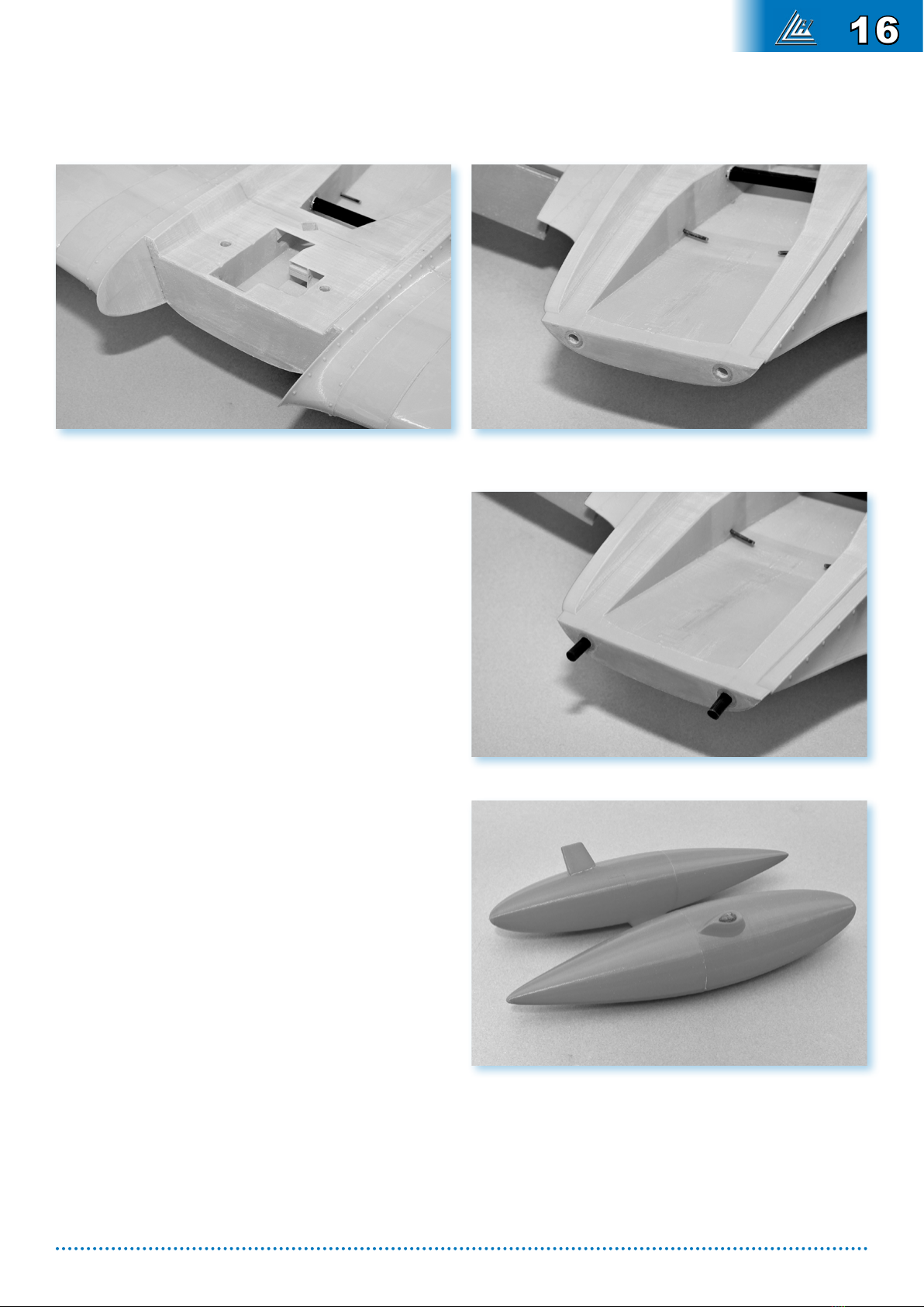
WING TANKS
CA glue tankA and tankB
(pay attention to the alignment of the parts)
and the winglet tankC.
CA glue the navlight parts
(green on the right, red on the left side).
CA glue the tanks on the the wings.
16
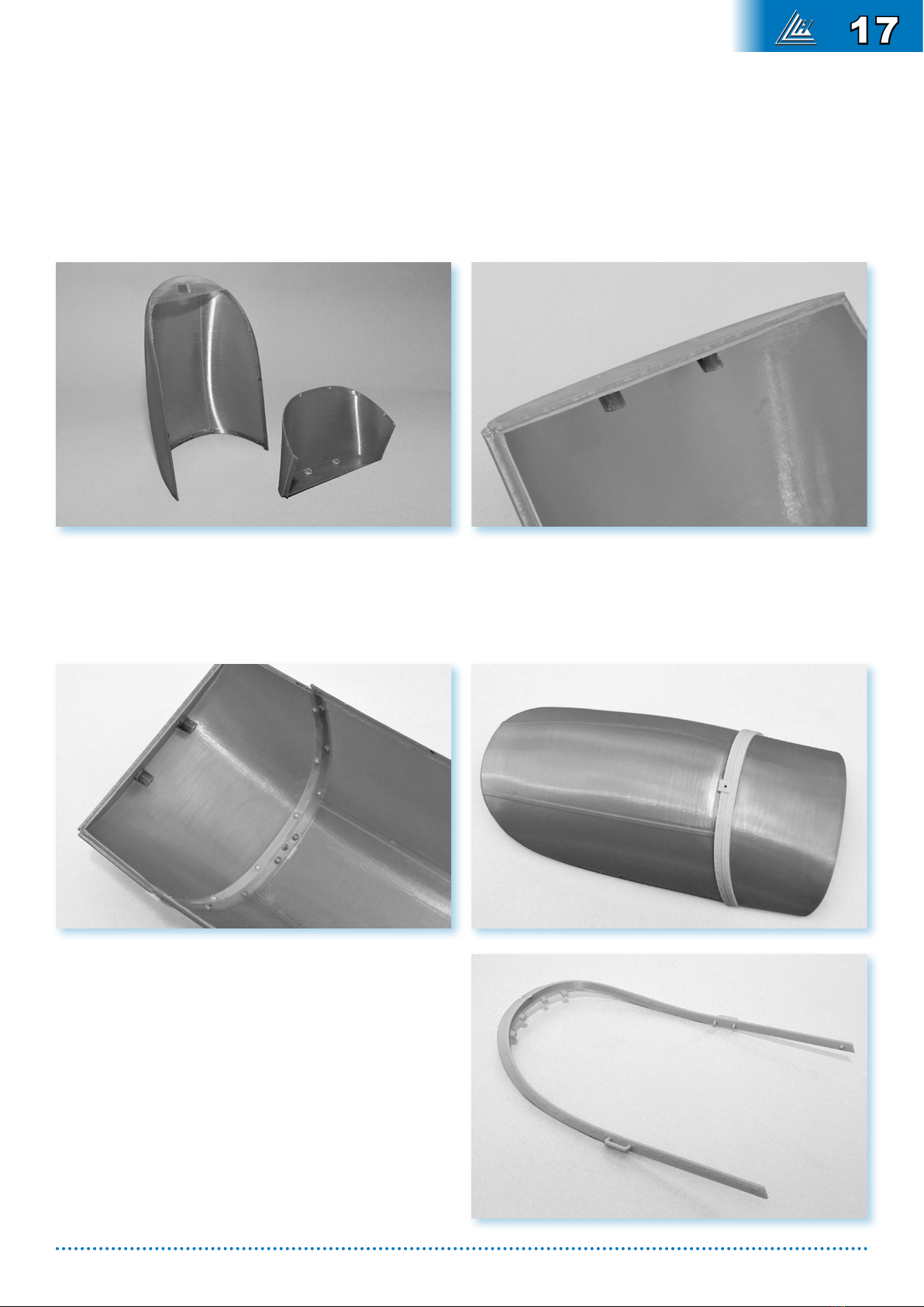
> CANOPY ASSEMBLY
Cut all unnecessary parts of canopies
canopy A et canopy B.
This work is very delicate, it is strongly recommended to protect all visible surfaces (external and
internal) of the canopy with adhesive tape.
CA glue the front part canopy F
to the canopy A part.
Make sure that all the pins of the canopyC and canopyD parts eortlessly enter their canopy
locations.
CA glue the part canopyA then canopyB to the hoop canopyC.
CA glue together the two sides of the part
canopyD.
(the part sf260_canopy_dgd.stl intended
for larger printers avoids this sticking)
CA glue the two handles canopyH on the
canopy strip canopyD.
17
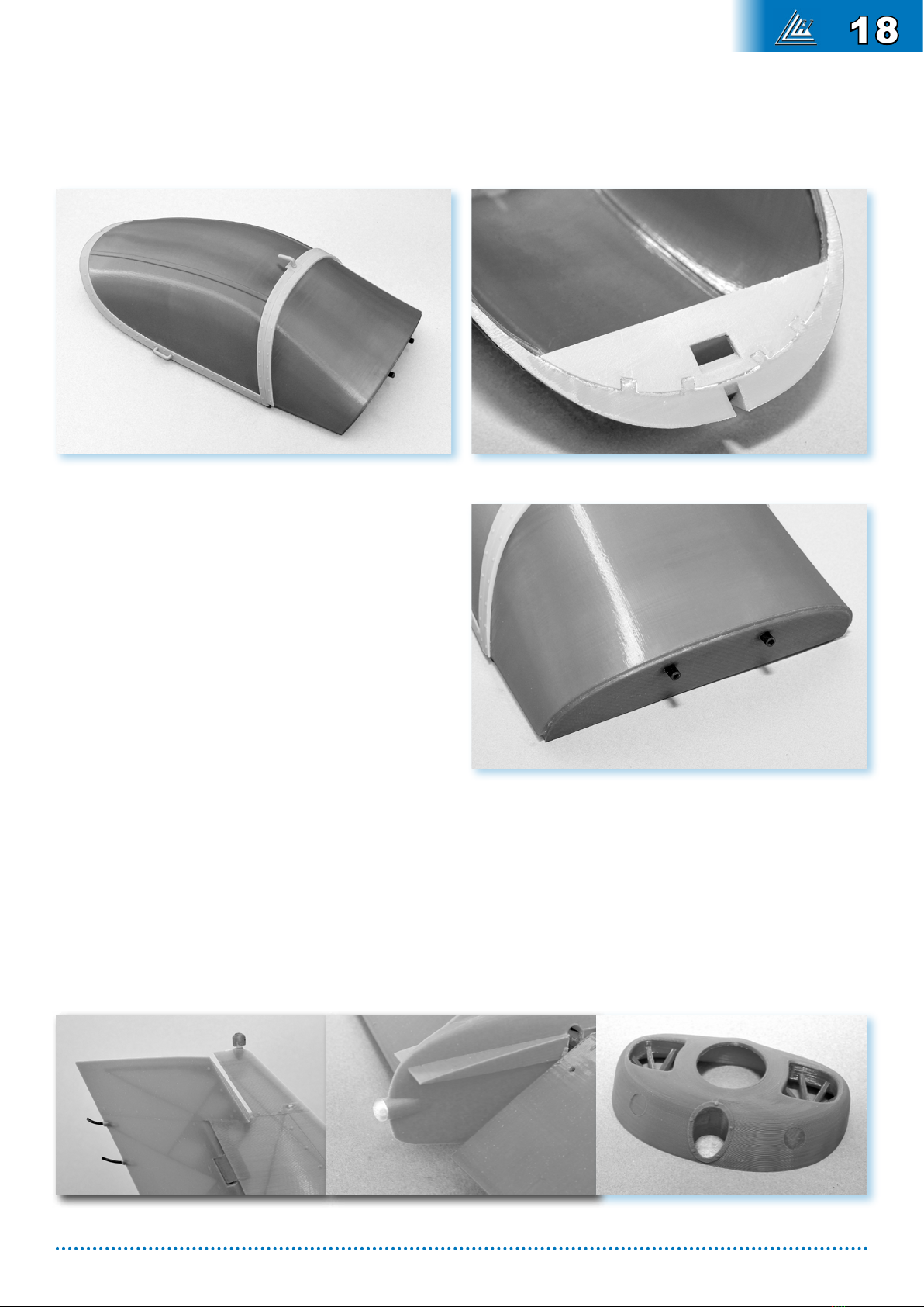
CA glue the strip canopyD to the canopy
canopyB.
CA glue the two half handles canopyG
together then in the upper hole of the canopy
hoop.
Prepare two 4 mm x 16 mm carbon ber tubes.
CA glue the tubes in the front holes of
canopyF leaving them
protrude about 7 mm.
CA glue the rear plate canopyE
to the strip canopyD.
Install the canopy on the fuselage. Depending on the quality of the mounting, it may be necessary
to adjust the locking notch on the canopy back plate canopyE for the locking to work eortlessly.
Glue the rudder light (sf260_light1.stl) to the top of the rudder.
Glue the rear light (sf260_light2.stl) to the fuselage.
Glue the headlight (sf260_light3.stl) in the nose of the plane.
18
FLAPS CONTROL
EPOXY glue the aps control levers to the 2 mm
piano wire axis.
Maintaining the aps in raised position, the levers
must be oriented upwardly, perpendicular to the
longitudinal axis of the aircraft.
The right and left levers must have exactly the
same orientatio.
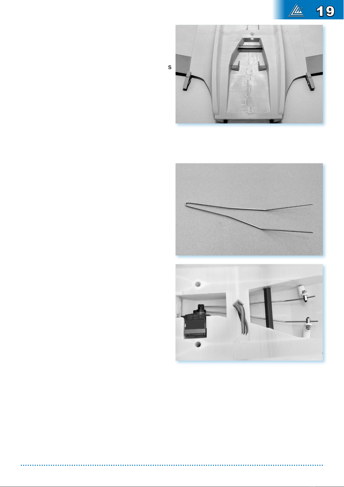
Mark the center of a 1.5 mm diameter piano
wire about 28 cm in length.
Make a 90° bend, followed by a 3 mm dish
and a second 90° bend to obtain a U shape.
With this fork at, slightly bend each branch a
few degrees upwards to approximately 9 cm
from the U.
Insert the piano wire in the aps servo arm
(servo arm length 10 mm).
Mount the servo on the aps servo, face down,
with an angle of about 5° forward.
Fix the servo in its housing, by passing the
piano wire under the carbon reinforcement,
the cable of the servo must lead to the center
hole of the wing.
Adjust the piano string if necessary so that it does
not touch the carbon reinforcement and so that
each branch points correctly towards the corres-
ponding lever.
ALLOW THE EPOXY GLUE TO DRY COMPLETELY BEFORE HANDLING
Connect the piano wire to the levers using dominoes.
The two aps must have the same angle whatever the position of the servo.
19

Install the landing gear mount in the fuselage
with four M3 x 10 mm.
Install the steering servo.
Attaching the servo is tricky due to the lack of
space: use a Phillips head using a pair of pliers
to tighten the screws.
Insert the four M3 nuts in the landing gear
mount.
The four M3 nuts may already be inserted in the
motor mount.
If the nuts do not hold securely in place, add a
drop of CA glue.
FRONT LANDING GEAR
20
Route the servo cables through their respective
tunnels and set up the aileron servos.
If both servos are connected to the same receiver
channel, solder or connect the Y connector.
The cables must run along the landing gear me-
chanisms, the wheel housings and lead about
10 cm into the center of the wing.
Install the 10 mm long servo arms.
Screw the servos in place.
Cut and stick 4 double-sided scotch pads to the
4 corners of the ailerons servos covers and put
them in place.
Fit the aileron linkages according to the usual
methods.
AILERONS CONTROL
Table of contents


