Creator CR-V1013 User manual
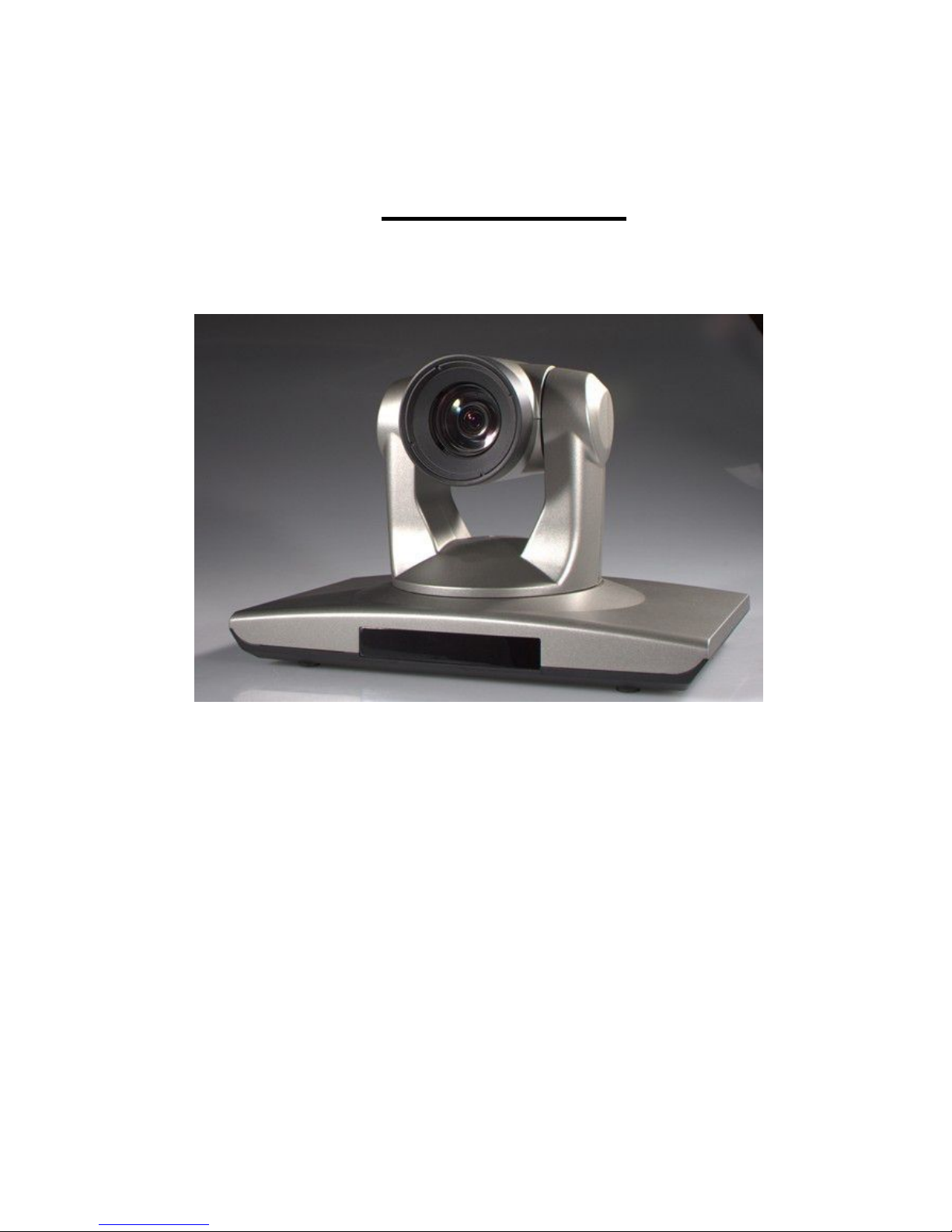
HD Color Video Camera
User Manual

1
Preface:
Thanks for using our HD color video conference camera.
This manual introduces the function installation and operation of
the HD camera. Prior to installation and usage, please read the
manual thoroughly.
Warning
This product can be only used in specified range in order to avoid any
damage or danger.
Don’t expose the camera to rain or moisture place.
Don’t remove the cover to reduce the risk of electric shock. Refer
servicing to qualified personnel.
Never operate the camera under unqualified temperature, humidity
and power supply.
Only use the replacement parts recommended by us.
Please use the soft cloth to clean the camera. Use neuter cleanser if
bad smeared .No uses the strong or cleanser avoiding scuffing.
Be careful or moving; never press the drive parts heavily avoiding
camera trouble.
Notes
Electromagnetic fields at the specific frequency may affect the image
quality.

2
【Contents】
Notes ………………………………………… ………………..
Accessories …………………………………………………….
Fast Installation…………………………………………………
Camera Highlights………………………………………………
Camera specifications………………………………………….
Camera interface explanation…………………………………
Remote Controller explanation…………………………………
Usage of IR remote controller …………………………………
VISCA RS-232 pin specs……………………………………….
Series COM Control …………………………………………….
Menu Setting……………………………………………………...
Maintenance and Trouble Shooting…………………………….
3
Notes
Electric Safety
Installation and operation must accord with electric safety standard
Caution to transport
Avoid stress, vibration and soakage in transport, storage and installation.
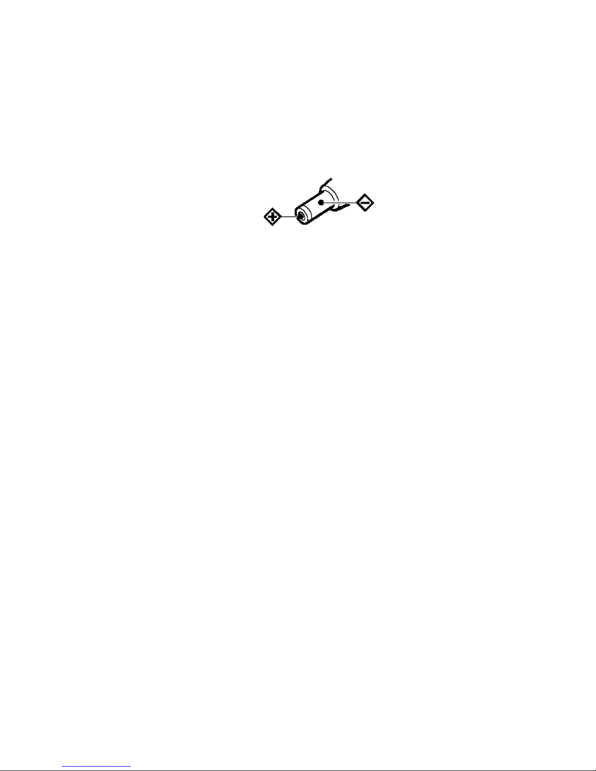
Polarity of power supply
The power supply of the product is +12V, the max electrical current is 2.5A .polarity of the
power supply drawing.
Careful of installation
Never move the camera by seizing the camera head. Don’t rotate camera head by hand;
otherwise, mechanical trouble will occur.
This series item must put on the smooth desk or platform, and it can not be installed
slantways.
If the camera is installed on TV or computer, the base can be fixed by three double-sided
adhesive trays.
Don’t apply in corrosive liquid, gas or solid environment to avoid the cover which is made up
of organic material.
To make sure no obstacle in rotation range.
Never power on before installation is not completed.
Don’t dispatch discretionarily
We are not responsible for any unauthorized modification or dismantling.
Attention: Electromagnetic filed under certain rate may affect camera image!
4
Supplied Accessories
When you unpack, check that all the supplied accessories are included:
Camera …………………………1
Power adaptor …………………1
Power cable…………………….1
RS232 cable……………………1
Remote controller………………1
User manual ……………………1
Double-side glue shim ………..4
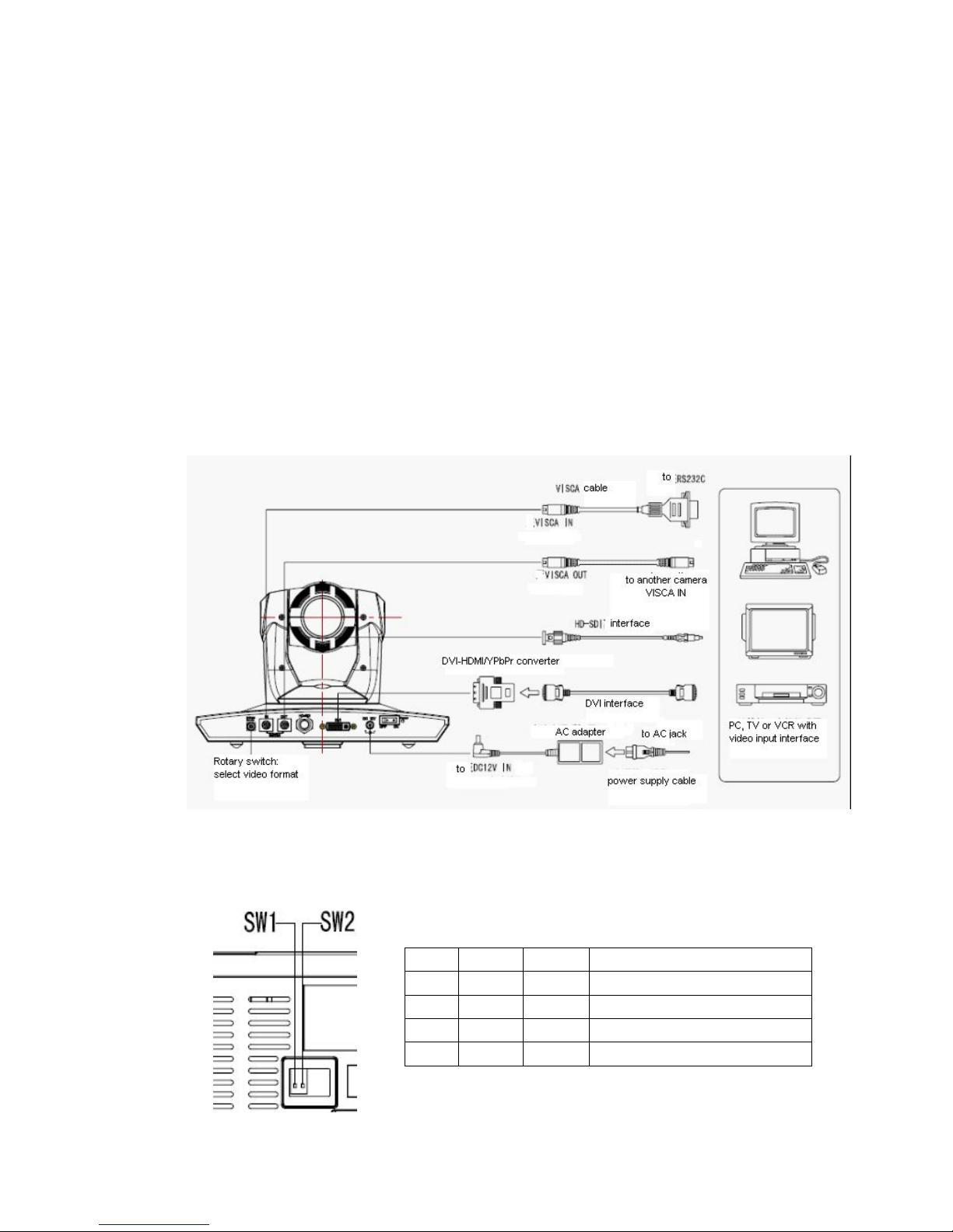
Fast Installation
1. Please check the connection before turn on.
2. Bottom Dial Switch Setting
Two DIP switch set to be OFF, which is normal working mode
SW2-2
SW2-1
Explanation
1
ON
OFF
Undefined
2
OFF
OFF
Updating mode
3
OFF
ON
Debugging mode
4
ON
ON
Working mode
5
3. The Rotary Switch Setting
The video format setting selections
Note: Please restart the camera after shift the video format
4. When Power supply switch is “on”, the indicator light is open (red color)
5. Camera initializes after powered on, the indicating lights on front panel will start flicker by
the order of Red - Yellow- Green : Rotate Pan to the left limit, rotate tilt to the down limit; Then
rotate to the middle of both pan and tilt, the motor stops. Camera lens initializes until the
indicating light become green. Initialization finishes. (Note: If the users do not operate the
camera in 12 seconds, the camera will move to the preset position No.0 or No.1 if saved 0 or
1 preset)
Switch Setting
0
1080P60
1
1080P50
2
1080I60
3
1080I50
4
720P60
5
720P50
6
1080P30
7
1080P25
8
--------
9
--------
A
--------
B
--------
C
--------
D
--------
E
--------
F
Display as the video format set by the menu
RESET
==============
SYSTEM. RESET NO
CAM.RESET NO
PT. RESET NO
ALL. RESET NO
BACK/MENU

6
6. Restore default setting: enter into the OSD menu by press the menu key of remote
controller, select 【Restore Default】, moving the left/right key to press 【Yes】 ,then confirm
by 【HOME】key .
7. Camera Standby: Press the 【Standby】key on the remoter, camera pan tilt will rotate to
the down limit, and then rotate to the right limit to be standby. The working indicates light turn off
and flick as red light once every 20 seconds. If need to wake up the camera, user need to press
again the 【Standby】key and camera will start and run self-checking again.
Camera highlights
1. Camera support both Chinese and English menu which is convenient for using.
2. Multiple and completed HD interfaces; Provide the DVI interface (including YPbPr, HDMI
and VGA signal) and HD-SDI interface.
3. IR remote controller signal transparent transmission function: camera can receive both its
own remote controller signal and the controller signal of terminal equipment by converting to
serial signal then executing. Thus, the terminals can be working in the background.
Camera Specifications:
1. Video format : 1080P60/50, 1080P30/25, 1080I60/50, 720P60/50 (S)
1080P30/25, 1080I60/50, 720P60/50 (M)
720P60/50 (C)
2. Output Interface : DVI(YPbPr, HDMI, VGA), HD-SDI, CVBS(optional)
3. Image Sensor: 1/2.8 type CMOS, 2.07million effective pixels and 2.74 million total pixels.
4. Lens: 4.7mm ~ 84.6 mm,F1.6 - 2.8, angle of view : 55.2°- 3.2°.
5. The Rotation : ±170°for pan rotation and -30°~ +90°for tilt rotation
Support in-ceiling installation.
6. The Control speed: 0.1°-180°/sec for pan rotation, 0.1°-80°/sec for tilt rotation .
7. Preset position No.: 10 preset position with precision error less than 0.2°.
And it can reach to 128 presets position by COM command.
8. Support auto/manual/indoor/outdoor/auto key-control/auto-tracking white balance;
Auto/manual exposure (Iris, Shuttle) and auto/manual/One-Push focus.
9. Support WDR technical: performance ≥100dB, anti-flicker.
10. Control Signal interface: 8 pin mini DIN,RS232,VISCA/Pelco-D/Pelco-P
11. Power interface: HEC3800 power jack, Power supply adapter: DC12V/2.5A.
12. Maximum consumption 12W
13. Working temperature: -5℃to +45℃
14. Storage temperature:-20℃to +60℃
15. Weight 1.3kg
7
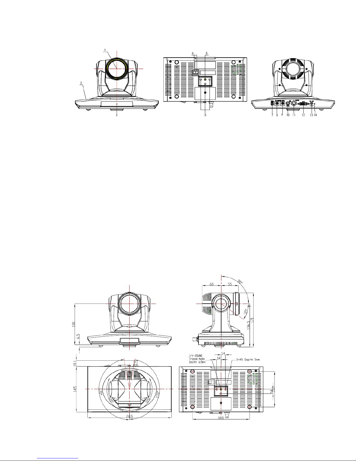
Camera Interface Explanation
1 - Camera lens
2 - Camera base
3 - Working status indicator light (red)
4 - Bottom dial Switch
5 - Tripod screw hole
6 - Installation Orientation Hole
7 - Rotary Switch: video format optional
8 - RS232 controller serial interface (input)
9 - RS232 controller serial interface (output)
10 - CVBS interface (optional)
11 - HD-SDI interface
12 - DVI-I interface(including YPbPr, HDMI and VGA interface)
13 - DC12V Input Power Supply Jack
14 - Power indicator light (red)

8
Remote Controller:
Definition of IR controller
0、Standby key
After press the standby key, the camera will step into
standby mode. Press again, the camera will open
again. (Note: Standby mode power consumption is
about half of the normal mode)
1、Number key
Setting or Running presets
2、* key
Key combination use
3. Set preset key:
Set preset:Preserve a preset
Set preset key + 0-9 number key :Set a preset
corresponding to the number.
Clear preset key:
Clear preset key + 0-9 number key: Clear the relative
preset
or:#+#+#:Clear all the presets
4、BLC control key
Black Light compensation ON/ OFF:Not supported by
the camera
5、Focus control key
【Auto Focus】Enter into auto focus model
Press 【Manual Focus】key to switch to manual focus, the focus can be adjusted by pressing
【Focus+】or【Focus-】
6、Camera address selection
Camera address selection (Note: current version only supports No.1 address)
7、# key
Key combination use
8、pan/tilt control key
Press key :Up
Press key :Down
Press key :Left
Press key:Right
“HOME” key: Return to the middle position

9
9、Menu setting
Open or close the OSD menu
10、Zoom Control key
zoom+:lens near
zoom-:lens far
11、Controlling camera address selection
【*】+【#】+【F1】:the 1st camera address
【*】+【#】+【F2】:the 2nd camera address
【*】+【#】+【F3】:the 3rd camera address
【*】+【#】+【F4】:the 4th camera address
IR Remote Control
When the camera is working, users can control the pan/tilt/zoom, setting and taking preset
positions via remote controller.
Instruction:
1. In this instruction, “press the key” means a click other than a long-press, and a special note
will be given if a long-press for more than one second is required.
2. When a key-combination is required, do it in sequence. For example, “+#+F1”means
press“*”first and then press“#” and press“F1”at last.
1. Pan/Tilt Control
Up: press
Down: press
Left: press
Right: press
Back to middle position:press“HOME”
Press and hold the up/down/left/right key, the pan/tilt will keep running, from slow to fast, until
it run to the endpoint; The pan/tilt running stops as soon as the key is released.

10
2. Zoom Operation
ZOOM OUT: press “ZOOM “key
ZOOM IN: press “ZOOM ” key
Press and hold the key, the camera will keep zooming in or zooming out and stops as soon as
the key is released.
3、Focus Control
Focus (far):Press”focus+” key (only work in manual focus mode)
Focus (near):Press “focus-“key (only work in manual focus mode)
Auto Focus: Press "auto"
Manual Focus: Press "manual"
Press and hold the key, the action of focus continues and stops as soon as the key is
released.
4、BLC Setting
BLC ON / OFF: Not supported
5、Presets setting

11
1、Preset setting : To set a preset position, the users should press the “SET PRESET” key first
and then press the number key 0-9 to set a relative preset, 10 preset positions in total are
available.
2、Preset clearing : to clear a preset position, the user can press the “CLEAR PRESET” key
first and then press the number key 0-9 to clear the relative preset;
Note: press the“#” key three times continually to cancel all the presets.
6、Preset locating
Press a number key 0-9 directly to run a relative preset.
Note: Action in vain if a relative preset position is not exists.
7、Camera Address Setting
Select the camera you want to control by press the number key
8、Camera Remote Controller Address Setting
【*】+【#】+【F1】:Address No.1
【*】+【#】+【F2】:Address No. 2
【*】+【#】+【F3】:Address No. 3
【*】+【#】+【F4】:Address No. 4
12
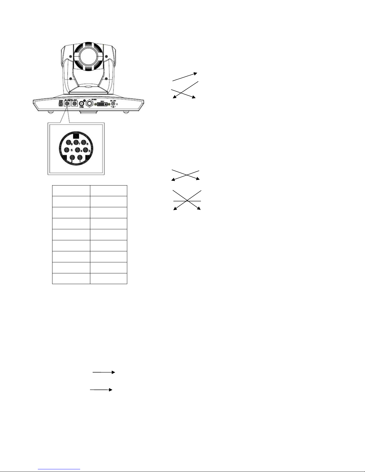
RS-232C Interface (Pin Specs)
Camera Windows DB-9
1.DTR 1.CD
2.DSR 2.RXD
3.TXD1 3.TXD
4.GND 4.DTR
5.RXD1 5.GND
6.RS485-A 6.DSR
7.IR OUT 7.RTS
8.RS485-B 8.CTS
9.RI
Camera Mini DIN
1.DTR 1.DTR
2.DSR 2.DSR
3.TXD 3.TXD
4.GND 4.GND
5.RXD 5.RXD
6.RS485-A 6.GND
7.IR OUT 7.NC
8.RS485-A 8.NC
Camera RS485
1.DTR
2.DSR
3.TXD1
4.GND
5.RXD1
6.RS485-A A
7.IR OUT
8.RS485-B B
9.GND
No.
Function
1
DTR
2
DSR
3
TXD1
4
GND
5
RXD1
6
RS485-A
7
IR OUT
8
RS485-B
13
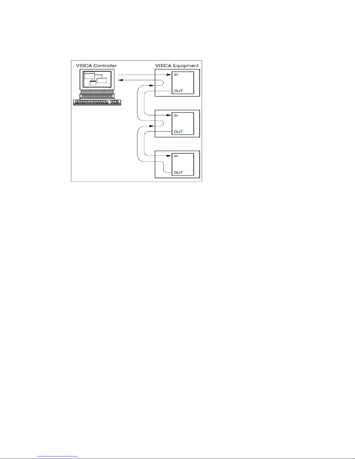
VISCA OUT Function
COM Control
In default working mode, the camera is able to be control via RS232C/RS485 interface
(VISCA IN). The parameters of the RS232C/RS485 COM as following:
Baud Rate :2400/4800/9600/115200 Bit/S
Start bit:1bit;
Data bit: 8bit;
Stop bit: 1bit;
Code: None
Connected to power, the camera runs to left down and back to middle position, with the
farthest zoom rate, auto focus mode and auto iris mode. The camera runs into the preset
No.0 or No.1 if they were saved. After finish this initialization the users can control the
pan/tilt/zoom via COM command.

14
VISCA Protocol
Pat1 . Camera Return Command
Ack/Completion Message
Command Packet
Note
ACK
z0 41 FF
Returned when the command is accepted.
Completion
z0 51 FF
Returned when the command has been executed.
z = Camera Address + 8
Error Messages
Command Packet
Note
Syntax Error
z0 60 02 FF
Returned when the command format is different or when a
command with illegal command parameters is accepted
Command Not Executable
z0 61 41 FF
Returned when a command cannot be executed due to current
conditions. For example, when commands controlling the focus
manually are received during auto focus.
Part 2 Controller Command
Command
Function
Command Packet
Note
AddressSet
Broadcast
88 30 01 FF
Address setting
IF_Clear
Broadcast
88 01 00 01 FF
I/F Clear
CommandCancel
8x 21 FF
CAM_Power
On
8x 01 04 00 02 FF
Power ON/OFF
Off
8x 01 04 00 03 FF
CAM_Zoom
Stop
8x 01 04 07 00 FF
Tele(Standard)
8x 01 04 07 02 FF
Wide(Standard)
8x 01 04 07 03 FF
Tele(Variable)
8x 01 04 07 2p FF
p = 0(low) - 7(high)
Wide(Variable)
8x 01 04 07 3p FF
Direct
8x 01 04 47 0p 0q 0r 0s FF
pqrs: Zoom Position
CAM_Focus
Stop
8x 01 04 08 00 FF
Far(Standard)
8x 01 04 08 02 FF
Near(Standard)
8x 01 04 08 03 FF
Direct
8x 01 04 48 0p 0q 0r 0s FF
pqrs: Focus Position
One Push AF
8x 01 04 18 01 FF
CAM_ZoomFocus
Direct
8x 01 04 47 0p 0q 0r 0s
0t 0u 0v 0w FF
pqrs: Zoom Position
tuvw: Focus Position
CAM_WB
Auto
8x 01 04 35 00 FF
Normal Auto
Indoor
8x 01 04 35 01 FF
Outdoor
8x 01 04 35 02 FF
OnePush
8x 01 04 35 03 FF
Manual
8x 01 04 35 05 FF

15
CAM_RGain
Reset
8x 01 04 03 00 FF
Manual Control of R Gain
Up
8x 01 04 03 02 FF
Down
8x 01 04 03 03 FF
Direct
8x 01 04 43 00 00 0p 0q FF
pq: R Gain
CAM_Bgain
Reset
8x 01 04 04 00 FF
Manual Control of B Gain
Up
8x 01 04 04 02 FF
Down
8x 01 04 04 03 FF
Direct
8x 01 04 44 00 00 0p 0q FF
pq: B Gain
CAM_AE
Full Auto
8x 01 04 39 00 FF
Automatic Exposure mode
Manual
8x 01 04 39 03 FF
Manual Control mode
Shutter priority
8x 01 04 39 0A FF
Shutter Priority Automatic Exposure mode
Iris priority
8x 01 04 39 0B FF
Iris Priority Automatic Exposure mode
Bright
8x 01 04 39 0D FF
Bright mode(Manual control)
CAM_Shutter
Reset
8x 01 04 0A 00 FF
Shutter Setting
Up
8x 01 04 0A 02 FF
Down
8x 01 04 0A 03 FF
Direct
8x 01 04 4A 00 00 0p 0q FF
pq: Shutter Position
CAM_Iris
Reset
8x 01 04 0B 00 FF
Iris Setting
Up
8x 01 04 0B 02 FF
Down
8x 01 04 0B 03 FF
Direct
8x 01 04 4B 00 00 0p 0q FF
pq: Iris Position
CAM_Gain
Reset
8x 01 04 0C 00 FF
Gain Setting
Up
8x 01 04 0C 02 FF
Down
8x 01 04 0C 03 FF
Direct
8x 01 04 0C 00 00 0p 0q FF
pq: Gain Positon
CAM_Bright
Reset
8x 01 04 0D 00 FF
Bright Setting
Up
8x 01 04 0D 02 FF
Down
8x 01 04 0D 03 FF
Direct
8x 01 04 4D 00 00 0p 0q FF
pq: Bright l Positon
CAM_ExpComp
On
8x 01 04 3E 02 FF
Exposure Compensation ON/OFF
Off
8x 01 04 3E 03 FF
Reset
8x 01 04 0E 00 FF
Exposure Compensation Amount Setting
Up
8x 01 04 0E 02 FF
Down
8x 01 04 0E 03 FF
Direct
8x 01 04 4E 00 00 0p 0q FF
pq: ExpComp Position
CAM_Aperture
Reset
8x 01 04 02 00 FF
Aperture Control
Up
8x 01 04 02 02 FF
Down
8x 01 04 02 03 FF
Direct
8x 01 04 42 00 00 0p 0q FF
pq: Aperture Gain
CAM_Memory
Reset
8x 01 04 3F 00 0p FF
p: Memory Number(=0 to 127)
Corresponds to 0 to 9 on the Remote
Commander
Set
8x 01 04 3F 01 0p FF
Recall
8x 01 04 3F 02 0p FF
CAM_LR_Revers
e
On
8x 01 04 61 02 FF
Image Flip Horizontal ON/OFF
Off
8x 01 04 61 03 FF
CAM_PictureFlip
On
8x 01 04 66 02 FF
Image Flip Vertical ON/OFF

16
Off
8x 01 04 66 03 FF
VideoSystem Set
8x 01 06 35 00 0p FF
P: 0~7 Video format
0:1080P60
1:1080P50
2:1080i60
3:1080i50
4:720P60
5:720P50
6:1080P30
7:1080P25
CAM_IDWrite
8x 01 04 22 0p 0q 0r 0s FF
pqrs: Camera ID (=0000 to FFFF)
SYS_Menu
OFF
8x 01 06 06 03 FF
Turn off the menu
IR_Receive
On
8x 01 06 08 02 FF
IR(remote commander)receive ON/OFF
Off
8x 01 06 08 03 FF
On/Off
8x 01 06 08 10 FF
IR_ReceiveReturn
On
8x 01 7D 01 03 00 00 FF
IR(remote commander)receive message via
the VISCA communication ON/OFF
Off
8x 01 7D 01 13 00 00 FF
Pan_tiltDrive
Up
8x 01 06 01 VV WW 03 01 FF
VV: Pan speed 0x01 (low speed) to 0x18
(high speed)
WW: Tilt speed 0x01 (low speed) to 0x14
(high speed)
YYYY: Pan Position(TBD)
ZZZZ: Tilt Position(TBD)
Down
8x 01 06 01 VV WW 03 02 FF
Left
8x 01 06 01 VV WW 01 03 FF
Right
8x 01 06 01 VV WW 02 03 FF
Upleft
8x 01 06 01 VV WW 01 01 FF
Upright
8x 01 06 01 VV WW 02 01 FF
DownLeft
8x 01 06 01 VV WW 01 02 FF
DownRight
8x 01 06 01 VV WW 02 02 FF
Stop
8x 01 06 01 VV WW 03 03 FF
AbsolutePosition
8x 01 06 02 VV WW
0Y 0Y 0Y 0Y 0Z 0Z 0Z 0Z FF
RelativePosition
8x 01 06 03 VV WW
0Y 0Y 0Y 0Y 0Z 0Z 0Z 0Z FF
Home
8x 01 06 04 FF
Reset
8x 01 06 05 FF
Pan-tiltLimitSet
Set
8x 01 06 07 00 0W
0Y 0Y 0Y 0Y 0Z 0Z 0Z 0Z FF
W:1 UpRight 0:DownLeft
YYYY: Pan Limit Position(TBD)
ZZZZ: Tilt Limit Position(TBD)
Clear
8x 01 06 07 01 0W
07 0F 0F 0F 07 0F 0F 0F FF

17
Part3 Command Checking
Command
Command packet
Return packet
Note
CAM_PowerInq
8x 09 04 00 FF
y0 50 02 FF
On
y0 50 03 FF
Off(Standby)
CAM_ZoomPosInq
8x 09 04 47 FF
y0 50 0p 0q 0r 0s FF
pqrs: Zoom Position
CAM_FocusModeInq
8x 09 04 38 FF
y0 50 02 FF
Auto Focus
y0 50 03 FF
Manual Focus
CAM_FocusPosInq
8x 09 04 48 FF
y0 50 0p 0q 0r 0s FF
pqrs: Focus Position
CAM_WBModeInq
8x 09 04 35 FF
y0 50 00 FF
Auto
y0 50 01 FF
Indoor mode
y0 50 02 FF
Outdoor mode
y0 50 03 FF
OnePush mode
y0 50 04 FF
ATW
y0 50 05 FF
Manual
CAM_RGainInq
8x 09 04 43 FF
y0 50 00 00 0p 0q FF
pq: R Gain
CAM_BGainInq
8x 09 04 44 FF
y0 50 00 00 0p 0q FF
pq: B Gain
CAM_AEModeInq
8x 09 04 39 FF
y0 50 00 FF
Full Auto
y0 50 03 FF
Manual
y0 50 0A FF
Shutter priority
y0 50 0B FF
Iris priority
y0 50 0D FF
Bright
CAM_ShutterPosInq
8x 09 04 4A FF
y0 50 00 00 0p 0q FF
pq: Shutter Position
CAM_IrisPosInq
8x 09 04 4B FF
y0 50 00 00 0p 0q FF
pq: Iris Position
CAM_GainPosiInq
8x 09 04 4C FF
y0 50 00 00 0p 0q FF
pq: Gain Position
CAM_ BrightPosiInq
8x 09 04 4D FF
y0 50 00 00 0p 0q FF
pq: Bright Position
CAM_ExpCompModeInq
8x 09 04 3E FF
y0 50 02 FF
On
y0 50 03 FF
Off
CAM_ExpCompPosInq
8x 09 04 4E FF
y0 50 00 00 0p 0q FF
pq: ExpComp Position
CAM_ApertureInq
8x 09 04 42 FF
y0 50 00 00 0p 0q FF
pq: Aperture Gain
CAM_MemoryInq
8x 09 04 3F FF
y0 50pp FF
pp: Memory number last operated.
SYS_MenuModeInq
8x 09 06 06 FF
y0 50 02 FF
On
y0 50 03 FF
Off
CAM_LR_ReverseInq
8x 09 04 61 FF
y0 50 02 FF
On
y0 50 03 FF
Off
CAM_PictureFlipInq
8x 09 04 66 FF
y0 50 02 FF
On
y0 50 03 FF
Off
CAM_IDInq
8x 09 04 22 FF
y0 50 0p 0q 0r 0s FF
pqrs: Camera ID
CAM_VersionInq
8x 09 00 02 FF
y0 50 ab cd
mn pq rs tu vw FF

18
Command
Command packet
Return packet
Note
VideoSystemInq
8x 09 06 23 FF
y0 50 0p FF
P: 0~7 Video format
0:1080P60
1:1080P50
2:1080i60
3:1080i50
4:720P60
5:720P50
6:1080P30
7:1080P25
IR_Receive
8x 09 06 08 FF
y0 50 02 FF
On
y0 50 03 FF
Off
IR_ReceiveReturn
y0 07 7D 01 04 00 FF
Power ON/OFF
y0 07 7D 01 04 07 FF
Zoom tele/wide
y0 07 7D 01 04 38 FF
AF On/Off
y0 07 7D 01 04 33 FF
CAM_Backlight
y0 07 7D 01 04 3F FF
CAM_Memory
y0 07 7D 01 06 01 FF
Pan_tiltDrive
Pan-tiltMaxSpeedInq
8x 09 06 11 FF
y0 50 ww zz FF
ww: Pan Max Speed
zz: Tilt Max Speed
Pan-tiltPosInq
8x 09 06 12 FF
y0 50 0w 0w 0w 0w
0z 0z 0z 0z FF
wwww: Pan Position
zzzz: Tilt Position
Note : 【x】means the camera address you want to control , 【y】=【x + 8】
Pelco-D Protocol
Function
Byte1
Byte2
Byte3
Byte4
Byte5
Byte6
Byte7
Up
0xFF
Address
0x00
0x08
Pan Speed
Tilt Speed
SUM
Down
0xFF
Address
0x00
0x10
Pan Speed
Tilt Speed
SUM
Left
0xFF
Address
0x00
0x04
Pan Speed
Tilt Speed
SUM
Right
0xFF
Address
0x00
0x02
Pan Speed
Tilt Speed
SUM
Upleft
0xFF
Address
0x00
0x0C
Pan Speed
Tilt Speed
SUM
Upright
0xFF
Address
0x00
0x0A
Pan Speed
Tilt Speed
SUM
DownLeft
0xFF
Address
0x00
0x14
Pan Speed
Tilt Speed
SUM
DownRight
0xFF
Address
0x00
0x12
Pan Speed
Tilt Speed
SUM
Zoom In
0xFF
Address
0x00
0x20
0x00
0x00
SUM
Zoom Out
0xFF
Address
0x00
0x40
0x00
0x00
SUM
Focus Far
0xFF
Address
0x00
0x80
0x00
0x00
SUM
Focus Near
0xFF
Address
0x01
0x00
0x00
0x00
SUM
Set Preset
0xFF
Address
0x00
0x03
0x00
Preset ID
SUM
Clear Preset
0xFF
Address
0x00
0x05
0x00
Preset ID
SUM
Call Preset
0xFF
Address
0x00
0x07
0x00
Preset ID
SUM
Query Pan Position
0xFF
Address
0x00
0x51
0x00
0x00
SUM
Query Pan Position Response
0xFF
Address
0x00
0x59
Value High
Byte
Value Low
Byte
SUM

19
Function
Byte1
Byte2
Byte3
Byte4
Byte5
Byte6
Byte7
Query Tilt Position
0xFF
Address
0x00
0x53
0x00
0x00
SUM
Query Tilt Position Response
0xFF
Address
0x00
0x5B
Value High
Byte
Value Low
Byte
SUM
Query Zoom Position
0xFF
Address
0x00
0x55
0x00
0x00
SUM
Query Zoom Position
Response
0xFF
Address
0x00
0x5D
Value High
Byte
Value Low
Byte
SUM
Pelco-P Protocol
Function
Byte1
Byte2
Byte3
Byte4
Byte5
Byte6
Byte7
Byte8
Up
0xA0
Address
0x00
0x08
Pan Speed
Tilt Speed
0xAF
XOR
Down
0xA0
Address
0x00
0x10
Pan Speed
Tilt Speed
0xAF
XOR
Left
0xA0
Address
0x00
0x04
Pan Speed
Tilt Speed
0xAF
XOR
Right
0xA0
Address
0x00
0x02
Pan Speed
Tilt Speed
0xAF
XOR
Upleft
0xA0
Address
0x00
0x0C
Pan Speed
Tilt Speed
0xAF
XOR
Upright
0xA0
Address
0x00
0x0A
Pan Speed
Tilt Speed
0xAF
XOR
DownLeft
0xA0
Address
0x00
0x14
Pan Speed
Tilt Speed
0xAF
XOR
DownRight
0xA0
Address
0x00
0x12
Pan Speed
Tilt Speed
0xAF
XOR
Zoom In
0xA0
Address
0x00
0x20
0x00
0x00
0xAF
XOR
Zoom Out
0xA0
Address
0x00
0x40
0x00
0x00
0xAF
XOR
Focus Far
0xA0
Address
0x00
0x80
0x00
0x00
0xAF
XOR
Focus Near
0xA0
Address
0x01
0x00
0x00
0x00
0xAF
XOR
Set Preset
0xA0
Address
0x00
0x03
0x00
Preset ID
0xAF
XOR
Clear Preset
0xA0
Address
0x00
0x05
0x00
Preset ID
0xAF
XOR
Call Preset
0xA0
Address
0x00
0x07
0x00
Preset ID
0xAF
XOR
Query Pan Position
0xA0
Address
0x00
0x51
0x00
0x00
0xAF
XOR
Query Pan Position
Response
0xA0
Address
0x00
0x59
Value High
Byte
Value Low
Byte
0xAF
XOR
Query Tilt Position
0xA0
Address
0x00
0x53
0x00
0x00
0xAF
XOR
Query Tilt Position
Response
0xA0
Address
0x00
0x5B
Value High
Byte
Value Low
Byte
0xAF
XOR
Query Zoom Position
0xA0
Address
0x00
0x55
0x00
0x00
0xAF
XOR
Query Zoom Position
Response
0xA0
Address
0x00
0x5D
Value High
Byte
Value Low
Byte
0xAF
XOR
Table of contents


