Cree SmartCast KR Series Setup guide

1 of 3 KI086X06R1
INSTALLATION INSTRUCTIONS
KR Series With Cree SmartCast®Technology
LED Architectural Downlight With Emergency Driver
Includes: KR4™ -EB and KR6™ -EB
IMPORTANT SAFEGUARDS
When using electrical equipment, basic safety precautions should always be followed
including the following:
READ AND FOLLOW ALL SAFETY
INSTRUCTIONS
1. To reduce the risk of electrical shock, turn off power supply before installation or
servicing.
2. This luminaire must be installed in accordance with the NEC or your local electrical
code. If you are not familiar with these codes and requirements, consult a qualied
electrician.
3. This luminaire must be supported by main runners or other building structure that
is capable of supporting xture weight.
4. To reduce the risk of electric shock, disconnect both standard and emergency
power supplies and converter connector of the emergency driver before servicing.
5. This luminaire is thermally protected. Do not install insulation within
3 inches (76 mm) of luminaire sides or junction box nor above luminaire in such a
manner as to entrap heat.
6. Blinking LED may indicate xture is too close to insulation.
7. DO NOT mount near gas or electric heaters.
8. Any changes or modications to these devices not explicitly approved by
manufacture could void your authority to operate this equipment.
SAVE THESE INSTRUCTIONS FOR
FUTURE REFERENCE
TO INSTALL:
LUMINAIRE INSTALLATION
NOTE: An Illuminated Test Switch (ITS) with a testplate is shipped
in a separate packaging within the same box as the luminaire to be
installed by customer, see Electrical Connections section for wiring.
This hardware is intended to be mounted seperately from the luminaire
in accordance with the NEC or your local electrical code. Wire and
other necessary hardware must be supplied by customer.
STEP 1:
Mark the intended location of the luminaire and cut appropriate
opening in the ceiling using the chart below:
KR SERIES CUTOUT DIMENSIONS
KR4 4.75 in (12 cm)
KR6 6.5 in (16.5 cm)
STEP 2:
Thread rigid conduit, bar stock, wire or C-channel (supplied by others)
through quick-mount brackets at the sides of the fixture. See Figure 1.
NOTE: For Wall Wash application orientate luminaire as indicated on
Wall Label. See Figure 1.
STEP 3:
Attach mounting means to structure capable of supporting the
luminaires weight.
STEP 4:
Adjust mounting height by loosening adjustment nut, see
Figure 1, and then position bracket so that the bottom of the plaster
ring is flush with the bottom of the opening of the finished ceiling.
STEP 5:
Tighten adjustment nut.
STEP 6:
Remove one of the junction box covers and bring in appropriate power
supply to the junction box using one of the knock-outs. See Figure 2.
1
Wall Label
Quick Mount
Brackets
Adjustment
Nut
Emergency
Driver
KR4™
KR6™
2
Junction Box
Cover
RF Module

2 of 3 KI086X06R1
STEP 7:
Wire luminaire per “Electrical Connections” section and refer to
trim installation sheet to install trim.
NOTE: Luminaire comes with (1) red and (2) yellow/red leads that are
capped off and not used.
STEP 8:
Once electrical connections have been made reinstall junction box
cover that was removed in Step 6.
STEP 9:
Install sensor into ceiling by drilling a 2” hole into the ceiling.
Step 10:
Unscrew the small trim ring near the sensor and place sensor
assembly through the ceiling. See Figure 3.
Step 11:
Secure the sensor assembly by screwing the small trim ring removed
in Step 10 back onto the sensor assembly. Tighten the larger trim ring
above the ceiling until it is tight against the ceiling. See Figure 3.
STEP 12:
Switch the circuit breaker ON.
STEP 13:
The blue LED should repeat a two blink sequence. If the blue LED
does not respond with the two-blink sequence, please follow the
RESET instructions to return the 0-10V Interface to factory defaults.
STEP 14:
Verify the LOAD wiring with the following TEST instructions:
• Press and hold the Test/Reset button for 5 sec then release.
The blue LED should respond with a five-blink sequence. Once
test mode has been entered, LOAD enters State 1. See Table
below.
• Press and hold Test/Reset button for 1 sec then release to
transition to the next state. The sequence repeats after State
3. Please refer to the load table below for your load type.
• To exit test mode at any time, press and hold the Test/Reset
button for 5 sec then release. The five-blink sequence ends
when test mode is exited.
Dimmable Non-Dimmable
State 1 Off Off
State 2 Max light output (10V) On
State 3 Min light output (1V) On
EMERGENCY DRIVER CHECK
NOTE: For short-term testing of the emergency function, the battery
must be charged for at least one hour. The emergency driver must be
charged for at least 24 hours before conducting a long-term test.
STEP 1:
When AC power is applied, the charging indicator light is illuminated,
indicating the battery is being charged. When power fails, the
emergency driver automatically switches to emergency power,
operating the LED array. When AC power is restored, the emergency
driver returns to the charging mode.
STEP 2:
Although no routine maintenance is required to keep the emergency
driver functional, it should be checked periodically to ensure that it is
working. The following schedule is recommended:
• Visually inspect the charging indicator light monthly. It should
be illuminated.
• Test the emergency operation of the fixture at 30-day intervals
for a minimum of 30 seconds. When the test switch is
depressed, the LED array should operate.
• Conduct a 90-minute discharge test once a year. The LED array
should operate for at least 90 minutes.
If the luminaire fails any of these checks, consult service personnel.
REFER ANY SERVICING INDICATED BY THESE CHECKS TO
QUALIFIED PERSONNEL
EMERGENCY DRIVER AND AC DRIVER MUST BE FED FROM THE
SAME BRANCH CIRCUIT.
RESET RF MODULE
NOTE: The Blue LED is located behind the CREE logo on the RF
Module. The CREE logo with illuminate blue when the Blue LED is
active.
STEP 1:
Actuate RESET button through the access hole. Push and hold
until LED on RF Module begins blinking rapidly (approximately 6-7
seconds). See Figure 2 and 4.
STEP 2:
Release for 1 sec.
STEP 3:
Press/Hold RESET button for 0.5 sec. Light will turn off for a few
seconds then go to full bright and the Blue LED on the RF Module
should begin a 2 blink sequence. See Figure 2 and 4.
3
Sensor
Large Trim Ring
Small Trim Ring
Ceiling
4
Test/Reset
Button Inside
RF Module

3 of 3 KI086X06R1
www.lighting.cree.com
© 2016 Cree, Inc. All rights reserved. For informational purposes only. Content is subject to change.
See http://lighting.cree.com/warranty for warranty and specifications. Cree®and SmartCast®are registered trademarks, and
the Cree logo, KR4™, and KR6™ are trademarks of Cree, Inc.
TROUBLESHOOTING:
Out of the box, if the LOAD does not turn on when power is applied:
Perform TEST mode to verify proper functionality of the load type
• If TEST mode fails, check Wiring with power off.
• If wired correctly, check to see if Blue LED is blinking.
• If Blue LED is blinking, then perform a RESET (See RESET
section).
• If Blue LED is on solid or off, call Cree Customer Service.
• If you have done a RESET, and the LOAD is still off, call Cree
Customer Service.
If LOAD is unresponsive use Cree Configuration Tool to verify
configuration.
FCC NOTICE
This device complies with Part 15 of the FCC Rules. Operation is
subject to the following two conditions: (1) this device may not cause
harmful interference, and (2) this device must accept any interference
received, including interference that may cause undesired operation.
Any changes or modifications not expressly approved by the party
responsible for compliance could void the user’s authority to operate
the device.
This device has been tested and found to comply with the limits for
a Class A digital device, pursuant to Part 15 of the FCC Rules. These
limits are designed to provide reasonable protection against harmful
interference when the device is operated in a commercial environment.
This device generates, uses, and can radiate radio frequency energy
and, if not installed and used in accordance with the instruction manual,
may cause harmful interference to radio communications. Operation of
this device in a residential area is likely to cause harmful interference
in which case the user will be required to correct the interference at his
own expense.
In addition, this device complies with ICES-003 of the Industry Canada
(IC) Regulations.
ELECTRICAL CONNECTIONS-
850 AND 1250 LUMEN WITH 120V/277V DRIVER WITH CREE SMARTCAST™ TECHNOLOGY (0-10V)
OR
2000 AND 3000 LUMEN WITH 120/277V DRIVER WITH CREE SMARTCAST™ TECHNOLOGY (0-10V)
NOTE: Luminaire is intended to be wired to a specific voltage.
Make sure that supply voltage matches voltage on electrical
label next to the junction box. Connecting luminaire to voltage
other than that specified on the label may result in luminaire
damage and/or improper luminaire operation. The emergency
driver must be fed from the same branch as the AC Driver.
STEP 1:
Supply connections can be brought to the junction
box using customer supplied conduit.
STEP 2:
Using customer supplied 90°C minimum rated wire connectors,
make the following electrical connections within the junction box.
a. Connect supply ground lead to luminaire
ground, bare/tinned wire.
b. Connect the white/red luminaire lead
to the supply switched hot.
c. Connect supply line conductor to luminaire hot (black).
d. Connect supply neutral conductor to luminaire neutral (white).
STEP 3:
Once ITS is installed make the following electrical
connections within the junction box:
a. Connect ITS violet lead to luminaire’s violet + lead.
b. Connect ITS brown lead to luminaire’s brown - lead.
STEP 4:
Locate the two red leads coming off of the Emergency Driver and
connect them using supplied connector. See Figure 1 on page 1.
HOT
GROUND
BLACK
BARE/TINNED
WHITE
NEUTRAL
SUPPLY WIRING
LUMINAIRE
JUNCTION BOX
VIOLET +
VIOLET
BROWN -
BROWN
ITS
This manual suits for next models
2
Other Cree Flashlight manuals
Popular Flashlight manuals by other brands
Cateye
Cateye AMPP200 manual

Makita
Makita DML803 instruction manual

Yarkiy Luch
Yarkiy Luch PROFESSIONAL BALLISTA 3.0 quick start guide
Foxfury Lighting Solutions
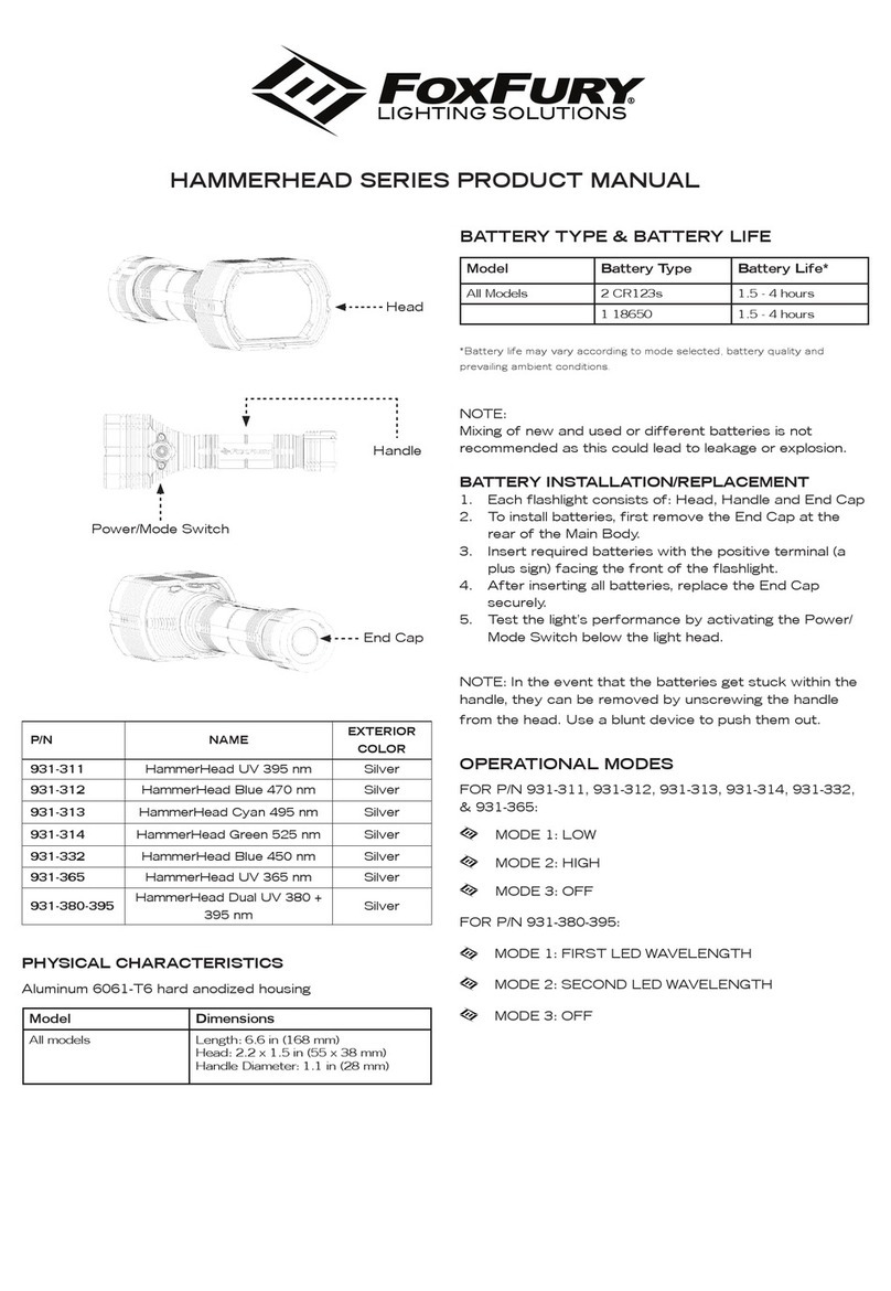
Foxfury Lighting Solutions HAMMERHEAD SERIES product manual
ANSMANN
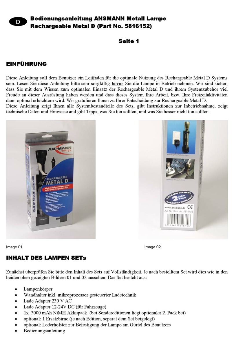
ANSMANN 5816152 operating instructions

Pelican
Pelican M6 2390 LED 3W instruction manual
