Creo Medical 7-EMR-050 User manual

Anything is Possible
with the Right Approach
Instructions
For
Use
IFU
Electrosurgical
Generator
EN
NL
FR
DE
IT
ES
CZ
RO
| Instructions for Use
| Gebruiksaanwijzing
| Mode d’emploi
| Gebrauchsanweisung
| Istruzioni per l’uso
| Instrucciones de Uso
| Návod kpoužití
| Instrucțiuni de utilizare
Proprietary & Confidential - Page 1 of 391 - Uncontrolled if Printed

Proprietary & Confidential - Page 2 of 391 - Uncontrolled if Printed

Instructions for Use - English
Gebruiksaanwijzing - Nederlands
Notice d’utilisation - Français
Gebrauchsanweisung – Deutsch
Istruzioni per l’uso – Italiano
Instrucciones de uso - Español
Návod kpoužití – česky
Instrucțiuni de utilizare - Română
1
47
97
147
196
245
293
339
Proprietary & Confidential - Page 3 of 391 - Uncontrolled if Printed

ENGLISH
1
Electrosurgical Generator
Reference (model): 7-EMR-050. Language: English.
IMPORTANT – For use with Creo Medical accessories and electrosurgical instruments only.
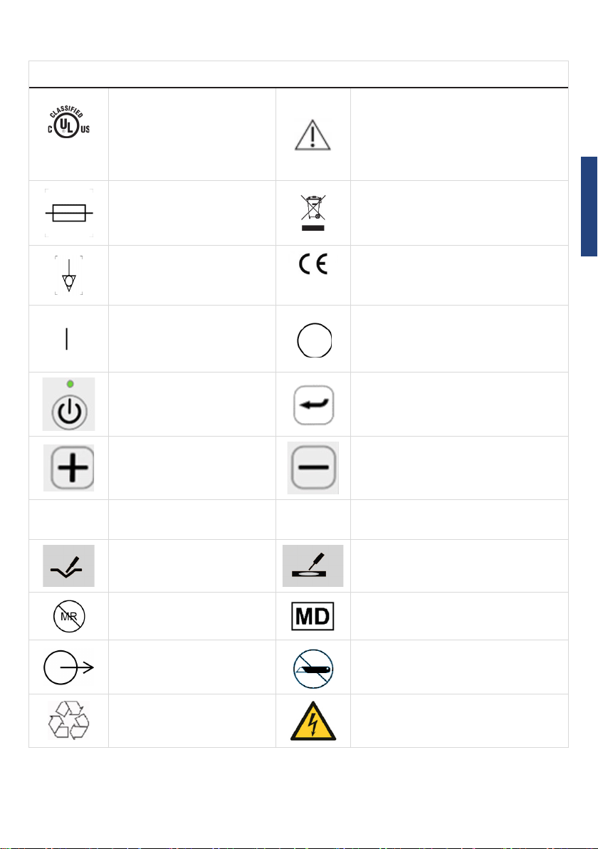
Explanations of symbols, wordings and definitions
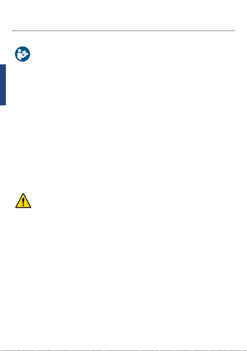
Yellow symbol.
General Warning, when LED
above symbol is lit, refer to
manual.
Do not use if package is damaged
This device generates non-
Do not remove the cover.
Packaging contains one unit
Blue symbol. Read carefully
before use. Keep for future
reference
Instrument can be broken or damaged
if not handled carefully
Applied Part Keep away from sunlight
Manufacturer Keep dry
Date of Manufacture
Country of manufacture
Reference (model) number
Serial number
Proprietary & Confidential - Page 4 of 391 - Uncontrolled if Printed
ENGLISH
2
Explanations of symbols, wordings and definitions
E464226
(applicable only if this is on
the Generator rear panel)
should only be operated by trained
personnel.
Mains inlet power supply
fuses
Do not dispose of the Electrosurgical
Generator in normal waste
2797
CE marking for the Generator
On Symbol located on the
power switch at the rear
of the generator, shown in
at the rear of the generator
The on standby symbol on
the front of the generator
CUT COAG
MR Unsafe
Medical Device
Output from the
Electrosurgical Generator Do Not Use Blade to Open
Recycle Warning, electricity
Proprietary & Confidential - Page 5 of 391 - Uncontrolled if Printed

ENGLISH
3
Explanations of symbols, wordings and definitions
European Community / Union
Transportation, this
symbol appears next to
the symbols indicating
environment limitations
during transportation
Storage, this symbol appears next to
the symbols indicating environment
limitations during storage before and
between uses
RS2
An example of a proprietary
surgical accessory for use
with this Electrosurgical
Generator
Interface
Cable
A proprietary accessory cable that
connects the Generator output socket
to the proximal end of the surgical
accessory
Federal law restricts this device to sale by or on the
order of a physician
Rx Only (USA)
Proprietary & Confidential - Page 6 of 391 - Uncontrolled if Printed

ENGLISH
4
Safety Instrucons
Intended Use
Th
instruments, including the AB1 MicroBlate Flex and NP1 MicroBlate Fine instruments, intended for
Creo Medical instruments, including the Speedboat Instruments
Indicaons and Contraindicaons
that is used with the Electrosurgical Generator. The instruments form the applied parts
to the Electrosurgical enerator.
not intended for use in cardiac procedures.
User Qualicaon
Operators of the Electrosurgical Generator and Instruments must be physicians or medical personnel
techniques. This manual does not explain or discuss clinical electrosurgical procedures.
from Creo Medical.
Proprietary & Confidential - Page 7 of 391 - Uncontrolled if Printed
ENGLISH
5
Safety Instrucons
Instrucons for Use
Generator (Generator). Before use, study this document thoroughly and refer to it whenever
Generator in general, contact Creo Medical.
Warnings
Cauons
Important Safety Warnings
Warnings
-
enced in relevant clinical electrosurgical techniques.
Using the Electrosurgical Generator and Instruments outside their intended use may lead to
Use this Electrosurgical Generator only with appropriate Creo Instruments, Interface Cables
Do not use the Electrosurgical Generator, accessory, or an Instrument if it
appears to be damaged.
Proprietary & Confidential - Page 8 of 391 - Uncontrolled if Printed

ENGLISH
6
Safety Instrucons
If liquid is spilled on the Electrosurgical Generator or the connectors, including the connectors
-
liquid is spilled on the Electrosurgical Generator or the connectors, including the connectors
ensure that:
•
•
electrodes when electrosurgical and physiological equipment is used simultaneously on the
• needle-type monitoring electrodes are not used.
•
-
The Instruments connected to the Electrosurgical Generator and the Electrosurgical Genera-
should be mopped up before the Electrosurgical Generator is used.
this occurs.
way. Servicing of the Electrosurgical Generator must only be performed by Creo Medical per-
Proprietary & Confidential - Page 9 of 391 - Uncontrolled if Printed

ENGLISH
7
Safety Instrucons
electrical shock and will violate the warranty of the Electrosurgical Generator.
In the event of failure of the Electrosurgical Generator, there is a risk of undesirable rise in
the Electrosurgical Generator calibrated and checked for safety once a year.
-
Instrument from the Interface Cable may also terminate treatment and energy delivery.
To avoid risk of electric shock the Electrosurgical Generator must be connected via its AC
USA only: Grounding reliability can only be achieved when the equipment receptacle is
marked “Hospital Grade”.
-
den in the room or building structure.
Proprietary & Confidential - Page 10 of 391 - Uncontrolled if Printed

ENGLISH
8
Safety Instrucons
The Electrosurgical Generator contains no user serviceable parts. To avoid risk of electric
shock and will breach warranty of the Generator.
-
devices and/or electrodes should be excluded from treatment with microwaves and from
-
should be obtained.
Cauon: -
quency power is delivered poses the risk of burns when touching the connector of the Inter-
Cybersecurity
The Electrosurgical Generator is a table-top, non-network connected, mains powered medical
-
Do not use the Electrosurgical Generator and contact customer support if there are signs of
tampering, or for technical assistance.
Proprietary & Confidential - Page 11 of 391 - Uncontrolled if Printed
ENGLISH
9
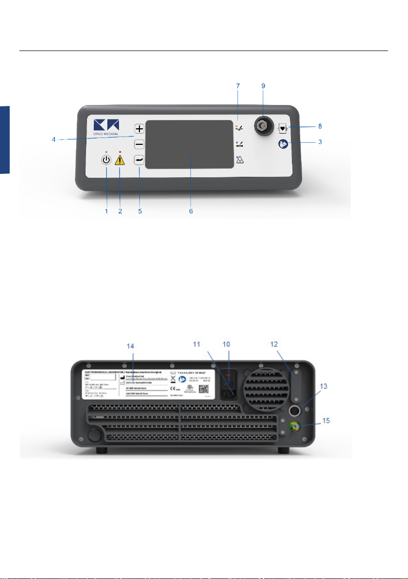
Device Descripon
Front Panel
1.
2. Warning indicator
3. Symbol: Consult Accompanying Documents
4.
5.
6. Display
7. Cut indicator LED (yellow)
8.
applied part
9.
Rear Panel
10.
11. AC inlet
12. Programming port
(service use only)
13.
14. Label with product name and
model number
15.
Proprietary & Confidential - Page 12 of 391 - Uncontrolled if Printed

ENGLISH
10
Device Descripon
The Electrosurgical Generator comprises:
- Output:
• Bipolar RF power at 400 kHz at up to 200 W
• Microwave power at 5.8 GHz up to 62 W
- Front panel interface comprising:
• Membrane-type control keys
• LEDs to indicate status and warnings
:
The Electrosurgical Generator provides output to a single accessory cable capable of delivering two
pad.
Proprietary & Confidential - Page 13 of 391 - Uncontrolled if Printed

ENGLISH
11
Set-up
Warning
The Electrosurgical Generator must always be connected to an AC power supply with a pro-
-
USA only: Grounding reliability can only be achieved when the equipment receptacle is
marked “Hospital Grade”.
Generator may cause a fault to occur if the Electrosurgical Generator is turned ON.
The Electrosurgical Generator weighs approx. 35 lb. (16 kg) and the weight is not evenly dis-
Cauon
The Electrosurgical Generator may cause electrical interference with other equipment. Op-
other equipment. If interference occurs:
• Increase the distance between the Electrosurgical Generator and the suspected interfer-
ing equipment in order to reduce interference.
• Ensure that Electrosurgical Generator cables and connected Instruments are kept as far
away as possible from other equipment cables.
a tripping hazard.
There must be clearance of at least 9 cm (3.5 inches) to the rear of the Electrosurgical Gener-
from the Electrosurgical Generator.
The Electrosurgical Generator is equipped with internal cooling fans. The cooling air intakes
are located towards the front both on the underside and on the on the right-hand side wall
of the Electrosurgical Generator as viewed from the front of the Electrosurgical Generator. Do
not allow these areas to be blocked.
The Electrosurgical Generator does not use a neutral electrode.
Proprietary & Confidential - Page 14 of 391 - Uncontrolled if Printed

ENGLISH
12
Set-up
STEP 1.
use.
STEP 2.
STEP 3.
‘I’ and ‘O’) above the AC inlet (10) for the power supply cord on the Rear Panel is set
to th
below:
STEP 4. Connect the AC power supply cord to the AC inlet (10).
STEP 5.
Connect the AC power supply cord directly to a suitably rated AC wall socket. Do not
STEP 6.
the Electrosurgical Generator.
STEP 7.
STEP 8.
Proprietary & Confidential - Page 15 of 391 - Uncontrolled if Printed

ENGLISH
13
STEP 9.
If needed, the Creo Electrosurgical Generator can be connected to the external grounding system of the
cable designed for this purpose. External grounding removes the hazards presented by low frequency
Proprietary & Confidential - Page 16 of 391 - Uncontrolled if Printed

ENGLISH
14
Normal Use
Warning
-
Turning ON the Electrosurgical Generator
STEP 1.
To turn ON the Electrosurgical Generator, on the Rear Panel push the part of the On /
See picture below
now in Standby Mode.
Proprietary & Confidential - Page 17 of 391 - Uncontrolled if Printed

ENGLISH
15
STEP 2.
to exit from Standby Mode. An audible tone will then be generated from the internal
speaker of the Electrosurgical Generator, the 5 LEDs on the Front Panel will illuminate
Display Screen is working properly.
STEP 3.
selected language.
STEP 4.
ready to proceed” is displayed.
Proprietary & Confidential - Page 18 of 391 - Uncontrolled if Printed

ENGLISH
16
Normal Use
Connecng the Instrument
Warning
Interface Cable.
Ensure that the Interface Cable is securely connected to the Electrosurgical Generator and the
a tripping hazard.
The Interface Cable is required to connect an Instrument for use.
on the Front Panel.
either the Electrosurgical Generator or to the Instrument
Proprietary & Confidential - Page 19 of 391 - Uncontrolled if Printed

ENGLISH
17
Normal Use
Connect the required Instrument to the Interface Cable.
Select and Conrm Connected Instrument
Warning
-
ment.
STEP 1
When an instrument has been
connected the generator will
display the Select Instrument screen
as illustrated.
(the round
to select the connected instrument.
STEP 2
The Generator will then display
This is illustrated to the right when
RS2 was selected from the Select
Instrument screen.
been selected.
screen.
If the wrong instrument has been selected and
is displayed, disconnect the instrument and then reconnect the instrument. The Select
Instrument screen will then be displayed.
Scroll to Confirm Instrument
===
RS2
Proprietary & Confidential - Page 20 of 391 - Uncontrolled if Printed
Other manuals for 7-EMR-050
2
Table of contents
Languages:


