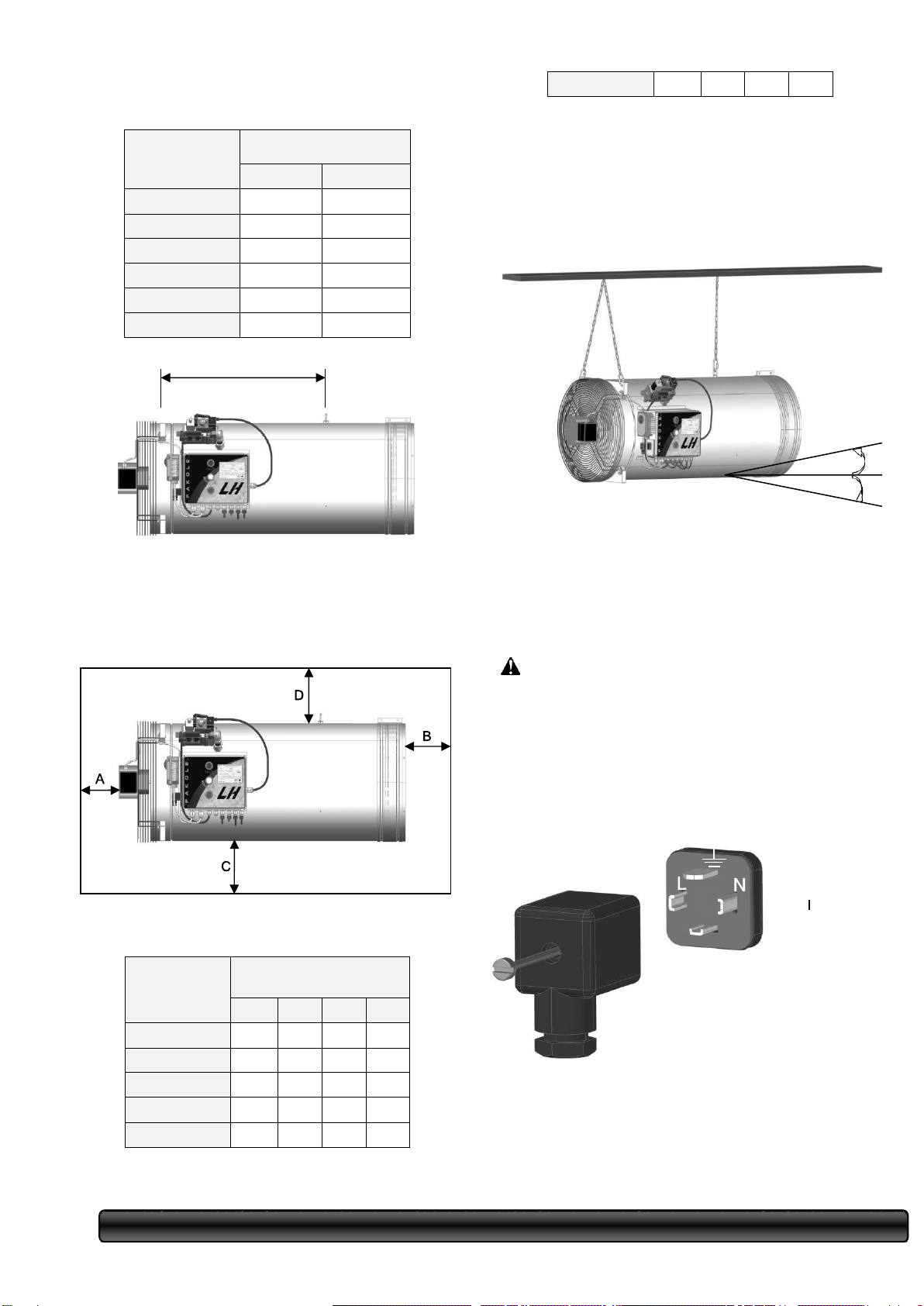
Pakole LH-30 User manual

OPERATING MANUAL GAS HEAT
GENERATOR
OPERATING ON NATURAL AND
LIQUEFIED GAS
Industrial heating equipment
IMPORTANT: Before putting into operation the device , carefully read this
manual.
Failure by the consumer to comply with the rules of operation of the
heating device set forth in this manual may lead to undesirable
consequences. Keep this manual for answers to questions that arise
during operation .
GENERAL SAFETY REQUIREMENTS
Neglect of the requirements set forth in this guide can lead to such
consequences as: material damage and serious harm to human health,
namely: fire, explosion, suffocation, carbon monoxide poisoning,
electric shock, which can lead to death.
Operation and installation of the device is allowed only after careful
reading of the operating manual and strict compliance with the requirements
specified in it.
page 1 of 13

page. 1
from 13
CONTENT
Safety...............................................information2
..............................................................................
Unpacking......................................... the device3
..............................................................................
..............................................................................
General .........................................characteristics
.................................................................... of the
................................................................ device3
..............................................................................
Device............................................................ and
............................................................... principle
......................................................... of operation
...................................................... of the device4
..............................................................................
..............................................................................
Installation.................................... of the device5
..............................................................................
..............................................................................
Gas connection5 ...............................................
Providing air supply5........................................
Installation of the device6.................................
Device ......................................... suspension6
Connecting the power supply7........................
............................................ Instrument control7
.............................................................................
.............................................................................
................................................ Commissioning8
.............................................................................
.............................................................................
Instrument ............................................. start8
Failures (RESET) ...........................................8
Disabling...................................... the device9
.........................................................................
.........................................................................
Possible malfunctions and methods
their elimination9 ..........................................
Storage9........................................................
maintenance10............................................
Prevention10……………………………………
Service10………………………………………..
Specifications11............................................
Applications12………………………………….
Appendix No112...........................................
Appendix No212..........................................
Warranty13 ..................................................

page. 1
from 13
SAFETY INFORMATION
WARNING
The device is designed for air heating of industrial
agricultural premises
in
accordance with the regulatory requirements Msz EN
525:2001. The device is designed for temporary or
permanent heating of industrial and agricultural
facilities. With proper operation, this device is safe and
energy-saving. The combustion products formed during
the combustion process, mixing with the flow of hot air,
fall into the heated room.
Due to the fact that it is impossible to foresee all
possible applications of the device, before installing it ,
it is necessary to coordinate the possibility of its use
with the local fire safety department.
The gas connection must comply with the current
requirements, regulations, in accordance with which
work must be carried out on the supply of natural gas,
and in the case of liquefied gas compliance with storage
rules.
Carbon monoxide poisoning : The primary symptoms of
poisoning are very similar to a cold, in addition, they can
cause headache, dizziness, nausea. If you feel the
above symptoms , you must immediately leave the
room, go out into the fresh air.
Propane or P/B gas: Propane and P/B gas are odorless,
aromatic substances are added to it for the timely
detection of its leakage. However, even without feeling
the characteristic smell, gas leakage and its presence in
the surrounding air are possible.
Make sure that you have read and understood all the
warnings, compliance with which will make it safe and
optimal operation of the device:
-
When installing and operating , adhere to the current
requirements and rules in relation to gas-using
equipment.
-
The connection of the device to the power supply
should be carried out in strict accordance with the
Operating Manual .
-
For your safety, check that the grounding is correct.
-
When operating the device in a closed room, provide
supply ventilation.
-
Use the device only in well-ventilated areas. The
amount of air required for combustion and ventilation is
indicated in Appendix No. 1 to this manual.
-
Protect the device from the following possible
influences: wind, strong water jet, rain or dripping water.
-
Do not use the device in an open space.
-
It is strictly FORBIDDEN to use the device in
rooms intended for sleeping or long-term stay of people.
-
Comply with the requirements of safe distance for
placing the device in relation to flammable materials,
such as: fuel, gasoline, solvent, etc. flammable vapors,
liquids.
-
Do not use the device in heavily dusty rooms, as
dust also ignites.
-
When operating, take into account that the device is
equipped with an individual thermostat and, in
accordance with the specified parameters, can start
starting at any time
-
Before starting the device, always conduct a visual
inspection, if any damage is detected, do not turn on
the device.
-
Do not place a device operating on liquefied gas in
semi-basement and basement rooms, since the specific
gravity of liquefied gas is heavier than air and in case
of possible leakage tends to lower rooms.
-
Use only manufacturer-recommended flexible
hoses and gearboxes.
-
Before each start-up, check the integrity of the gas
connection, if you find damage, fractures on the flexible
hose, replace it with a slag recommended by the
manufacturer.
-
Install or suspend the device only on such structures
that, regardless of the heating of the device, remain
stable.
-
Do not allow children and animals to the working
device.
-
If you plan not to use the device for a long time, be
sure to turn off the power supply and gas connection.
-
Never block the air intake and blowout holes.
-
Do not move or repair the device during operation, as
well as the turned off device that is under voltage.
ATTENTION : Operation of the
device is prohibited in domestic premises.
WARNING: Explosive hazard.
Strictly adhere to the
requirements for placing the device in a heated room
in
relation to flammable materials (building structures,
paper, cardboard).
Never use the device in rooms
gassed with vapors of gasoline, solvent or other
chemical compounds, as well as in heavily dusty rooms.

page 12.
-
Do not use air duct elements at the inlet or outlet of
the device that are not recommended by the
manufacturer.
-
When replacing spare parts, use only original spare
parts recommended by the manufacturer and do not
use parts with
similar parameters, this can lead to serious damage to
the device.
Always use only recommended and manufacturer-
approved gearboxes, the minimum pressure of which
can not be lower than 30 mbar and not higher than 60
mbar.
UNPACKING THE DEVICE
Unscrew the screw at the end of the locking rod,
then remove the rod and the locking plate.
GENERAL
CHARACTERISTICS OF THE
DEVICE
Hot air blow hole
Open it Box Device иRemove from Her parts Part then
Remove Protective covering from the device (e.g.
polystyrene or etc.)
-
Remove the protective cap of the gas
connection immediately before connecting
the gas after the installation work is
completed.
-
Check if the device is not
affected during transportation.
-
If you find any damage, report it to the vendor.
-
After unpacking the instrument, remove the
airflow regulator and fan locking rod.
-
Gas connection kit (flexible hose, filter, faucet)
Rice. 1 External type of device
Combined solenoid valve
(double locking)
Gas
connection
Gas pressure sensor
Failed Fan
(On/Off)
Heating (On/Off)
Heat regulator
Connecting the power supply
Rice. Appearance of the control panel
Stainless steel housing
Suspended points
Protective grille
Fan
Control
Panel

page 12.
DESIGN AND PRINCIPLE
WORK DEVICE
Gas supply system : For the safe operation of the
device, the network gas pressure must be at least 30
mbar, but not exceed 60 mbar.
After connecting the gas connection kit to the
network and the device, open the gas tap, after
which the gas will begin to be supplied through the
gas filter, solenoid valve, nozzles into the
combustion chamber.
Air supply system : The motor will turn the fan
blades, which in turn will supply the necessary air
flow inside the device. The air flow created in this
way, dragging with it the heat created during the
combustion of the gas-air mixture and the
combustion products formed during this process, is
fed into the heated zone.
Ignition system : The control electronics in
accordance with the specified temperature
parameters give a high-voltage electrical signal to
the spark plug, which under this influence begins to
spark thereby igniting the gas-air mixture.
Safety and control system: For your safety, the
device is equipped with three sensors
-
ionization flame control
-
Airflow
sensor
-
overheating sensor
In some countries, such as Ukraine, Russia, etc.,
according to the requirements, it is necessary to
install a fourth sensor
-
a minimum gas pressure
sensor.
Airflow sensor
Rice. 3 Burner + safety elements.
In connection with the constant work on improving
the device, increasing its reliability and quality,
changes may be made to the design of the device
that are not reflected in this documentation.
INSTALLATION OF THE DEVICE
Gas supply system
Combined electromagnetic valve
ionization flame controller
combustion air, heating air
Rice. 2 The device in the section + the principle of
operation
The gearbox is installed separately in front of each
device or one common gearbox on the central gas
supply pipe. A filter must be installed before each device
to prevent blockage of the solenoid valve due to
possible contamination from gas pipelines (despite the
fact that the solenoid valve is blocked ) to purge them).
Connection to the main gas pipeline is carried out top or
side, as the connection at the bottom will be serve
Collection Pollution A what Can influence on Normal
Work Device.
overheating
sensor
sensor
overheating
sensor
Fuse controller and flame control
ATTENTION: Heat generators type LH-... can
work only with the gas
specified in the instruction manual.
When operating the device on natural gas, the
pressure of the network gas is 30 mbar.
When operating the device on liquefied gas, the gas
pressure is 50 mbar.
The maximum gas pressure is 60 mbar.
ATTENTION: If the pressure in the gas network
exceeds 60 mbar. - the use of
a pressure reducer
is
mandatory
.

danger of carbon monoxide poisoning. Before
starting the device, ventilate the room.
Determination of the required
amount of fresh/ventilation air
In accordance with the existing standards, the
calculation of the required amount of fresh / ventilation
air is carried out:
Rice. 4 Correct/incorrect connection to the gas
pipeline
It is necessary to take into account the thermal
expansion of the device, so the connection of the device
to the gas pipeline is carried out with a flexible hose.
Flexible hose
(
L
Q
C
Where is
T
10
3
) 110 103
N
Q
10
3
v
100 100
Q
1130
L
(
N
1,13
C
v
T
)
i.e.
is installed so as to provide an extension of at least 100
mm.
The flexible hose must be connected
without kinks!
Pakole recommends using the gas connection kit they
supplied, which includes a flexible hose, a filter, a ball
valve. If you want to install a gearbox in front of each
device, it should be installed between the filter and the
flexible hose.
L –room heat loss
Q –(= AV) air exchange m³/h
N –maximum permitted heat output is 86
kJ
/m³
Cv - specific calorific value of air is 1.207 86
kJ
/m³K
Т –temperature difference in Kelvin
110/100 –the value gives a 10% premium for fast
warm-up
103/100 –the value gives a 3% surcharge on the heat loss of the
device body
For an example of the calculation, see the following articles:
See Annex No. 1.
INSTALLATION OF THE DEVICE
Ball tap
Rice. 5 Set of gas connection
you must do the following
-
Before connecting the devices to the gas network
Installation must comply with the current requirements,
rules, in accordance with which work on the installation
of the device must be carried out. Therefore, the
specialist installing the device must comply with all the
rules for the installation of gas equipment.
The specialist installing the device should check the
tightness of the gas connection.
Before installing the device, it is necessary to check the
compliance of local conditions, gas type and pressure
with the factory setting of the device.
carry out thorough cleaning and blowing
Gas pipeline.
-
Check the tightness of the connections. This
procedure must be repeated after each
disconnection / connection to the gas pipeline. D
PROVISION FEED AIR
page 12.
Sealing gasket
Gas filter
Always adhere to the
requirements for a minimum
supply of fresh/ventilation air. If the inflow of
fresh/ventilation air is insufficient,
there may be

page 12.
Rice. 6 Overall dimensions of the device
Power
[kW]
Overall dimensions
(mm)
D
L
30 kW
435
1130
40 kW
435
1130
50 kW
435
1130
60 kW
435
1130
70 kW
435
1130
80 kW
435
1130
Rice. Fig. 7: Distance between suspension mounts
Requirements for distances, safety
and fire protection
:
The distance depends on the
power of the device
Rice. 8 Minimum safety and fire protection distances.
Power
[kW]
Protective distances, mm
A
B
C
D
30 kW
300
1200
500
500
40 kW
300
1350
500
500
50 kW
450
1500
500
500
60 kW
450
1650
500
500
70 kW
450
1800
500
500
DEVICE PENDANT
For Warning Deformation in consequence of Heat
Extensions length Suspension (e.g.chain) must be at
least 400 mm. Attach suspension under Roof or Ceiling
on Reference beams or supports, between pillars or
against the wall. Suspension of the device is performed
with the help of ears, Located on his Housing.
Rice. 8 Device suspension
When suspending, the device is installed horizontally,
the maximum permissible
deviation is +5 / -5 º.
POWER CONNECTION
- the device is connected to the mains through a safe
connector in the control unit (box).
-
How to connect to the network:
By means of a grounded plug or a fixed connection
taking into account the correct phase,
-
max. electric consumption of the device 1,5 A
-
Mains power wire: 3x0.75 MT cable
-
The device is sensitive to phase, so the
connection must be made as indicated in the figure.
L
–
Phase
N
–
Zero
Earth
An electrical diagram of the power supply with Brahma
automation is given in Appendix No. 2.
80 kW
450
1950
500
500
590
+5
-5

page 12.
INSTRUMENT CONTROL
The heat generator type LH is equipped with an
individual thermostat, it is located on the side wall of the
control panel on the side of the discharge fan.
Temperature scale of the thermostat: from 0 to 40 º C.
The automatic mode of operation of the device occurs
by turning on / off the device, which, depending on the
air temperature in the room in relation to the
temperature set on the device, turns on or off.
An external thermostat can also be connected to the
device. For a diagram of the connection of the external
thermostat, see. Appendix No2.
The device can operate in three operating positions :
-
VENTILATION
-
VENTILATION + HEATING
-
HEATING
VENTILATION:
Turning on the power supply of the device, press the
white button on the control panel with the inscription fan,
the device will start the fan, and will work in ventilation
mode, in which the light signal of the white button is
constantly lit. To turn off the ventilation mode, you must
press the white button again.
VENTILATION + HEATING:
Having turned on the power supply of the device, press
the green, then the white button on the control panel, in
this case the ventilation mode is constantly working,
and the heating mode is turned on periodically
depending on the air temperature in the room in relation
to the set on temperature device.
In this position, the light signal should be lit on both
buttons. When you press the white button again , the
ventilation mode is turned off, and the device will
operate in automatic heating mode.
It is possible that when you press the white button
again, the light signal will not go out, this is due to the
fact that the shutdown was made at the time when the
fan was started in heating mode.
HEATING:
After turning on the power supply of the device, press
the green button on the control panel, in this case the
heating mode is constantly running. If only the light
signal of the green button on the thermostat is lit , this
means that the air temperature is in a room higher than
the specified one. This is
will last until the air temperature in the room drops below
the temperature set on the thermostat and the
thermostat starts the heating mode, in which the light
signal of the white button should light up. After reaching
the set temperature in the room, the thermostat turns off
the heating mode, stops the fan and the light signal of
the white button goes out.
COMMISSIONING
Starting the device
If you have selected the above mode of operation of the
device, then press the button or buttons you need and
the device in accordance with this will launch the
program of your choice .
The ignition process starts from 30 seconds. Purge.
during this purge the airflow controller analyzes the
correct operation of the fan and its ability to create the
necessary airflow . if the airflow sensor detects the
correct operation of the fan then after the expiration
30 sec. the electronics will start the spark, at the same
time as the solenoid valve opens, opening the gas
access to the combustion chamber, where the gas-air
mixture is ignited by means of sparking. If the ignition
was successfully performed, the ionization controller
the flame detects the correct pattern of combustion, the
device begins to work and perform its heating functions.
In those countries where the installation of a minimum
gas pressure sensor is mandatory , the start of the
device will occur only if the pressure of the network gas
exceeds the specified minimum. If during the operation
of the device, there is a pressure drop in the network,
the minimum gas pressure sensor will turn it off.
Malfunctions (RESET)
During the operation of the device , malfunctions may
occur, controlled by the safety system of the device.
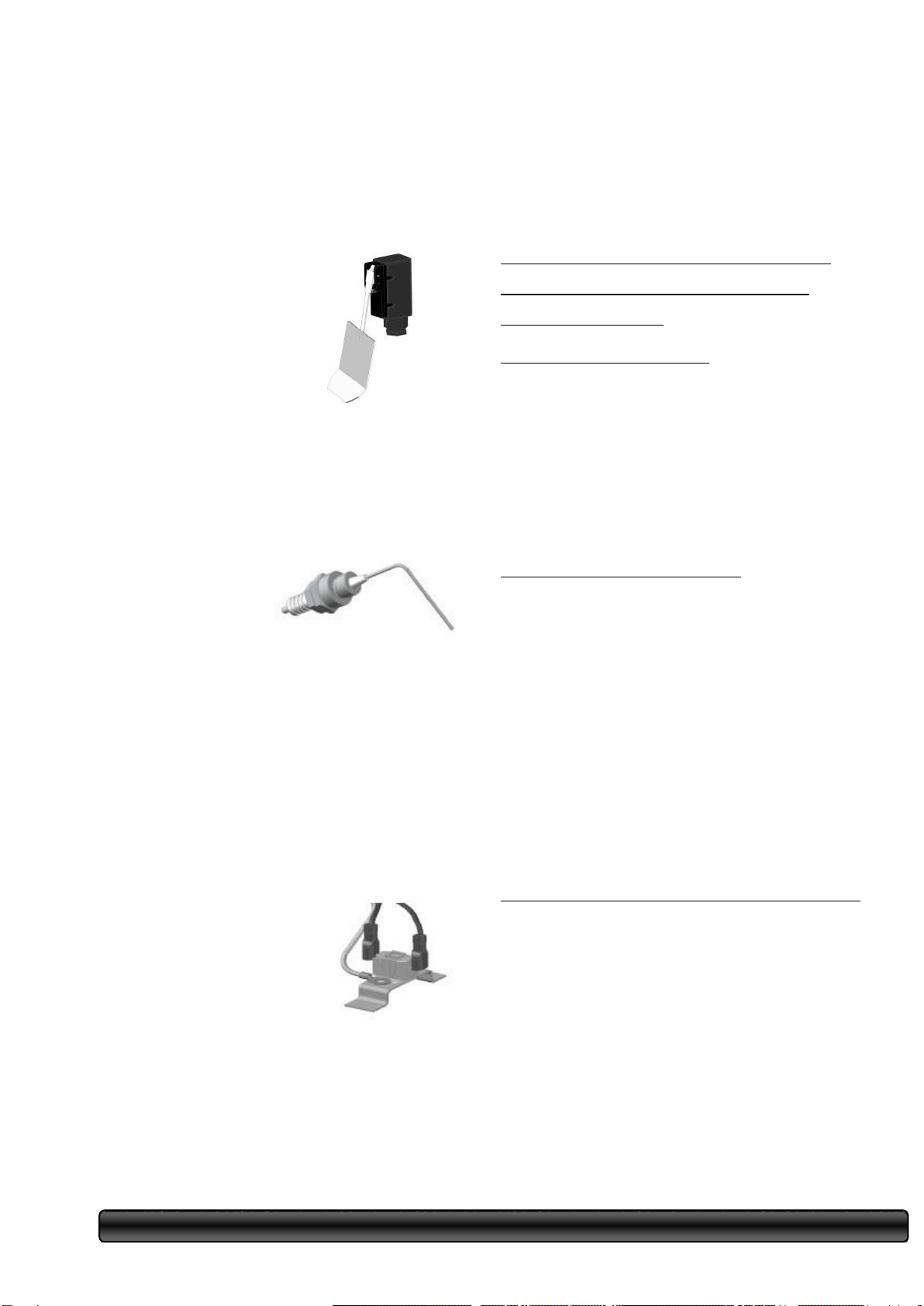
The basic model of the device is equipped with three
controllers:
-
ionization flame controller
-
Airflow sensor
-
overheating sensor
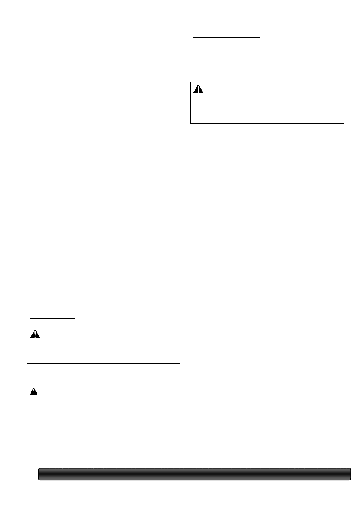
In some countries, such as Ukraine, Russia, etc. a
fourth sensor is required
–
a minimum gas pressure
sensor. The instruments supplied to these countries are
equipped with four sensors.
These sensors independently monitor the correct flow
of the worker

page 12.
The process of the device and, having detected any
malfunction, give a signal to the electronics, which
immediately stops the operation of the device.
Airflow sensor Airflow sensor
analyzes the correct operation
of the fan and its ability
to
create
the necessary airflow, as
well as the operating state
of the
motor,
no barrier of
atmospheric air intake to the
fan. If
the airflow sensor will not switch to the closed position,
the control automation stops the start-up process and
the light signal of the red button (FAILURE) lights up on
the control panel. The failure signal is removed by
pressing the red button, after it is extinguished, the start
attempt is automatically repeated.
Flame ionization control
The ionization control
of the flame is
responsible for the
ignition process,
i.e. the ignition process.
there was a stick
of sparks
during the operation
of the appliance
controls the presence of flames. If for any reason the
flame is extinguished, the controller immediately sends
a signal to the automatic control, which in turn turns off
the device and the light signal lights up on the control
panel. Red button (FAILURE). The fault signal is
removed by pressing the red button. After that, the
attempt is automatically repeated. If the device does not
turn on when you try to start again, contact the service
department.
Overheating
sensor
The overheating sensor is located
under the casing of the device and
its function is to
constantly
monitor the temperature of the
casing. If the temperature of the
casing reaches 134ºС, the
controller immediately sends a
signal to the automatic
control, which in turn turns off the device and the light
signal of the red button (FAILURE) lights up on the
control panel. The failure signal is removed by
pressing the red button and after it is extinguished, the
start attempt is automatically repeated .
Disabling the device
Disconnect the device in the following sequence:
-
Make sure that all buttons on the control panel are
in a depressed state and that no lights are on.
-
Close the gas tap in front of the appliance.
-
Turn off the power supply to the appliance.
POSSIBLE MALFUNCTIONS
AND METHODS OF THEIR
ELIMINATION
The axial fan does not turn on Possible
causes:
-
No power is supplied to the motor
-
The fuse has failed
Troubleshooting
options :
-
Check the power supply
-
Replace the fuse. If the fuse fails, find the cause of
the overvoltage.
No spark between ignition electrodes
Possible causes:
-
No voltage between the ignition unit and the control
electronics
-
Too large spark gap with
ignition electrodes
-
Damaged control automation
Troubleshooting capabilities:
-
Clean the ignition electrodes
-
Check the electrical connection between the ignition
unit and the control electronics
-
Check the spark gap between the ignition electrodes
-
Replace control automation
The device does not work after the first ignition cycle
Possible causes:
-
Gas tap
closed
-
Gas pipeline is aired
-
Inappropriate nozzle pressure
Troubleshooting options :
-
Open the gas tap
-
Blow the gas pipeline

page 12.
-
Check the gas inlet and outlet pressure on the
solenoid valve measuring nozzles
The device does not work after repeatedly trying to start
the ignition cycle
Possible causes:
-
Damaged solenoid valve
-
The electrical connection between
the
igniter
and the
control electronics was interrupted
-
Inappropriate pressure on the injector
-
Improperly performed grounding
Troubleshooting options :
-
Replace the solenoid valve
-
Check the electrical connection between the
igniter and the control electronics
-
Check the gas inlet and outlet pressure on the
solenoid valve measuring nozzles
The gas burner starts, but after a while the flame goes
out
Possible causes:
-
Confused zero and phase wire
-
Inappropriate pressure on the injector
-
Airflow controller returns to its original position
Troubleshooting options :
-
Verify that the phase is correct
-
Check the gas inlet and outlet pressure on the
solenoid valve measuring nozzles
-
Check the position of the airflow controller , if it is
in its original position, check if there is any stickiness, if
necessary, clean it.
STORAGE
Put on the plastic protective caps of the gas connection
removed when unpacking the device.
After each disconnection from the gas network,
change the gasket on the flexible gas hose.
Store the device in a covered, dry room, protecting it
from mechanical damage.
SERVICE AND
PREVENTIVE
MAINTENANCE
Preventive maintenance
Heat generators of the LH type , in addition to inspection
and cleaning, do not require special care (see
preventive maintenance performed by the user).
However, in order to ensure the safety of operation and
a long service life, it is recommended to conduct an
annual inspection by an authorized service specialist .
User-defined preventive maintenance
(a) Inspection and cleaning of the housing of the
appliance. Remove dust from the surface of the
casing with a brush or air and make sure there are
no stains or burned parts.
b) Check visually through the blowhole the
condition of the flame retardant disc. Burnout or
disc discoloration is clearly visible in visual
inspection.
c) Check the suspensions, make sure that the load
in the suspension areas is evenly distributed. This
can be done by moving each suspension
separately.
d) Clean and check the fan: Check the rotation of
the fan shaft, whether the fan blades turn freely, if
the blades are dirty, clean them.
e ) Manually control the airflow
controller , manually
switch the
microswitch
several times. Check for the presence of the spring.
If necessary, air purify the controller.
If the operating conditions (contamination in the
environment, e.g. dust, fumes) require this, inspection
and cleaning should be carried out more often! The
main reason for this is that the layer of dust that is
deposited on the fan worsens the efficiency of the device
and significantly increases its weight, which is an
important factor in terms of suspension safety.
The device is suitable for heating greenhouses, in
animal husbandry (poultry houses, pigsties).
Attention: If the device is used in agriculture (e.g. animal
husbandry) or in such
ATTENTION: If you plan not to use the device
for a long time, be sure to turn off the power supply and
gas connection.
NOTICE: Never perform preventive
maintenance on a running or energized appliance.

areas where volatile combustible materials are formed
during care, cleaning, the drill during this procedure
must be turned off!
When using the device in animal husbandry, after each
movement , it must be cleaned!
After-sales service
Preventive work Performed Specialized Service Service
(works related to Disassembling device)
(a) Check Pressure on Nozzle (on SecondaryOutput
solenoid valve)
b) Checking the gearbox before the
device c) Cleaning the gas filter.
d) Checking the state of differential
pressostats.
e) Checking the presence of protective
grounding e) Checking the electrical
connection
g) Axial fan test. Check
Fan shaft rotation , remove dirt from the blades.
TECHNICAL
CHARACTERISTICS
............................... FuelNaural gas, Propane or P/B
Gas
pressure
in front of the solenoid valve:
Minimum....
30 mbar
Maximum ..................................................... 60 mbar
Fan
..........................................................................Motor
150W
Operating .......................................... voltage230V/50Hz/2.1A
Electrical ............................................................. requirements2.1A
.........................................................................
Weight23.1 kg
Usable power
Typ
e
LH-30
LH-40
LH-50
LH-60
LH-70
LH-80
Usable
power
31kW
39 kW
51 kW
59 kW
68 kW
79 kW
Fuel consumption
Typ
e
LH-30
LH-40
LH-50
LH-60
LH-70
LH-
80
Natural gas
m³/h
3.00
4.00
5.00
6.12
7.14
8.20
Propane,
P/W kg/h
2,38
3,17
4,04
4,85
5,66
6.46
Quantity of air supplied
Type
LH-30
LH-40
LH-50
LH-60
LH-70
LH-80
Air capacity
ventilation
m³/h
2.800 –3.000
4.500 –5.000
Nozzle pressure / diameter/ quantity
Type
LH-30
LH-40
LH-50
LH-60
LH-70
LH-80
Quantity
of
nozzles,
pcs.
5
5
5
5
5
5
Natural Gas
Nozzle
pressure,
mbar
10
10
10
10
10
10
Nozzle
diameter,
mm
2,3
2,6
3,0
3,3
3,6
3,9
Propane/Bhutan (40/60)
Nozzle
pressure,
mbar
20
20
22,5
20
22,5
22,5
Nozzle
diameter,
mm
2,9
3,4
3,8
4,2
4,5
4,9
NOTICE: Never perform maintenance on an energized
or operating appliance.
This can lead to burns or
electric shock.
page 12.

Pages
a 12.
If you need to change the type of gas , please
contact the authorized service department.
APPLICATION
Annex No. 1
Heated room:
(a) 15 m x 30 m x 4 m = 1800 m3
b) Design losses L = 264 MJ/h c) calculated
for minimum outside temperature - 1 C
20 C and internal temperature 20 C T =
21 C
In this case , the volume of air exchange:
The heat consumption for incoming air "H" is
calculated as follows:
H = A.V.C v. T x 10-3
Where is
A - number of air exchanges per
hour V - volume of the room
Cv - specific heat of air = 1.207 kJ m3K
T - Temperature difference in Kelvin
Н = 3.1800.1,207.21 х 10-3 10-3 = 137 MJ/h
1130 264
Q
86
1,13 1,207 20
(1)
5201
ì
3
÷àñ
Therefore , the total heat consumption of the
building is 137 + 264 = 401 MJ/h = 112 kW
By this method of calculation, the co2 concentration is not
Based on a room with a volume of 1800
m3, air exchange in 1 hour
5201 3,0
1800
Annex No. 2
Power supply circuit
exceeds the allowed value of 0.28% (V/V).

Fan Motor
Heat regulator
Minimum Gas Pressure Controller 4
Outdoor Thermostat
5 Airflow sensor 6
Overheat sensor
7 Ionization flame control 8 Spark
plug ignition
Solenoid valve
Capacitor

Warranty
Gas heat generators of the LH type are guaranteed for 24 months from the date of sale, provided that
the consumer complies with the rules of transportation, storage and operation set forth in the Passport
and Operating Manual.
During the warranty period, if the consumer discovers defects, the manufacturer replaces the failed
components and parts of the heater free of charge: for this purpose, a defective unit must be sent to the
manufacturer with an act drawn up by a representative of the gas management together with the owner
of the heater. The act indicates the factory number, date of manufacture, date of installation at the
consumer and a description of the defect indicating causes of its occurrence. In the absence of a
defective unit or act, the manufacturer does not accept claims.
The warranty is terminated:
-
When using the device for other purposes
-
If the installation of the device into operation was performed by an unauthorized service department.
page 12.
Other manuals for LH-30
1
This manual suits for next models
5
Table of contents
Popular Portable Generator manuals by other brands

Black & Decker
Black & Decker 160.100.570 Original instructions

Champion
Champion 75536i Owner's manual & operating instructions

Probuilder
Probuilder 62760 instruction manual

Rohde & Schwarz
Rohde & Schwarz HMF2525 user manual

Amkus
Amkus Super Simo 240SS Instructions for installation, operation and maintenance

Briggs & Stratton
Briggs & Stratton 40266 Illustrated parts list