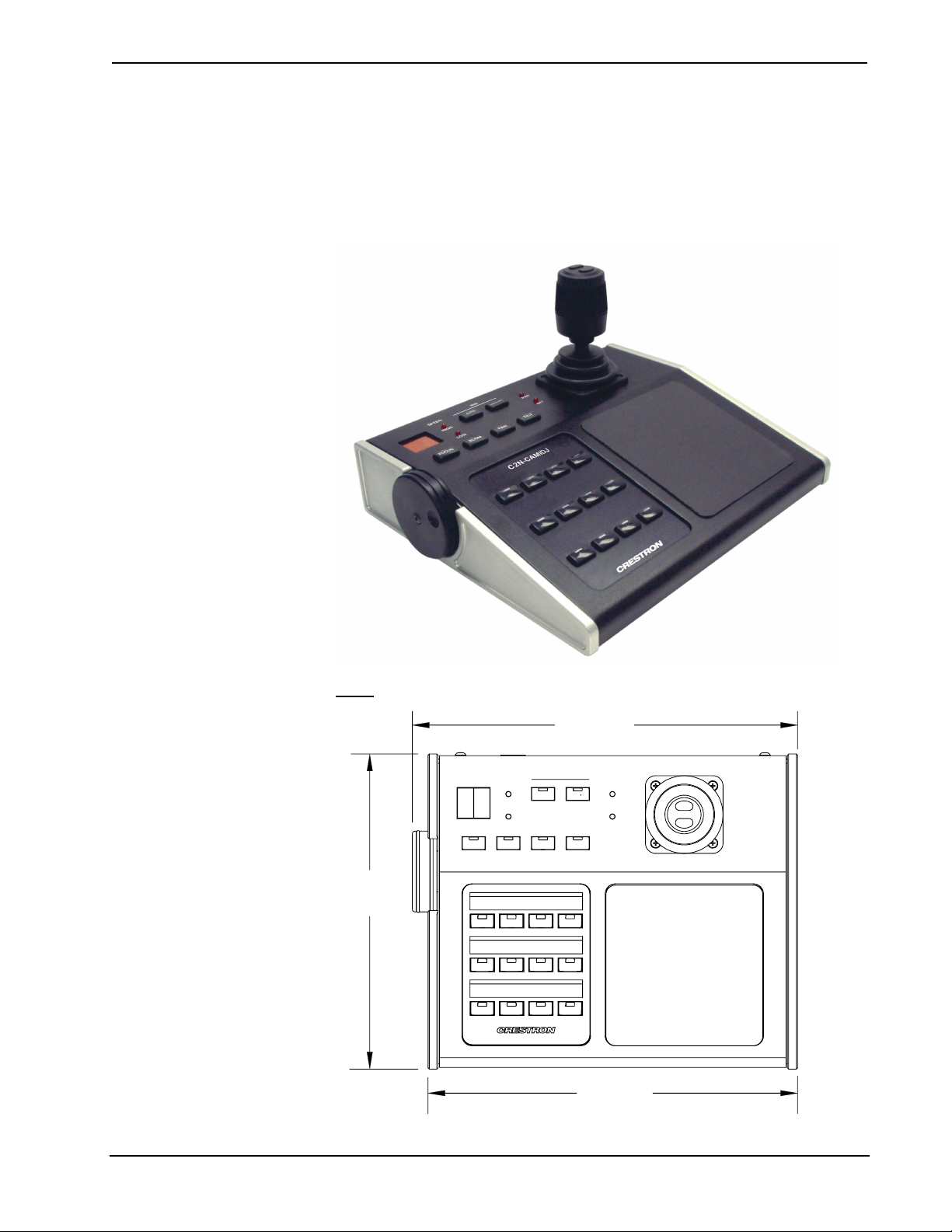
Digital Joystick Camera Controller Crestron C2N-CAMIDJ
2 •Digital Joystick Camera Controller: C2N-CAMIDJ Operations Guide - DOC. 6341
The CAMIDJ can be used alone or in combination with any Crestron touchpanel to
provide the perfect head end for camera control networks of virtually any size. The
supplied example program includes a CamiDJ Interface Module that permits control
of up to four camera pan/tilt heads. Configurations that are more extensive can be
developed using the supplied program as a model. Ideally designed to support
Crestron’s pan/tilt heads and lens interfaces, the CAMIDJ is equally well equipped to
work with third-party pan/tilt heads and integrated PTZ (pan/tilt/zoom) cameras as
part of a complete Crestron control system.
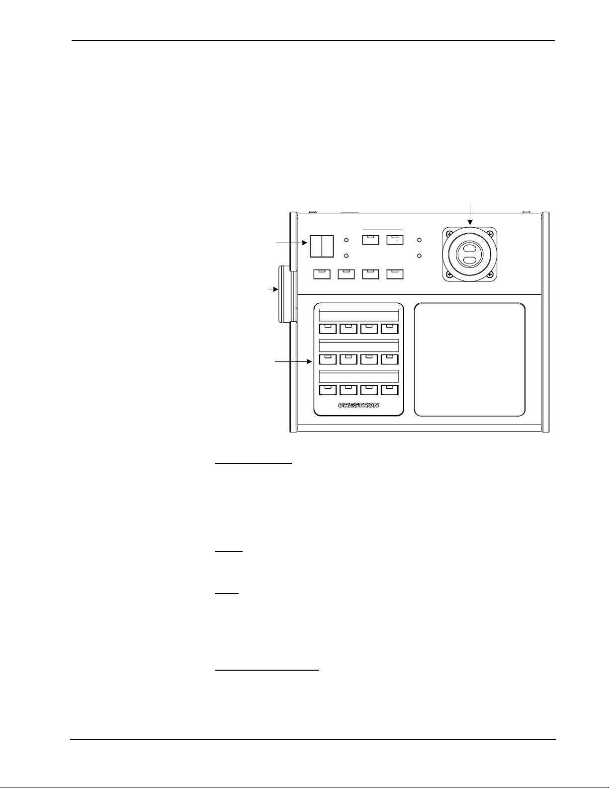
The thumb switches on the top of the joystick select either high or low speed mode.
The speed mode selected is indicated by HIGH and LOW speed mode LED
indicators. The encoder wheel is a rotating knob that allows the operator to operate
the lens focus and iris controls, and to adjust the fast and slow speed scaling values.
The function controlled by the encoder wheel is selected by pushbutton switches on
the top of the unit. For function switches PAN, TILT, and ZOOM, rotation of the
encoder wheel adjusts the high and low speed scaling for each of the functions, as
selected by the joystick thumb switches. The scaling factor is displayed as a number
from 00 to 99 on the two-digit display.
If no further adjustments are made to the wheel within approximately twenty
seconds, the wheel function returns to FOCUS (default). The setting for each speed
mode is stored independently in the control system when using the CamiDJ Interface
Module, not in the CAMIDJ. The user can switch between fast and slow modes of
control using the joystick pushbuttons.
For the FOCUS and IRIS function select buttons, the encoder wheel adjusts the lens
focus or aperture. In the CamiDJ Interface Module, when FOCUS is selected, the
two-digit display indicates “FC.” When Iris MANUAL is selected, the display
indicates “AP” (aperture). The AUTO function select switch puts the iris into auto
mode, allowing the camera to make all iris adjustments. An additional twelve general
purpose select buttons on the top panel are programmable through the Cresnet
network and can be used to control functions such as selecting the camera to be
controlled or setting and recalling presets. The buttons themselves are not
engraveable, but the Crestron Engraver program can be used to create custom labels
for the CAMIDJ to identify the switch functions.