Crestron GLA-LDL-PC-0-10-WL User manual

GLA-LDL-PC-0-10-WL
Dual-Loop Photosensor
Product Manual
Crestron Electronics, Inc.

Original Instructions
The U.S. English version of this document is the original instructions.
All other languages are a translation of the original instructions.
Regulatory Model:
Crestron product development software is licensed to Crestron dealers and Crestron Service Providers (CSPs) under a
limited nonexclusive, nontransferable Software Development Tools License Agreement. Crestron product operating
system software is licensed to Crestron dealers, CSPs, and end-users under a separate End-User License Agreement.
Both of these Agreements can be found on the Crestron website at www.crestron.com/legal/software_license_
agreement.
The product warranty can be found at www.crestron.com/warranty.
The specific patents that cover Crestron products are listed at www.crestron.com/legal/patents.
Certain Crestron products contain open source software. For specific information, visit www.crestron.com/opensource.
Crestron, the Crestron logo, Cresnet, and Zūm are either trademarks or registered trademarks of Crestron Electronics,
Inc. in the United States and/or other countries. UL is either a trademark or registered trademark of Underwriters
Laboratories, Inc. in the United States and/or other countries. Other trademarks, registered trademarks, and trade
names may be used in this document to refer to either the entities claiming the marks and names or their products.
Crestron disclaims any proprietary interest in the marks and names of others. Crestron is not responsible for errors in
typography or photography.
©2022 Crestron Electronics, Inc.

Contents
Overview 5
Physical Description 6
Coverage 7
Light Level Settings 7
Specifications 8
Dimension Drawing 10
Installation 11
Determine the Mounting Location 11
Window Application 11
Skylight Application 12
Desk Level Application 12
Mount the Sensor 13
Flush Mount with Nipple 14
Surface Mount with Screws and Concealed Wires 15
Surface Mount with Screws and Surfaced Wires 16
Wire the Sensor 17
Resources 18
Crestron Support and Training 18
Product Certificates 18
Product Manual — Doc. 9267A Contents • iii

iv • Contents Product Manual — Doc. 9267A

Product Manual — Doc. 9267A GLA-LDL-PC-0-10-WL • 5
Overview
The GLA-LDL-PC-0-10-WL is a dual-loop photosensor that continually measures ambient light
in order to achieve the optimal balance of natural and artificial lighting in daylight harvesting
applications. By harnessing natural daylight from windows and skylights, electrical lighting can
be dimmed, reducing energy usage while maintaining a consistent light level for a more efficient
and comfortable work or living space. With an IP54 rating, the GLA-LDL-PC-0-10-WL is suitable
for indoor, outdoor and wet location applications.
In closed-loop type daylight harvesting applications, the GLA-LDL-PC-0-10-WL is installed on
the ceiling directly above the primary work area. It measures all light within a 60° cone, which
consists predominately of reflected light, acquiring the most natural approximation of perceived
changes in ambient light levels.
In open-loop type daylight harvesting applications, the GLA-LDL-PC-0-10-WL is installed on the
ceiling near a window or in the light well of a skylight, directed toward the incoming daylight and
away from any electrical lighting fixtures. The system estimates the total amount of ambient
lighting in the room according to the light level measured by the photocell.
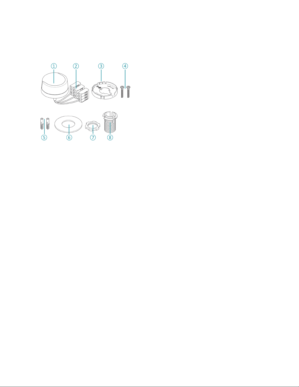
The GLA-LDL-PC-0-10-WL includes hardware to facilitate flush or surface mounting to a
drywall or drop-tile surface. Its simple 3-wire interface allows for direct connection to a
Crestron® control system via a single Versiport I/O or analog input port, with 24 V power taken
from the Cresnet® network control bus.
NOTE: Cresnet communications requires a GLS-SIM or ZUMMESH-JBOX-SIM (both are sold
separately). Power may be taken from Cresnet bus regardless of interface method.
Connects to a GLS-SIM, ZUMMESH-JBOX-SIM, Versiport I/O, or Analog Input control port
on any Crestron control system.
Using an optional sensor integration module (GLS-SIM or ZUMMESH-JBOX-SIM for a Zūm® J-
Box, both sold separately), the GLA-LDL-PC-0-10-WL becomes a full-featured Cresnet device,
streamlining the total lighting system. Cresnet provides a simple solution for configuring and
wiring sensors as part of any complete Crestron system. The Cresnet bus is the communications
backbone for many Crestron keypads, lighting controllers, shade motors, sensors, and other
devices.

6 • GLA-LDL-PC-0-10-WL Product Manual — Doc. 9267A
Physical Description
This section provides a breakdown of the physical components of the device.
① Photo Cell 0-10V
② Wires including WAGOconnectors
③ Back plate
④ Screws
⑤ Dowels
⑥ Washer
⑦ Lock nut
⑧ 1/2 in. threaded chase nipple

Product Manual — Doc. 9267A GLA-LDL-PC-0-10-WL • 7
Coverage
Depending on the application, the sensor has two possible fields of view. This is set by installing
jumpers as described in the Light Level Settings section below.
① Sensor field of view when using Open Loop Control (OL)
② Sensor field of view when using Closed Loop Control (CL)
Light Level Settings
Jumpers are used to set the light level range and sensor field of view.
The following options can be set by installing jumpers in the specified locations:
A. OL: 3-300 fc (factory default)
B. OL: 30-3000 fc
C. OL: 60-6000 fc
D. CL: 3-300 fc

Product Manual — Doc. 9267A GLA-LDL-PC-0-10-WL • 8
Specifications
Sensing
Field of view 60° cone
Light sensitivity CL: 3-300 fc
OL: 3-6000 fc
Center axis CL: 90°
OL: 45°
Controls and Connections
Light sensitivity settings OL: 3-300 fc (factory setting);
OL: 30-3000 fc;
OL: 60-6000 fc;
CL: 3-300 fc
NOTE: Field of view and light sensitivity are set by installing jumpers on the
device.
Flying leads (1) Red Input flying lead; 24VDC power input;
(1) Black Ground flying lead;
(1) Orange Output flying lead;
Recommend wire size:18AWG;
Light level control signal output;
Provides 0-10V analog control signal proportionate to the ambient light level;
Connects to a Crestron® sensor integration module (GLS-SIM or
ZUMMESH-JBOX-SIM, sold separately) or to a Versiport I/O or Analog Input
control port on any Crestron control system
Power Requirements
Current Consumption 2mA class 2 at 24VDC
Cresnet Power Usage ~.1 W;
Cresnet communications requires a GLS-SIM or ZUMMESH-JBOX-SIM (both
are sold separately). Power may be taken from Cresnet bus regardless of
interface method. Connects to a GLS-SIM, ZUMMESH-JBOX-SIM, Versiport
I/O, or Analog Input control port on any Crestron control system.
Environmental
Temperature -40° to 158°F (-40° to 70°C)
For indoor or outdoor use
IPRating IP54

9 • GLA-LDL-PC-0-10-WL Product Manual — Doc. 9267A
Housing
Construction High-impact injection-molded plastic
Mounting Surface or flush ceiling mount directly to drywall or drop-tile
Dimensions
Height 1.06 in. (27 mm)
Diameter 2.01 in. (51 mm)
Weight
.011 lb (.05 kg)
Compliance
UL® Listed

Product Manual — Doc. 9267A GLA-LDL-PC-0-10-WL • 10
Dimension Drawing

Product Manual — Doc. 9267A GLA-LDL-PC-0-10-WL • 11
Installation
This section contains all the information needed to install the GLA-LDL-PC-0-10-WL.
Determine the Mounting Location
The GLA-LDL-PC-0-10-WL can be used in several different applications, with specific
considerations for each.
Window Application
Where windows are the primary source of daylight, mount the photo cell on the ceiling between
the window and the first row of fixtures.
1. Install jumpers to set the light level to option B (Open Loop Control, 30-3000 fc).
2. Place the photo cell 12 to 19 inches from the window.
3. Point the photo cell towards the window.
NOTE:Do not expose the photo cell to direct illumination from electric light sources.

12 • GLA-LDL-PC-0-10-WL Product Manual — Doc. 9267A
Skylight Application
Mount the photo cell in the lightwell of the skylight.
1. Orient the photo cell towards the incoming daylight.
2. Install jumpers to set the light level to option C (Open Loop Control, 60-6000 fc).
Desk Level Application
Mount the photo cell above the working space so that it reads the light level generated by both
the electric light sources and the natural light coming through nearby windows.
lThe ambient light level will fluctuate in different areas of the room due to several factors,
such as fixtures, window locations, and wall colors. The device should be placed in a
location with average light levels.
lInstall jumpers to set the light level to option D (Closed Loop Control, 3-300 fc).
NOTE:Because furniture can impact the light levels, this should only be completed when the
room is fully furnished.

Product Manual — Doc. 9267A GLA-LDL-PC-0-10-WL • 13
Mount the Sensor
Follow these guidelines to correctly mount the GLA-LDL-PC-0-10-WL.
lThe photo cell lens must face towards a window.
lMount the GLA-LDL-PC-0-10-WL on a vibration-free surface.
lThe back plate and sensor head must be lined up correctly:
CAUTION: The gasket is required to maintain the IP54 rating. During installation, do not pull
out the complete gasket. Instead, carefully lift up the edge covering the jumpers.
Regardless of installation location, there are three ways to mount the GLA-LDL-PC-0-10-WL.

14 • GLA-LDL-PC-0-10-WL Product Manual — Doc. 9267A
Flush Mount with Nipple
With this option, wires run through the nipple and can be concealed within the ceiling. Follow the
steps below.
1. Hold the back plate in the mounting location and mark the center of the wire run hole.
2. With a 23/32 in. drill bit, carefully drill the hole for the wire run.
3. Snap the threaded chase nipple onto the back of the back plate.
4. Install jumpers to set the light level range and field of view.
5. Remove the WAGOconnectors and pull the wires from the sensor through the back plate
and threaded chase nipple.
6. Insert the wires into the drilled hole.
7. Place the washer over the wires and threaded chase nipple.
8. Using the lock nut, secure the threaded chase nipple in place.
9. Using the WAGOconnectors, connect the three individual sensor wires (black, red, and
orange) to the incoming wires.
10. Rotate the photo cell lens to face in the desired direction.

Product Manual — Doc. 9267A GLA-LDL-PC-0-10-WL • 15
Surface Mount with Screws and Concealed Wires
Use this option when the nipple cannot be used, such as through concrete. Follow the
instructions below.
1. Hold the back plate in the mounting location, taking care to align it so that the photo cell
lens is pointed in the desired direction.
NOTE: To align the sensor correctly, line up the key on the sensor to the key slot on the
back plate.
2. Mark the locations for the two mounting holes and the center hole.
3. Using a 1/8 in. drill bit, carefully drill pilot holes in the two marked locations.
4. Using a 23/32 in. drill bit, carefully drill the hole for the wire run.
5. Insert a plastic dowel in each of the 1/8 in. drilled holes.
6. Align the back plate and secure it with the screws, taking care to align it so that the sensor
lens points in the desired direction.
7. Pull the wire run through the drilled 23/32 in. hole.
8. Install jumpers to set the light level range and field of view.
9. Using the WAGOconnectors, connect the three individual sensor wires (black, red, and
orange) to the incoming wires.
10. Push the wires one at a time through the center hole in the back plate.
11. Align the sensor key and snap the sensor into the back plate.

16 • GLA-LDL-PC-0-10-WL Product Manual — Doc. 9267A
Surface Mount with Screws and Surfaced Wires
Use this option when the nipple cannot be used and the wires are being run through the side of
the GLA-LDL-PC-0-10-WL's housing. Follow the instructions below.
1. Hold the back plate in the mounting location, taking care to align it so that the photo cell
lens is pointed in the desired direction.
NOTE: To align the sensor correctly, line up the key on the sensor to the key slot on the
back plate.
2. Mark the locations for the two mounting holes and the center hole.
3. Using a 1/8 in. drill bit, carefully drill pilot holes in the two marked locations.
4. Using a 23/32 in. drill bit, carefully drill the hole for the wire run.
5. Insert a plastic dowel in each of the 1/8 in. drilled holes.
6. Align the back plate and secure it with the screws, taking care to align it so that the photo
cell lens points in the desired direction.
7. Locate the wire entry knockout of the back plate. This is where the wires will pass through.
8. Install jumpers to set the light level range and field of view.

Product Manual — Doc. 9267A GLA-LDL-PC-0-10-WL • 17
9. Connect the incoming wires to each of the three sensor wires (black, red, and orange). Use
a wire connector small enough to fit between the sensor and the back plate when
assembled.
NOTE: Wire connectors for this mounting option are not included.
10. Align the sensor key and snap the sensor into the back plate.
11. Secure the wires running to the sensor with cable clips to prevent the wires from sagging.
NOTE:Cable clips are not included.
Wire the Sensor
Light measurement is made with the black and orange wires. Verify the wiring is correct to avoid
damage to the controller, lighting and connected control devices.
WARNING: Ensure that the power has been switched off at the breaker before wiring the
GLA-LDL-PC-0-10-WL. Verify that the circuit is inactive with a voltage meter.

Product Manual — Doc. 9267A GLA-LDL-PC-0-10-WL • 18
Resources
The following resources are provided for the GLA-LDL-PC-0-10-WL.
NOTE:You may need to provide your Crestron.com web account credentials when prompted
to access some of the following resources.
Crestron Support and Training
lCrestron True Blue Support
lCrestron Resource Library
lCrestron Online Help (OLH)
lCrestron Training Institute (CTI)Portal
Product Certificates
To search for product certificates, refer to support.crestron.com/app/certificates.

This page is intentionally left blank.
Product Manual — Doc. 9267A GLA-LDL-PC-0-10-WL • 19

Crestron Electronics, Inc.
15 Volvo Drive, Rockleigh, NJ 07647
Tel: 888.CRESTRON
Fax: 201.767.7656
www.crestron.com
Product Manual — Doc. 9267A
09/16/22
Specifications subject to
change without notice.
Table of contents
Other Crestron Measuring Instrument manuals
Popular Measuring Instrument manuals by other brands

Centech
Centech CEN-TECH 92340 Assembly and operating instructions

Aqualytic
Aqualytic AL10Con instruction manual

Bin Master
Bin Master GWR-3000 operating instructions

Check-line
Check-line DT-735 Operation manual

Blackline Safety
Blackline Safety G7 EXO Technical user's manual

Unit
Unit UTL8500 Series user manual