CrewPlex DR10-900 User manual

Operating manual
DR10-900
CrewPlex, LLC
205 Technology Parkway
Auburn, Alabama 36830 USA
Phone +1.334.321.1400
Fax +1.334.321.1162
www.crewplex.com
COPYRIGHT © 2020-2023 CrewPlex, LLC. All rights reserved. CrewPlex® and SmartBoom® are trademarks of CoachComm, LLC.
All other trademark references in this document are property of their respective owners.
Document Reference: D0000591_E

ii / ii
CONTENTS
INTRODUCTION....................................................................................................................................... 1
WHAT’S INCLUDED WITH DR10-900?.................................................................................................2
CONTROLS ...............................................................................................................................................3
DISPLAY INDICATORS ............................................................................................................................3
SETUP........................................................................................................................................................4
BATTERY...................................................................................................................................................5
TWO-WAY RADIO INTEGRATION .........................................................................................................6
OPERATION..............................................................................................................................................7
MENU SETTINGS......................................................................................................................................8
RECOMMENDED SETTINGS BY HEADSET........................................................................................... 10
DEVICE SPECIFICATIONS ...................................................................................................................... 11
PRODUCT CARE AND MAINTENANCE ................................................................................................12
PRODUCT SUPPORT ............................................................................................................................... 12
LICENSE INFORMATION.........................................................................................................................13
CREWPLEX WARRANTY STATEMENT ................................................................................................. 14

1 / 14
INTRODUCTION
We at CrewPlex™want to thank you for purchasing DR10-900. DR10-900 is a robust, two-channel,
full-duplex, multi-user, wireless intercom system that operates in the 900MHz frequency band to
provide superior range and performance, all without the need for a basestation. The system features
lightweight beltpacks and provides exceptional sound quality, enhanced noise cancellation, and
long-life battery operation. In addition, the DR10-900’s IP67-rated beltpack is built to endure the
wear and tear of everyday use, as well as the extremes of outdoor environments.
In order to get the most out of your new DR10-900, please take a few moments to read this manual
completely so that you better understand the operation of this product. This document applies to
model CP-DR10-900. For questions not addressed in this manual, feel free to contact the CrewPlex
Customer Support Department using the information on page 12.
PRODUCT FEATURES
• Robust, Two-Channel System
• Dual Listen
• Simple to Operate
• Up to 10 Full-Duplex Users
• Pack-to-Pack Communication
• Unlimited Listen-Only Users
• Unlimited Shared Users
• 900MHz Frequency Band
• Encrypted FHSS Technology
• Ultra Compact, Small, and Lightweight
• Rugged, IP67-Rated BeltPack
• Long, 12-Hour Battery Life
• Field-Replaceable Battery
• Available Drop-In Charger
• Available Two-Way Radio Integration
• Multiple Headset and Earset Options

2 / 14
WHAT’S INCLUDED WITH DR10-900?
• BeltPack
• Li-Ion Battery (Installed during shipment)
• USB Charging Cable
• BeltPack Antenna (Attach to beltpack prior to operation.)
• Quick Start Guide
• Product Registration Card
OPTIONAL ACCESSORIES
Part Number Description
CrewPlex Accessories
CAC-USB6-CHG CrewPlex 6-Port USB Charger
CAC-CPDR-5CASE IP67-rated CrewPlex Hard Travel Case
CAC-CP-SFTCASE CrewPlex Soft Travel Case
CPBT-DRC-55 CrewPlex DR10 5+5 Drop-In BeltPack and Battery Charger
CP-REC-900 CrewPlex 900MHz Receiver
Headsets and Adapter Accessories
CHS-SB11LE-DMG SmartBoom® LITE Single Ear CrewPlex Headset with Dual Mini Connector for DR5 and DR10
CHS-SB110E-DMG SmartBoom PRO Single Ear CrewPlex Headset with Dual Mini Connector for DR5 and DR10
CHS-SB210E-DMG SmartBoom PRO Dual Ear CrewPlex Headset with Dual Mini Connector for DR5 and DR10
CHS-HH210R-DMG CrewPlex Hard Hat/Helmet Headset with Dual Mini Connector for DR5 and DR10
CHS-HHLTL-DMG CrewPlex Hard Hat/Helmet In-Ear Headset with Dual Mini Connector for DR5 and DR10
CHS-IEL-M CrewPlex In-Ear Headset, Single Ear Left Only with Single Mini Connector for DR5 and DR10
CHS-IELPTT-M CrewPlex In-Ear Headset with Push-To-Talk (PTT) Button, Single Ear Left Only with Single Mini
Connector for DR5 and DR10
CHS-LAV-DM CrewPlex Lavalier Microphone and Eartube with Dual Mini Connector for DR5 and DR10
CHS-LAVPTT-DM CrewPlex Lavalier Microphone and Eartube with Push-To-Talk (PTT) Button with Dual Mini
Connector for DR5 and DR10
CAC-2-1-ADPT CrewPlex 2 3.5 mm to 1 3.5 mm Headset Adapter for DR5, DR10, or CRC-2WAY-IO
CAC-TRI-6FT
CrewPlex 6-Foot Compact Tripod Kit
Two-Way Radios and Adapter Accessories
CRC-2WAY-IO CrewPlex Two-Way Radio In/Out Adapter for DR10 series (requires additional two-way radio
cable)
CRC-MOT-X83 CrewPlex Two-Way Radio Adapter Cable for Motorola Radios
CRC-MOT-11M12PA CrewPlex Two-Way Radio Adapter Cable (Motorola) 11M 12 Pin-A
CRC-MOT-11M8P CrewPlex Two-Way Radio Adapter Cable (Motorola) 11M 8 Pin
CRC-KEN-2P CrewPlex Two-Way Radio Adapter Cable for Kenwood Radios
CRC-INT-IO Interface Cable for Wired Intercom Audio In/Out
3 / 14
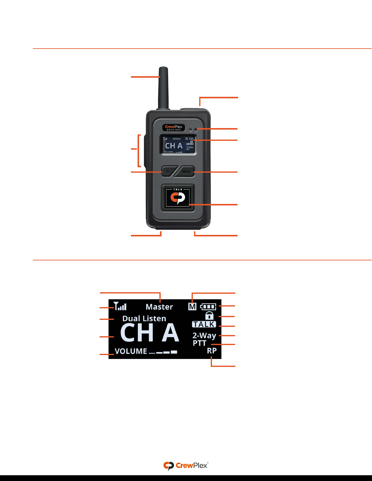
CONTROLS
DISPLAY INDICATORS
Status/Charge LED
Power Button
Talk Button
Headset Connection
USB Charger
Connection
Volume +/– Buttons
Mode Button
Short press to change channel
Long press to enter menu
OLED Screen
Antenna
Top Button
Master Pack Indicator
Battery Status
Mode Indicator
Signal Indicator
Talk Indicator
2-Way Enabled Indicator
Push-To-Talk Indicator
Lock Indicator
User Role
Active Channel
Volume Level
Dual Listen
Indicator

4 / 14
SETUP
1. Attach the beltpack antenna. It is reverse threaded; screw counter-clockwise.
2. Connect a headset to the beltpack. Press firmly until it clicks to make sure the headset connector
is seated properly.
3. Power on. Press and hold the POWER button for two (2) seconds until the screen turns on.
4. Access the menu. Press and hold the MODE button for three (3) seconds until the screen changes
to <SETTING MODE>. Short-press MODE to scroll through the settings, and then scroll through
setting options using VOLUME +/−. Press and hold MODE to save your selections and exit the
menu.
a. Select a Group. Select a group number from 00–51.
Important: BeltPacks must have the same group number to communicate.
IF OPERATING THE BELTPACK IN REPEATER MODE*
b. Select an ID. Select a unique ID number.
• Repeater Mode ID options: M (Master), 01–08 (Full Duplex), S (Shared), L (Listen).
• One beltpack
must
always
use the “M” ID and serve as the Master for proper system
function. An “M” indicator designates the Master beltpack on its OLED.
• Listen-only beltpacks must use the “L” ID. You may duplicate ID “L” on multiple beltpacks.
• Shared beltpacks must use the “S” ID. You may duplicate ID “S” on multiple beltpacks, but
only one shared beltpack may talk at a time.
• When using “S” IDs, the last full-duplex ID (“08”) cannot be used in the Repeater Mode.
c. Confirm BeltPack’s Security Code. BeltPacks must use the same security code to work
together as a system.
*Repeater Mode is the default setting. See page 9 for information about changing mode.
IF OPERATING THE BELTPACK IN ROAM MODE**
b. Select an ID. Select a unique ID number.
• Roam Mode ID options: M (Master), SM (Submaster), 02-09, S (Shared), L (Listen).
• One beltpack must always be “M” ID and serve as the Master, and one beltpack must always
be set to “SM” and serve as the Submaster for proper system function.
• The Master and Submaster must be located in positions where they always have an
unobstructed line of sight to each other.
• Listen-only beltpacks must use the “L” ID. You may duplicate ID “L” on multiple beltpacks.
• Shared beltpacks must use the “S” ID. You may duplicate ID “S” on multiple beltpacks, but
only one shared beltpack may talk at a time.
• When using “S” IDs, the last full-duplex ID (“09”) cannot be used in the Roam Mode.

5 / 14
c. Access the Roaming Menu. Select a Roaming menu selection for each beltpack.
• Auto – Allows the beltpack to automatically log in to the Master or Submaster depending
on the environment and the beltpack’s proximity to either.
• Manual – Allows the user to manually select whether the beltpack is logged in to the Master
or Submaster. Press the MODE button to select Master or Submaster.
• Master – When selected, the beltpack is locked into only logging into the Master.
• Submaster – When selected, the beltpack is locked into only logging into the Submaster.
d. Confirm BeltPack’s Security Code. BeltPacks must use the same security code to work
together as a system.
**When in Roam Mode, the two-way radio Top Button menu options and the Dual Listen function will not be available. See page 9
for information about changing mode.
IF OPERATING THE BELTPACK IN STANDARD MODE
b. Select an ID. Select a unique ID number.
• Standard Mode ID options: M (Master), 01–09 (Full Duplex), S (Shared), L (Listen).
• One beltpack
must
always
use the “M” ID and serve as the Master for proper system
function. An “M” indicator designates the Master beltpack on its OLED.
• Listen-only beltpacks must use the “L” ID. You may duplicate ID “L” on multiple beltpacks.
• Shared beltpacks must use the “S” ID. You may duplicate ID “S” on multiple beltpacks, but
only one shared beltpack may talk at a time.
• When using “S” IDs, the last full-duplex ID (“09”) cannot be used in the Standard Mode.
c. Confirm BeltPack’s Security Code. BeltPacks must use the same security code to work
together as a system.
BATTERY
The rechargeable Lithium-ion battery is installed in the device at shipment. To recharge the battery,
either 1) plug the USB charging cable into the device USB port or 2) connect the device to the
drop-in charger (CPBT-DRC-55, sold separately). The LED in the top right corner of the device
will illuminate solid red while the battery is charging and will turn o once the battery is fully
charged. The battery charge time is approximately 3.5 hours from empty (USB port connection) or
approximately 6.5 hours from empty (drop-in charger). The beltpack may be used while charging,
but doing so may lengthen battery charge time.
6 / 14
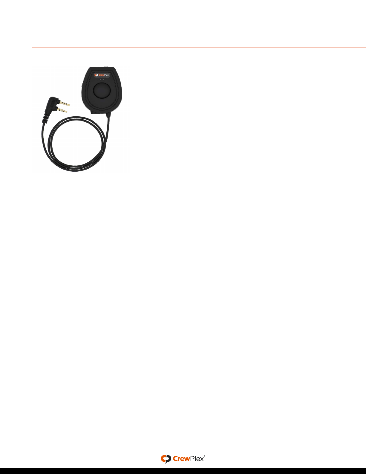
TWO-WAY RADIO INTEGRATION
TWO-WAY I/O HEADSET ADAPTER ACCESSORY
The DR10 system can be integrated with a two-way radio
system via the CrewPlex Two-Way I/O Headset Adapter
(CRC-2WAY-IO). The DR10 system oers two basic modes of
operation when interfacing and connecting to two-way radio
systems. The Local mode allows users to connect to a two-way
radio and keep their conversations private from the other DR10
system users. Only the DR10 user in Local mode can hear and
talk to the users on the two-way system. The System mode
allows a two-way radio to be connected to a DR10 system and
all users can hear and talk using the connected two-way radio.
See the CRC-2WAY-IO Quick Start Guide for more information
on the CrewPlex Two-Way I/O Headset Adapter.
CONNECTING A TWO-WAY RADIO TO THE SYSTEM
1. Ensure that two-way radios and CrewPlex BeltPacks are powered o.
2. Connect the CrewPlex Two-Way I/O Headset Adapter (CRC-2WAY-IO) to the Master beltpack’s
dual-mini headset port. (The adapter connector prong marked with “R” should be inserted into
the beltpack’s “RPT” port.)
3. Use the appropriate two-way radio cable to connect the adapter to the two-way radio.
4. If desired, connect a CrewPlex Two-Way I/O Headset Adapter to each additional beltpack
needing remote push-to-talk ability. (Users with a secondary adapter may push to talk from the
adapter instead of the beltpack.)
5. On the CrewPlex Two-Way I/O Headset Adapter top switch, choose System or Local.
6. Power on the two-way radios and beltpacks.
7. Set the volume of the two-way radio connected to the beltpack to 50%. (You may adjust its
volume further if desired once setup is complete.)
8. In the beltpack menu, choose a function for the Top Button (see "Menu Settings" on page 8
below for more information).
9. Enable TALK on the Master beltpack. This ensures that audio from the two-way radio will be
heard in the CrewPlex system when the Master beltpack does not have its Top Button engaged.
10. Press and hold a beltpack’s Top Button to talk to all beltpacks (on the active channel) and to all
connected two-way radios (System Mode). In Local Mode, the Top Button will only send audio to
other two-way radios.
Figure 1: CrewPlex Two-Way I/O
Headset Adapter (CRC-2WAY-IO)

7 / 14
OPERATION
• LED Modes - LED is blue and double blinks when logged in and
single blinks when logged out. LED is red when battery charging is in
progress. LED turns o when charging is complete.
• Lock - To toggle between Lock and Unlock, press and hold the TALK
and MODE buttons simultaneously for three (3) seconds. A lock icon
appears on the OLED when locked. This function locks the TALK
and MODE buttons, but it does not lock headset volume control, the
POWER button, or the PTT button.
• Volume Up and Down - Use the +and −buttons to control the
headset volume. “Volume” and a stair-step indicator display the
beltpack’s current volume setting on the OLED. You will hear a beep in
your connected headset when the volume is changed. You will hear a
dierent, higher-pitched beep when maximum volume is reached.
• Talk - Use the TALK button to enable or disable talk for the device.
“TALK” appears on the OLED when enabled.
» Latch talking is enabled/disabled with a single, short press of the
button.
» Momentary talking is enabled by pressing and holding the button
for two (2) seconds or longer; talk will remain on until the button is
released.
» Shared users (“S” ID) can enable talk for their device with the
momentary talking function (press and hold while talking). Only
one Shared user can talk at a time.
• Mode - Short-press the MODE button to toggle between the channels
enabled on the beltpack. Long-press the MODE button to access the
menu.
• Dual Listen - When Dual Listen is on, users will be able to hear both
Channel A and B while talking only on the currently selected channel.
• Two-Way Push-to-Talk - If you have a two-way radio connected to the
Master beltpack, you may use the Top Button to activate talk for the
two-way radio.
• Out of Range Tones - The user will hear three quick tones when the
beltpack logs out of the system, and they will hear two quick tones
when it logs in.
OPERATING MULTIPLE DR10-900 SYSTEMS IN ONE
LOCATION
Each separate DR10-900 system should use the same Group and
Security Code for all beltpacks in that system. CrewPlex recommends that
systems operating in proximity to one another set their Groups to be at
least ten (10) values apart. For example, if one system is using Group 03,
another system nearby should use Group 13.
Figure 2: Lock Indicator
Figure 3: Volume Setting
Figure 4: Talk Indicator
Figure 5: Channel Indicator
Figure 6: Dual Listen Indicator
Figure 7: Two-Way PTT
Indicator

8 / 14
MENU SETTINGS
The following table lists adjustable settings and options. To adjust these settings from the beltpack
menu, follow the instructions below.
1. To access the menu, press and hold the MODE button for three (3) seconds until the screen
changes to <Setting Mode>.
2. Short-press the MODE button to scroll through the settings: Group, ID, Side Tone, Mic Gain,
Channel A, Channel B, Security Code, Roaming (only in Roam Mode), Dual Listen, and Top Button.
3. While viewing each setting, you may scroll through its options using the VOLUME +/−buttons;
then, continue to the next menu item by pressing the MODE button. See the table below for the
available options under each setting.
4. Once you finish your changes, press and hold MODE to save your selections and exit the menu.
Setting Default Options Description
Group N/A 00–51 Coordinates operation for beltpacks communicating as
a system. BeltPacks must have the same group number
to communicate.
ID N/A M
SM
01-08
02-09
01–09
S
L
Master ID
Submaster ID (Only available in Roam mode - see Tech
Menu below.)
Repeater* Mode ID options
Roam Mode ID options
Standard Mode ID options
Shared
Listen-Only
Side Tone O On, O Allows you to hear yourself while talking. Louder
environments may require you to enable your side tone.
Mic Gain 1 1–8 Determines the headset microphone audio level being
sent from the microphone pre amp.
Channel A On On, O
Channel B On On, O (Not available in Roam Mode.)
Security Code
(“SEC Code”)
0000 4-digit alpha-
numeric code
Limits access to a system. BeltPacks must use the same
security code to work together as a system.
Roaming Auto Auto, Manual,
Submaster,
Master
Determines whether a beltpack can switch between
the Master and Submaster beltpacks. (Only available in
Roam mode - see Tech Menu below.)
Dual Listen O On, O Allows the user to listen to both Channel A and B while
talking on the currently selected channel. (Not available
in Roam mode - see Tech Menu below.)

9 / 14
Setting Default Options Description
Top Button O Channel Switch,
Channel Switch
+ Trigger, Trigger
Local, Trigger
System, O
Determines the beltpack’s top button behavior when a
two-way radio is connected to the system. (Not avail-
able in Roam mode - see Tech Menu below.)
*Repeater Mode is the default setting. See page 9 for information about changing mode.
TOP BUTTON - MENU SETTING INFORMATION
The BeltPack Top Button can be set to dierent modes for use with two-way integration.
• Channel Switch: When the beltpack is set to “Channel Switch,” a press and hold of the top button
on the beltpack will allow the user to momentarily switch channels to talk and listen on the
beltpacks other channel. When the top button is released, the beltpack returns to the channel it
was previously on.
• Channel Switch and Trigger: When the beltpack is set to “Channel Switch and Trigger,” a press and
hold of the top button on the beltpack will allow the user to momentarily switch channels to talk
and listen on the beltpacks other channel while also triggering an attached System-mode two-way
radio. When the top button is released, the beltpack returns to the channel it was previously on.
• Trigger Local: When the pack is set to “Trigger Local,” the top button on the beltpack will trigger
an attached Local-mode two-way radio’s PTT.
• Trigger System: When the pack is set to “Trigger System,” the top button on the beltpack will
trigger an attached System-mode two-way radio’s PTT.
• O: When the pack is set to “O,” the top button will do nothing when pressed.
TECH MENU - MODE SETTING CHANGE
The mode can be changed between three settings for dierent functionality:
• Repeater Mode* connects users working beyond line of sight from one another by locating the
Master beltpack in a prominent central location.
• Roam Mode connects users working beyond line of sight as well as extends the range of the DR10
system by strategically locating the Master and Submaster beltpacks.
• Standard Mode connects users where line of sight between users is possible.
*Repeater Mode is the default setting.
Follow the instructions below to change the mode.
1. Access the beltpack’s Tech Menu by simultaneously pressing and holding the TOP BUTTON and
MODE until <Tech Menu> displays.
2. Scroll between the “RP,” “RM,” and “ST” options using the VOLUME +/−buttons.
3. Press and hold MODE to save your selections and exit the Tech Menu. The beltpack will
automatically power o.
4. Press and hold the POWER button for two (2) seconds; the beltpack will power back on and will
be using the newly selected mode.
10 / 14
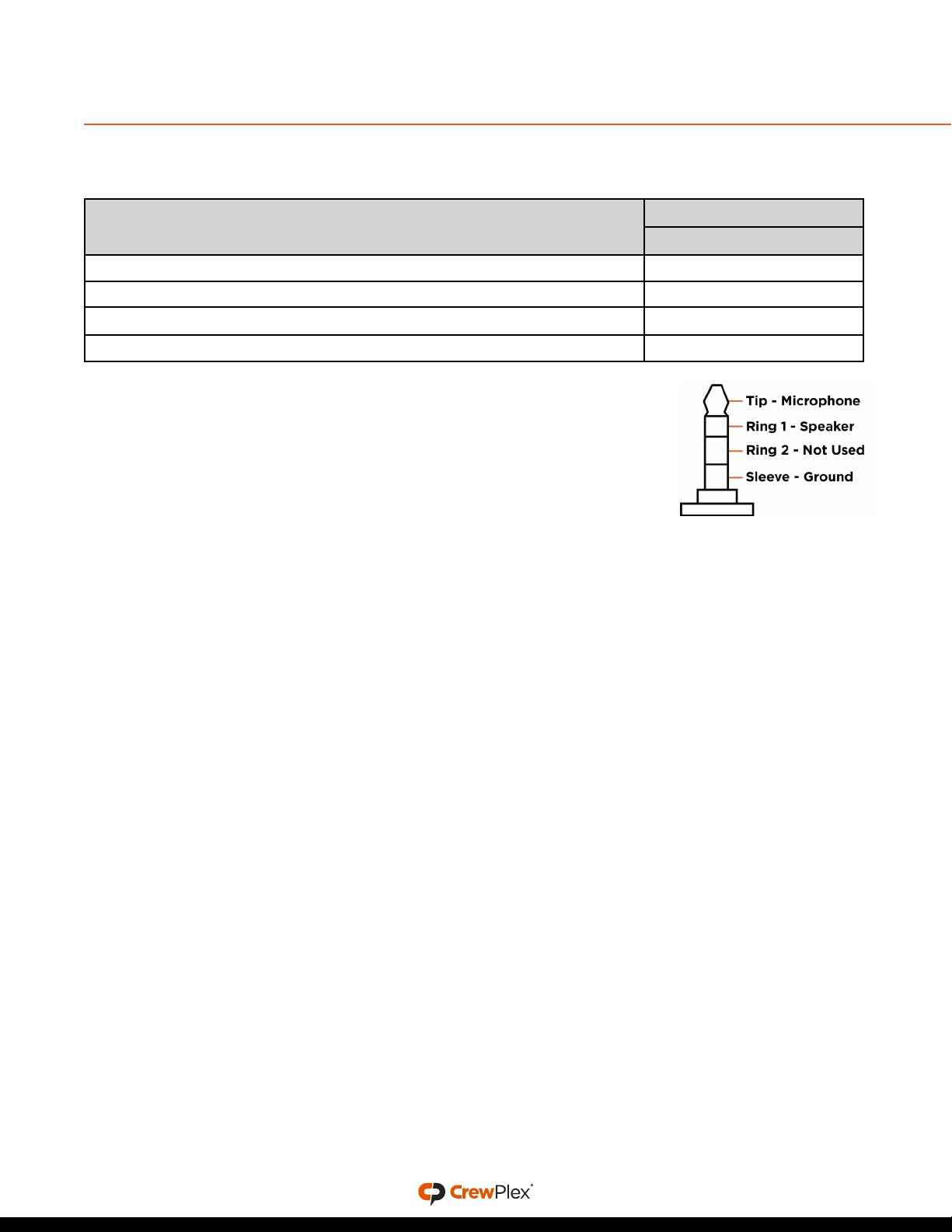
RECOMMENDED SETTINGS BY HEADSET
The following table provides recommended DR10-900 settings for several common headset models.
Use the diagram of the wiring for the beltpack’s TRRS connector if you
choose to connect your own headphones. The microphone bias voltage
range is 1.9V DC unloaded and 1.3V DC loaded.
Headset Model Recommended Setting
Mic Gain
SB & SBL (CHS-SB11LE-DMG, CHS-SB110E-DMG, CHS-SB210E-DMG) 1
CHS-HH210R-DMG 6
CHS-HHLTL-DMG 4
CHS-IEL-M
7
Figure 8: TRRS Connector

11 / 14
DEVICE SPECIFICATIONS
Specification* CP-DR10-900
Radio Frequency Type ISM 902–928 MHz
Radio Interface GFSK with FHSS
Voice Codec 16 bit / 8kHz
Maximum Eective Isotropically Radiated Power (EIRP) 400 mW
Rx Sensitivity -95 dBm
Frequency Channels 52
Frequency Response 50 Hz ~ 4 kHz
Encryption AES 128
Channel Spacing 0.5 MHz
Number of Talk Channels 2
Maximum Full-Duplex Users 10
Number of Shared Users Unlimited
Number of Listen Only Users Unlimited
Antenna Detachable 1 dBi Helical Antenna
Battery Type Rechargeable 3.7V; 2,000 mA Li-ion
field-replaceable battery
Battery Life Approx. 12 hours
Battery Charging Time 3.5 hours (USB cable)
6.5 hours (Drop-in charger)
Charge Type USB Micro; 5V; 1–2 A
Dimension (with Belt Clip) 4.83 in. (H) × 2.64 in. (W) × 1.22 in. (D)
[122.7 mm (H) × 67 mm (W) × 31 mm (D)]
Weight 6.35 oz. (180 g)
Display OLED
*
Notice about Specifications: While CrewPlex makes every attempt to maintain the accuracy of the information contained in its
product manuals, that information is subject to change without notice. Performance specifications included in this manual are design-
centered specifications and are included for customer guidance and to facilitate system installation. Actual operating performance
may vary. Manufacturer reserves the right to change specifications to reflect latest changes in technology and improvements at any
time without notice.

12 / 14
PRODUCT CARE AND MAINTENANCE
Clean using a soft, damp cloth.
CAUTION: Do not use cleaners that contain solvents. Keep liquid and foreign objects out of the device openings. If the product is
exposed to rain, gently wipe o all surfaces, cables, and cable connections as soon as possible and allow unit to dry before storing.
PRODUCT SUPPORT
CrewPlex oers technical support via phone and email from 07:00 to 19:00 Central Time
(UTC−06:00), Monday through Friday.
+1.334.321.1400
customer.support@crewplex.com
Visit www.crewplex.com for product support references and helpful documentation.
RETURNING EQUIPMENT FOR REPAIR OR MAINTENANCE
All questions and/or requests for a Return Authorization Number should be directed to the Customer
Service Department (customer.service@crewplex.com). Do not return any equipment directly to the
factory without first obtaining a Return Material Authorization (RMA) Number. Obtaining a Return
Material Authorization Number will ensure that your equipment is handled promptly.
All shipments of CrewPlex products should be made via UPS, or the best available shipper, prepaid
and insured. The equipment should be shipped in the original packing carton; if that is not available,
use any suitable container that is rigid and of adequate size to surround the equipment with at least
four inches of shock-absorbing material. All shipments should be sent to the following address and
must include a Return Material Authorization Number:
CrewPlex Customer Service Department
Attn: Return Material Authorization #
205 Technology Parkway
Auburn, AL USA 36830-0500

13 / 14
LICENSE INFORMATION
CREWPLEX DR10-900 FCC COMPLIANCE STATEMENT
00004394 (FCCID: YJH-GM-900MSS)
This equipment has been tested and found to comply with the limits for a Class B digital device,
pursuant to Part 15 of the FCC Rules. These limits are designed to provide reasonable protection
against harmful interference in a residential installation. This equipment generates, uses and can
radiate radio frequency energy and, if not installed and used in accordance with the instructions, may
cause harmful interference to radio communications. However, there is no guarantee that interference
will not occur in a particular installation. If this equipment does cause harmful interference to radio
or television reception, which can be determined by turning the equipment o and on, the user is
encouraged to try to correct the interference by one of the following measures:
• Reorient or relocate the receiving antenna.
• Increase the separation between the equipment and receiver.
• Connect the equipment into an outlet on a circuit dierent from that to which the receiver is
connected.
• Consult the dealer or an experienced radio/TV technician for help.
CAUTION
Modifications not expressly approved by the party responsible for compliance could void the user’s
authority to operate the equipment.
FCC Compliance Information: This device complies with Part 15 of the FCC Rules. Operation is
subject to the following two conditions: (1) This device may not cause harmful interference, and (2)
this device must accept any interference received, including interference that may cause undesired
operation.
IMPORTANT NOTE
FCC RF Radiation Exposure Statement: This equipment complies with FCC RF radiation exposure
limits set forth for an uncontrolled environment.
The antennas used for this transmitter must be installed to provide a separation distance of at least 5
mm from all persons and must not be co-located or operating in conjunction with any other antenna
or transmitter.
CANADIAN COMPLIANCE STATEMENT
This device contains licence-exempt transmitter(s)/receiver(s) that comply with Innovation, Science
and Economic Development Canada’s licence-exempt RSS(s). (Specifically RSS 247 Issue 2 (2017-02)
and RSS-GEN Issue 5 (2019-03). Operation is subject to the following two conditions:
• (1) This device may not cause interference.
• (2) This device must accept any interference, including interference that may cause undesired
operation of the device.

CREWPLEX WARRANTY STATEMENT
CrewPlex products are warranted to be free from defects in materials and workmanship for a period
of two years from the date of sale to the end user, under the following conditions:
• First year of warranty included with purchase.
• Second year of warranty requires product registration.
All headsets and accessories (including CrewPlex-branded batteries) carry a one-year warranty.
The sole obligation of CrewPlex, LLC during the warranty period is to provide, without charge, parts
and labor necessary to remedy covered defects appearing in products returned prepaid to CrewPlex,
LLC. This warranty does not cover any defect, malfunction, or failure caused by circumstances
beyond the control of CrewPlex, LLC, including but not limited to negligent operation, abuse,
accident, failure to follow instructions in the Operating Manual, defective or improper associated
equipment, attempts at modification and/or repair not authorized by CrewPlex, LLC, and shipping
damage. Products with their serial numbers removed or eaced are not covered by this warranty.
This limited warranty is the sole and exclusive express warranty given with respect to CrewPlex,
LLC products. It is the responsibility of the user to determine before purchase that this product
is suitable for the user’s intended purpose. ANY AND ALL IMPLIED WARRANTIES, INCLUDING
THE IMPLIED WARRANTY OF MERCHANTABILITY, ARE LIMITED TO THE DURATION OF THIS
EXPRESS LIMITED WARRANTY. NEITHER CREWPLEX, LLC NOR ANY AUTHORIZED RESELLER
WHO SELLS CREWPLEX PROFESSIONAL INTERCOM PRODUCTS IS LIABLE FOR INCIDENTAL OR
CONSEQUENTIAL DAMAGES OF ANY KIND.
PARTS LIMITED WARRANTY
Replacement parts for CrewPlex, LLC products are warranted to be free from defects in materials and
workmanship for 120 days from the date of sale to the end user.
This warranty does not cover any defect, malfunction, or failure caused by circumstances beyond the
control of CrewPlex, LLC, including but not limited to negligent operation, abuse, accident, failure to
follow instructions in the Operating Manual, defective or improper associated equipment, attempts
at modification and/or repair not authorized by CrewPlex, LLC, and shipping damage. Any damage
done to a replacement part during its installation voids the warranty of the replacement part.
This limited warranty is the sole and exclusive express warranty given with respect to CrewPlex,
LLC products. It is the responsibility of the user to determine before purchase that this product
is suitable for the user’s intended purpose. ANY AND ALL IMPLIED WARRANTIES, INCLUDING
THE IMPLIED WARRANTY OF MERCHANTABILITY, ARE LIMITED TO THE DURATION OF THIS
EXPRESS LIMITED WARRANTY. NEITHER CREWPLEX, LLC NOR ANY AUTHORIZED RESELLER
WHO SELLS CREWPLEX PROFESSIONAL INTERCOM PRODUCTS IS LIABLE FOR INCIDENTAL OR
CONSEQUENTIAL DAMAGES OF ANY KIND.
Other manuals for DR10-900
3
Table of contents
Popular Radio manuals by other brands


Ocean Digital
Ocean Digital WR-230S user manual

Tecsun
Tecsun BCL-3000 operating manual

Bose
Bose Acoustic Wave music system II. owner's guide

Hallicrafters
Hallicrafters 5R10A Operating and service instructions

Fisher
Fisher Electra E-491 Operating instructions and warranty

Midland
Midland ML801 instruction manual