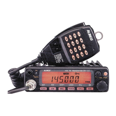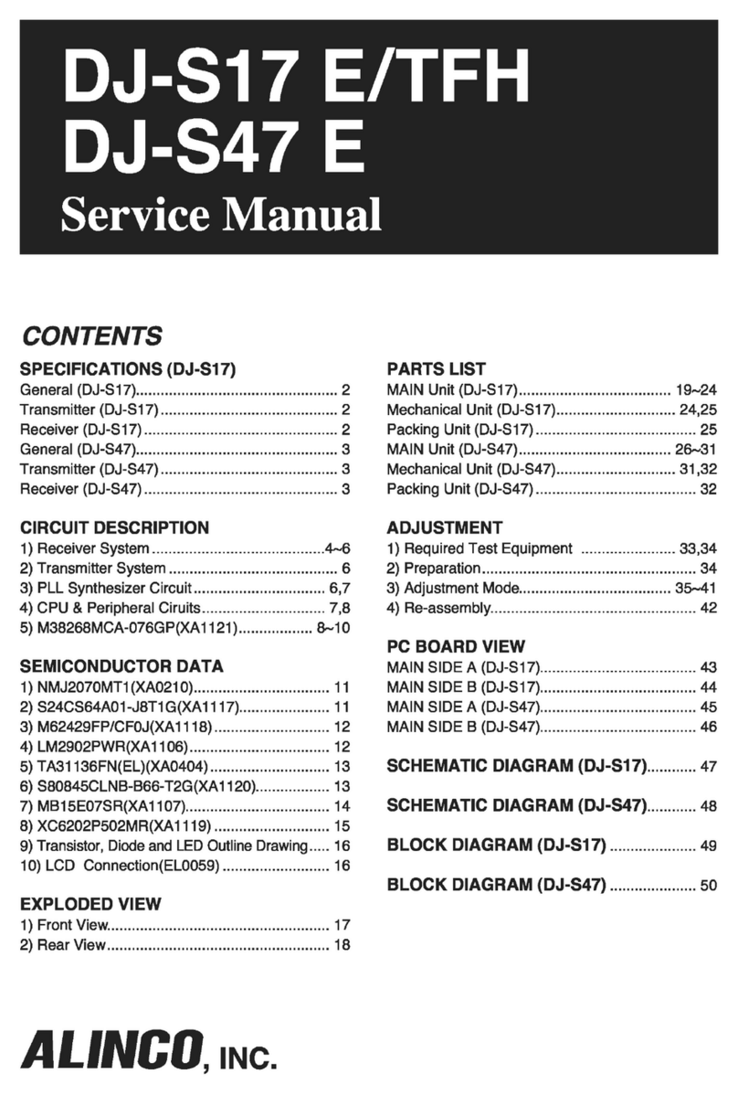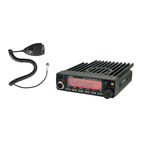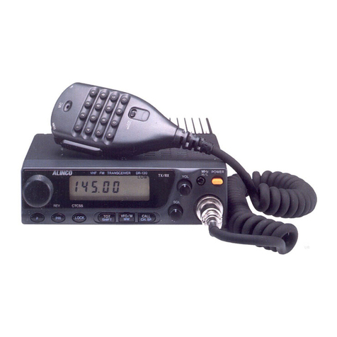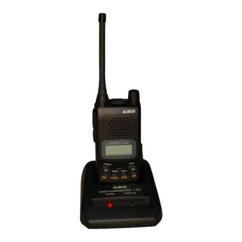
DR-135
Service Manual
CONTENTS
SPECIFICATIONS
1) GENERAL ................................................................ 2
2) TRANSMITTER ........................................................ 2
3) RECEIVER ............................................................... 2
CIRCUIT DESCRIPTION DR-135
1) Receiver System .................................................. 3, 4
2) Transmitter System............................................... 4, 5
3) PLL Synthesizer Circuit ........................................ 5, 6
4) CPU and Peripheral Circuits ................................. 6, 7
5) Power Supply Circuit................................................. 7
6) M3826M8L***GP (XA0795) ............................... 8~10
SEMICONDUCTOR DATA
1) M5218FP (XA0068)................................................ 11
2) NJM7808FA (XA0102)............................................ 11
3) TC4S66F (XA0115) ................................................ 11
4) TK10930VTL (XA0223) .......................................... 12
5) BU4052BF (XA0236) .............................................. 13
6) TC4W53FU (XA0348) ............................................ 13
7) M64076GP (XA0352) ............................................. 14
8) LA4425A (XA0410)................................................. 15
9) M67746 (XA0412) .................................................. 15
10) µPC2710T (XA0449) .............................................. 16
11) NJM2902 (XA0596) ................................................ 16
12) 24LC32A (XA0604) ................................................ 17
13) S-80845ALMP-EA9-T2 (XA0620) ........................... 17
14) L88MS05TLL (XA0675).......................................... 17
15) Transistor, Diode, and LED Ontline Drawings ......... 18
16) LCD Connection (TTR3626UPFDHN) ................... 18
EXPLODEDVIEW
1) Top and FrontView ................................................. 19
2) Bottom View ........................................................... 20
3) LCD Assembly........................................................ 21
PARTS LIST
CPU.................................................................. 22, 23
DSUB ..................................................................... 23
Main Unit .......................................................... 23~26
Mechanical Parts .................................................... 26
Packing Parts ......................................................... 26
Speaker .................................................................. 27
TNC .................................................................. 27, 28
TNC (EJ-41U) Mechanical Parts ............................ 28
TNC (EJ-41U) Packing Parts .................................. 28
ADJUSTMENT
1) Adjustment Spot .................................................... 29
2) VCO and RX Adjustment Specification................... 30
3) Tx Adjustment Specification ................................... 30
4) RxTest Specification............................................... 31
5) TxTest Specification ............................................... 32
PC BOARDVIEW
1) CPU Unit Side A (UP 0400).................................... 33
2) CPU Unit Side B (UP 0400).................................... 33
3) Main Unit Side A (UP 0400).................................... 34
4) Main Unit Side B (UP 0400).................................... 34
5)
Tnc Unit Side A (UP 0402) (DR-135TP only).................
35
6)
Tnc Unit Side B (UP 0402) (DR-135TP only).................
35
SCHEMATIC DIAGRAM
1) CPU Unit ................................................................ 36
2) Main Unit ................................................................ 37
3) TNC Unit (DR-135TP only) ..................................... 38
BLOCK DIAGRAM ..................................................... 39
ALINCO,INC.

