Crin Aprisa 4RF Technical specifications

FICHA TECNICA DE:
RADIO APRISA 4RF
Product Description

2|
Aprisa SR Product Description
Compliance General
The Aprisa SR digital radio predominantly operates within frequency bands that require a site license be
issued by the radio regulatory authority with jurisdiction over the territory in which the equipment is
being operated.
It is the responsibility of the user, before operating the equipment, to ensure that where required the
appropriate license has been granted and all conditions attendant to that license have been met.
Changes or modifications not approved by the party responsible for compliance could void the user’s
authority to operate the equipment.
Equipment authorizations sought by 4RF Communications are based on the Aprisa SR radio equipment
being installed at a fixed location and operated in point-to-multipoint mode within the environmental
profile defined by EN 300 019, Class 3.4. Operation outside these criteria may invalidate the
authorizations and / or license conditions.
The term “Radio” with reference to the Aprisa SR User Manual, is a generic term for one end station of a
point-to-multipoint Aprisa SR network and does not confer any rights to connect to any public network or
to operate the equipment within any territory.
Compliance ETSI
The Aprisa SR radio is designed to comply with the European Telecommunications Standards Institute
(ETSI) specifications as follows:
Radio performance EN 300 113-2
EMC EN 301 489 Parts 1 & 5
Environmental EN 300 019, Class 3.4
Safety EN 60950-1:2006
Frequency band Channel size Power input Notified
body
136-174 MHz 12.5 kHz 12 VDC
400-470 MHz 12.5 kHz 12 VDC

| 3
Aprisa SR Product Description
RF Exposure Warning
WARNING:
The installer and / or user of Aprisa SR radios shall ensure that a separation distance
as given in the following table is maintained between the main axis of the terminal’s
antenna and the body of the user or nearby persons.
Minimum separation distances given are based on the maximum values of the
following methodologies:
1. Maximum Permissible Exposure non-occupational limit (B or general public) of
47 CFR 1.1310 and the methodology of FCC’s OST/OET Bulletin number 65.
2. Reference levels as given in Annex III, European Directive on the limitation of
exposure of the general public to electromagnetic fields (0 Hz to 300 GHz)
(1999/519/EC). These distances will ensure indirect compliance with the
requirements of EN 50385:2002.
Frequency (MHz) Maximum Power
(dBm) Maximum Antenna
Gain (dBi) Minimum Separation
Distance
(m)
136 + 37 15 2.5
174 + 37 15 2.5
330 + 37 15 2.5
400 + 37 15 2.5
470 + 37 15 2.3
520 + 37 15 2.2
850 + 37 28 7.7
960 + 37 28 7.2

Contents | 5
Aprisa SR Product Description
Contents
1. Introduction................................................................................7
The 4RF Aprisa SR Radio......................................................................... 7
Product Overview ................................................................................ 8
Network Coverage and Capacity ........................................................ 8
Remote Messaging......................................................................... 8
Repeater Messaging....................................................................... 9
Product Features................................................................................10
Functions ..................................................................................10
Performance ..............................................................................10
Usability ...................................................................................10
Architecture......................................................................................11
Security...........................................................................................12
Interfaces.........................................................................................13
Antenna Interface........................................................................13
Ethernet Interface .......................................................................13
USB Interfaces ............................................................................13
RS-232 Interface..........................................................................13
Product Options .................................................................................14
Dual Antenna..............................................................................14
Mounting..........................................................................................15
DIN Rail Mounting ........................................................................15
Rack Shelf Mounting .....................................................................16
Wall Mounting.............................................................................17
2. Specifications............................................................................ 18
RF Specifications ................................................................................18
ETSI Compliant............................................................................18
Frequency Bands ..................................................................18
Channel Sizes ......................................................................18
Product Range .....................................................................18
Transmitter.........................................................................19
Receiver ............................................................................19
Modem ..............................................................................20
Data Payload Security ............................................................20
Interface Specifications ........................................................................21
Ethernet Interface .......................................................................21
RS-232 Asynchronous Interface.........................................................21
Power Specifications............................................................................22
Power Supply..............................................................................22
Power Consumption......................................................................22
Power Dissipation ........................................................................22
General Specifications..........................................................................23
Environmental ............................................................................23
Mechanical ................................................................................23
ETSI compliance..........................................................................23

6| Contents
Aprisa SR Product Description
3. Management ............................................................................. 25
SuperVisor........................................................................................25
Viewing the Aprisa SR Terminal Settings..............................................25
Configuring the Aprisa SR Terminal Details...........................................26
Configuring the Aprisa SR RF Network Details .......................................26
Configuring the Aprisa SR Radio Settings .............................................27
Command Line Interface.......................................................................28
Management Display Panel.....................................................................29
LED Display Panel ...............................................................................30
Normal Operation ........................................................................30
Software Upgrade ........................................................................30
Test Mode .................................................................................31
4. Applications.............................................................................. 32
Basic point-to-multipoint application........................................................32
Advanced point-to-multipoint application with repeater .................................33
Multi-interface point-to-multipoint application ............................................34
5. Architecture ............................................................................. 35
Product Description.............................................................................35
Frame ......................................................................................35
MAC Header ........................................................................35
Network Header ...................................................................36
Payload ....................................................................................36
Auxillary Frame...........................................................................36
Physical Layer.............................................................................37
Data Link Layer / MAC layer............................................................37
Channel Access ....................................................................37
Hop by Hop Transmission.........................................................37
Network Layer ............................................................................38
Packet Routing.....................................................................38
Product Operation...............................................................................39
Carrier Sense Disabled...................................................................39
Carrier Sense Enabled ...................................................................40
Product Architecture ...........................................................................43
Radio Block Diagram.....................................................................44
Modem Block Diagram ...................................................................44
6. Contact Us................................................................................ 45
Introduction | 7
Aprisa SR Product Description
1. Introduction
The 4RF Aprisa SR Radio
The 4RF Aprisa SR is a point-to-multipoint digital radio providing secure narrowband wireless data
connectivity for SCADA, infrastructure and telemetry applications.
The radios carry a combination of serial packet data and Ethernet data between the Base Station,
Repeater Stations and Remote Stations.
The Aprisa SR is configurable as a point-to-multipoint Base Station, a Remote Station or a Repeater
Station.

8| Introduction
Aprisa SR Product Description
Product Overview
Network Coverage and Capacity
In a simple point-to-multipoint network, an Aprisa SR, configured as a base station, will communicate with
multiple remote units in a given coverage area. With a link range of up to 60 km a typical deployment will
have 30 – 50 remote stations attached to the base station. However, geographic features, such as hills,
mountains, trees and foliage, or other path obstructions, such as buildings, tend to limit radio coverage.
Additionally, geography may reduce network capacity at the edge of the network where errors may occur
and require retransmission. However, the Aprisa SR uses Forward Error Correction (FEC) which greatly
improves the sensitivity performance of the radio resulting in less retries and minimal reduction in
capacity.
Ultimately, the overall performance of any specific network will be defined by a range of factors including
the geographic location, the number of remote stations in the base station coverage area and the traffic
profile across the network. ). Effective network design will distribute the total number of remote stations
across the available base stations to ensure optimal geographic coverage and network capacity.
Remote Messaging
Base stations are fitted with omni-directional antennas and the remote stations use directional Yagi
antennas for higher gain. On start-up the base station transmits a registration message which is recognised
by the remote stations which respond with their own registration message. This allows the base station to
record the details of all the remote stations active in the network.
There are two message types in the Aprisa SR network, broadcast messages and unicast messages.
Broadcast messages are transmitted by the base station to the remote stations and unicast messages are
transmitted by the remote station to the base station.
All the remote stations, within the coverage area, will receive the messages broadcast from the base
station, but only the radio the message is intended for will action the message. Only the base station can
receive the unicast messages transmitted from the remote station. Unicast messages are ignored by other
remote stations which may be able to receive them. The Aprisa SR network is not designed for remote
stations to communicate with other remote stations.

Introduction | 9
Aprisa SR Product Description
Repeater Messaging
The Aprisa SR uses a routed protocol throughout the network whereby messages contain source and
destination addresses. Upon registration, the radios populate an internal neighbor table to identify the
radios in the network. The remote stations will register with a base station, or a repeater, and the
repeater registers with a base station. In networks with a repeater, the repeater must register with the
base station before the remotes can register with the repeater.
Additionally, all messages contain a ‘message type’ field in the header and messages are designated as
either a ‘broadcast’ message, originating from a base station, or a ‘unicast’ message, originating from a
remote station.
In a network with a repeater, or multiple repeaters, the base station broadcasts a message which contains
a message type, a source address and a destination address. The repeater receives the message and
recognizes it is a broadcast message, from the message type and source address and re-broadcasts the
message across the network. All remote stations in the coverage area will receive the message but only
the radio with the destination address will act upon the message.
Similarly, the remote station will send a unicast message which contains a message type (unicast) a source
address and a destination address (the base station). The repeater will receive this message; recognize
the message type and source address and forward it to the destination address.
It is this methodology which prevents repeater-repeater loops. If there is repeater (A) which, in some
circumstances, is able to pick up the RF signal from another repeater (B), it will not forward the message
as it will only forward broadcast messages from the base station (recognised by the source address). For
unicast messages the repeater (A) will recognize that the message (from repeater (B)) is not from a
remote with which it has an association and similarly ignore the message.

10 | Introduction
Aprisa SR Product Description
Product Features
Functions
•Point-to-Point (PTP) or Point-to-Multipoint (PMP) operation half duplex
•Licensed frequency bands:
VHF 136-174 MHz
UHF 330-400 MHz †
UHF 400-470 MHz
UHF 450-520 MHz†
UHF 850-960 MHz†
•Channel sizes: 6.25 kHz†
12.5 kHz
25 kHz†
•Typical deployment of 30 Remote Stations from one Base Station with a practical limit of a few
hundred Remote Stations.
•Dual antenna option for external duplexers or filters (half duplex operation)
•Ethernet data interface plus RS-232 asynchronous data interface.
•Data encryption and authentication.
•Complies with international standards, including ETSI RF, EMC, safety and environmental
standards.
†Future Product Release
Performance
•Long distance operation (typically 30 km radius).
•High transmit power.
•Low noise receiver.
•Forward Error Correction.
•Electronic tuning over the frequency band.
•Thermal management for high power over a wide temperature range.
Usability
•Configuration / diagnostics via front panel Management Port USB interface, Ethernet interface.
•Remote station configuration / diagnostics over the radio link.
•LED display for on-site diagnostics.
•Optional management display for advanced on-site configuration.
•Firmware upgrade and diagnostic reporting via the Host Port USB flash drive.
•Simple installation with integrated mounting holes for wall, DIN rail and rack shelf mounting.

Introduction | 11
Aprisa SR Product Description
Architecture
The Aprisa SR Architecture is based around a layered TCP/IP protocol stack:
•Physical
Proprietary wireless
Standard RS-232 and Ethernet
•Link
Proprietary wireless (channel access, ARQ, segmentation)
Standard Ethernet
•Network
Standard IP
Proprietary automatic radio routing table population algorithm
•Transport
Standard TCP, UDP
•Application
Proprietary management application software

12 | Introduction
Aprisa SR Product Description
Security
The Aprisa SR provides security features to implement the key recommendations for industrial control
systems. The security provided builds upon the best in class from multiple standards bodies, including:
•IEC/TR 62443 (TC65) “Industrial Communications Networks – Network and System Security”.
•IEC/TS 62351 (TC57) “Power System Control and Associated Communications – Data and
Communication Security”.
It also adds additional security features through Layer 3 network integration.
The security features implemented are:
•Licensed radio spectrum protects against interference.
•Proprietary physical layer protocol and modified MAC layer protocol based on standardized IEEE
802.15.4.
•Data payload security:
CCM Counter with CBC-MAC integrity (NIST special publication 800-38C).
•Data encryption:
Counter Mode Encryption (CTR) using Advanced Encryption Standard (AES).
•Data authentication:
Cipher Block Chaining Message Authentication Code (CBC-MAC) using Advanced Encryption
Standard (AES).
•Secured management interface protects configuration.
•Address filtering enables traffic source authorization †.
•Distributed Layer 3 firewall protects remote nodes †.
•Segregated traffic flow enables node isolation, with VLAN and Layer 3 subnets †.
†Future Product Release

Introduction | 13
Aprisa SR Product Description
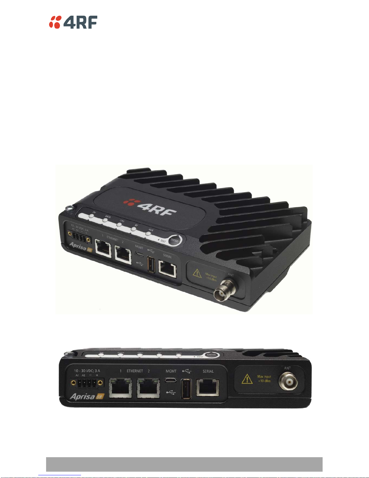
Interfaces
Antenna Interface
•1 x TNC, 50 ohm, female connector
Single Antenna Option
•2 x TNC, 50 ohm, female connectors
Dual Antenna Option
Ethernet Interface
•2 x ports 10/100 base-T Ethernet layer 2 switch using RJ-45.
Used for Ethernet user traffic and product management.
USB Interfaces
•1 x Management Port using USB micro type B connector.
Used for product configuration with the Command Line Interface (CLI).
•1 x Host Port using USB standard type A connector.
Used for software upgrade and diagnostic reporting.
RS-232 Interface
•1x RS-232 asynchronous port using RJ-45 connector.
Used for RS-232 async user traffic only.
14 | Introduction
Aprisa SR Product Description
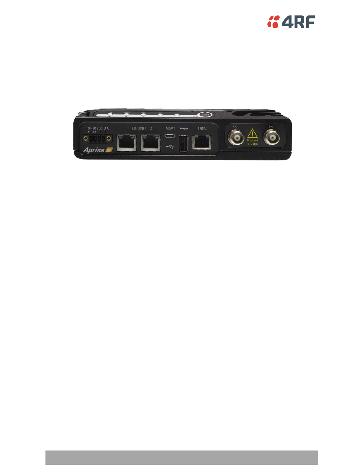
Product Options
DualAntenna
The standard Aprisa SR uses a one or two frequency ½ duplex transmission mode which eliminates the
need for a duplexer. However, a Dual Antenna option is available for separate transmit and receive
antenna connection to support external duplexers or filters. The transmission remains half duplex.
Antenna Option Part Number
Single Antenna APSR-N400-012-SO
Dual Antenna
-12-ETAA
APSR-N400-012-DO
-12-ETAA

Introduction | 15
Aprisa SR Product Description
Mounting
The Aprisa SR has four threaded holes (M4) in the enclosure base and two holes (5.2 mm) through the
enclosure for mounting.
Mounting options include:
•DIN rail mounting with the Aprisa SR DIN Rail Mounting Bracket
•Rack shelf mounting
•Wall mounting
•Outdoor enclosure mounting
DIN Rail Mounting
The Aprisa SR has an optional accessory part ‘4RF Aprisa SR Acc, Mounting, Bracket, DIN Rail’.
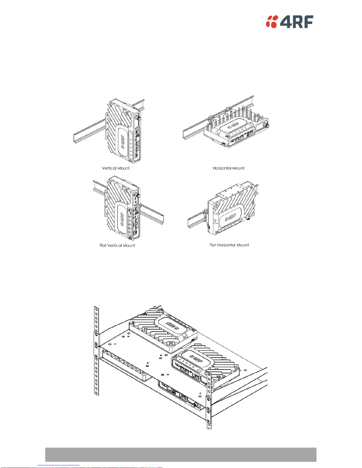
16 | Introduction
Aprisa SR Product Description
The Aprisa SR DIN rail mounting bracket can be mounted in four positions on a horizontal DIN rail:
•Vertical Mount (vertical enclosure perpendicular to the mount)
•Horizontal Mount (horizontal enclosure perpendicular to the mount).
•Flat Vertical Mount (vertical enclosure parallel to the mount)
•Flat Horizontal Mount (horizontal enclosure parallel to the mount)
Rack Shelf Mounting
The Aprisa SR can be mounted on a rack mount shelf using the four M4 threaded holes in the Aprisa SR
enclosure base. The following picture shows Aprisa SR mounted on 1 RU rack mounted shelves.
Introduction | 17
Aprisa SR Product Description
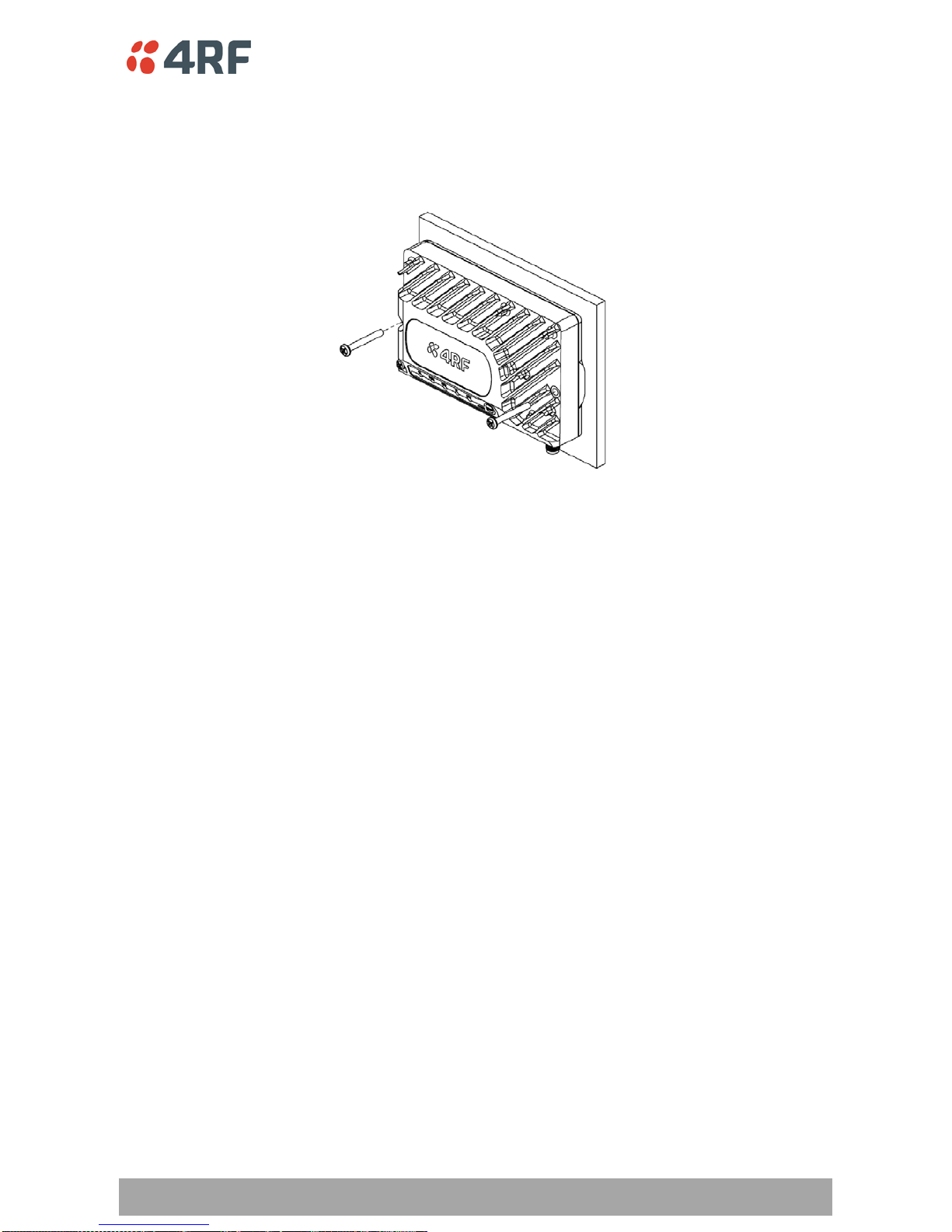
Wall Mounting
The Aprisa SR can be mounted on a wall using the two holes through the enclosure (5.2 mm diameter).
Typically, M5 screws longer than 35 mm would be used.
18 | Specifications
Aprisa SR Product Description
2. Specifications
RF Specifications
ETSI Compliant
Frequency Bands
Broadcast Band Frequency Band Frequency Tuning
Range Synthesizer Step
Size
VHF 136 MHz 136-174 MHz 3.125 kHz
UHF 330 MHz †330-400 MHz 6.250 kHz
UHF 400 MHz 400-470 MHz 6.250 kHz
UHF 450 MHz †450-520 MHz 6.250 kHz
UHF 900 MHz †850-960 MHz 6.250 kHz
Channel Sizes
Channel Size Gross Radio Capacity
6.25 kHz †4.8 kbit/s
12.5 kHz 9.6 kbit/s
25 kHz †19.2 kbit/s
†Future Product Release
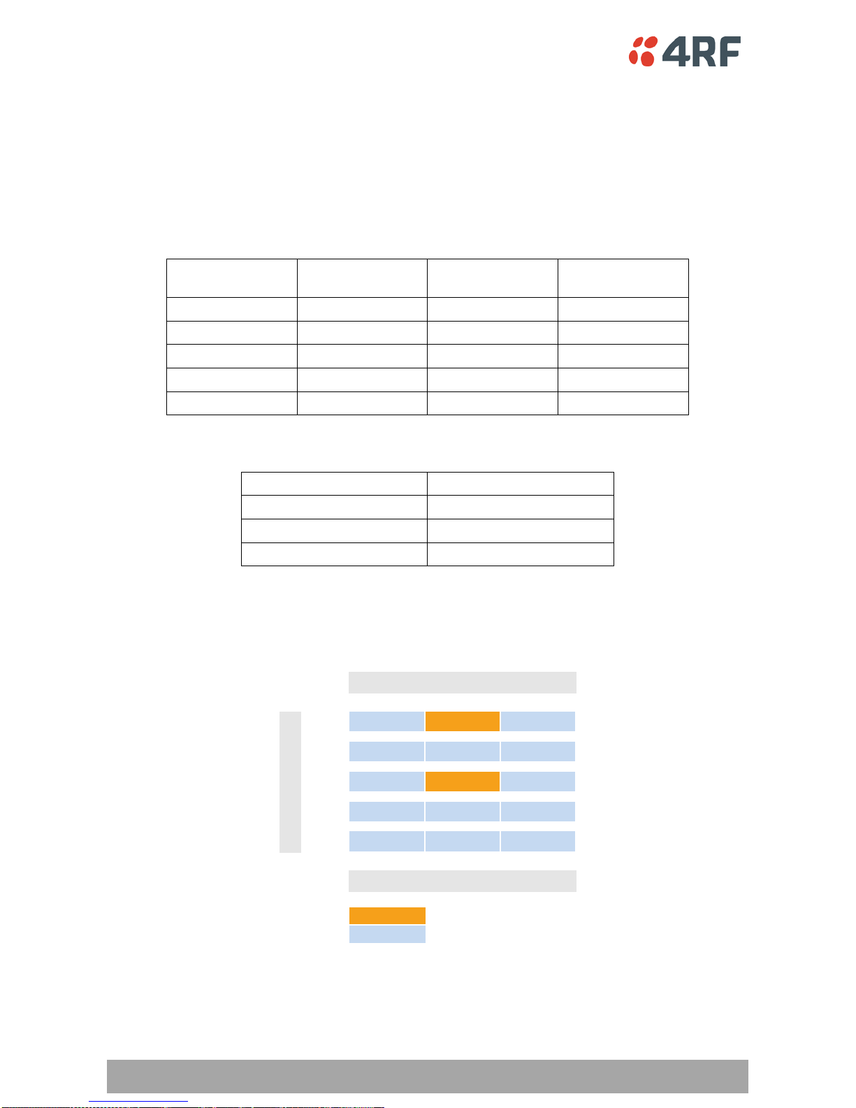
Product Range
6.25 12.5 25
136
330
400
450
900
4.8 9.6 19.2
CurrentProductRelease
Future ProductRelease
Frequency Band (MHz)
Gross Radio capacity(kbit/s)
Channel Size (kHz)
Specifications | 19
Aprisa SR Product Description
Transmitter
Power output 0.1 to 5.0 W (+20 to +37 dBm, in 1 dB steps)
Adjacent channel power < - 60 dBC
Transient adjacent channel power < - 50 dBC
Spurious emissions < - 37 dBm
Attack time < 1.5 ms
Release time < 1.5 ms
Data turnaround time < 10 ms
Frequency stability ± 1 ppm
Frequency aging < 1 ppm / annum
Synthesizer lock time < 1.5 ms (5 MHz step)
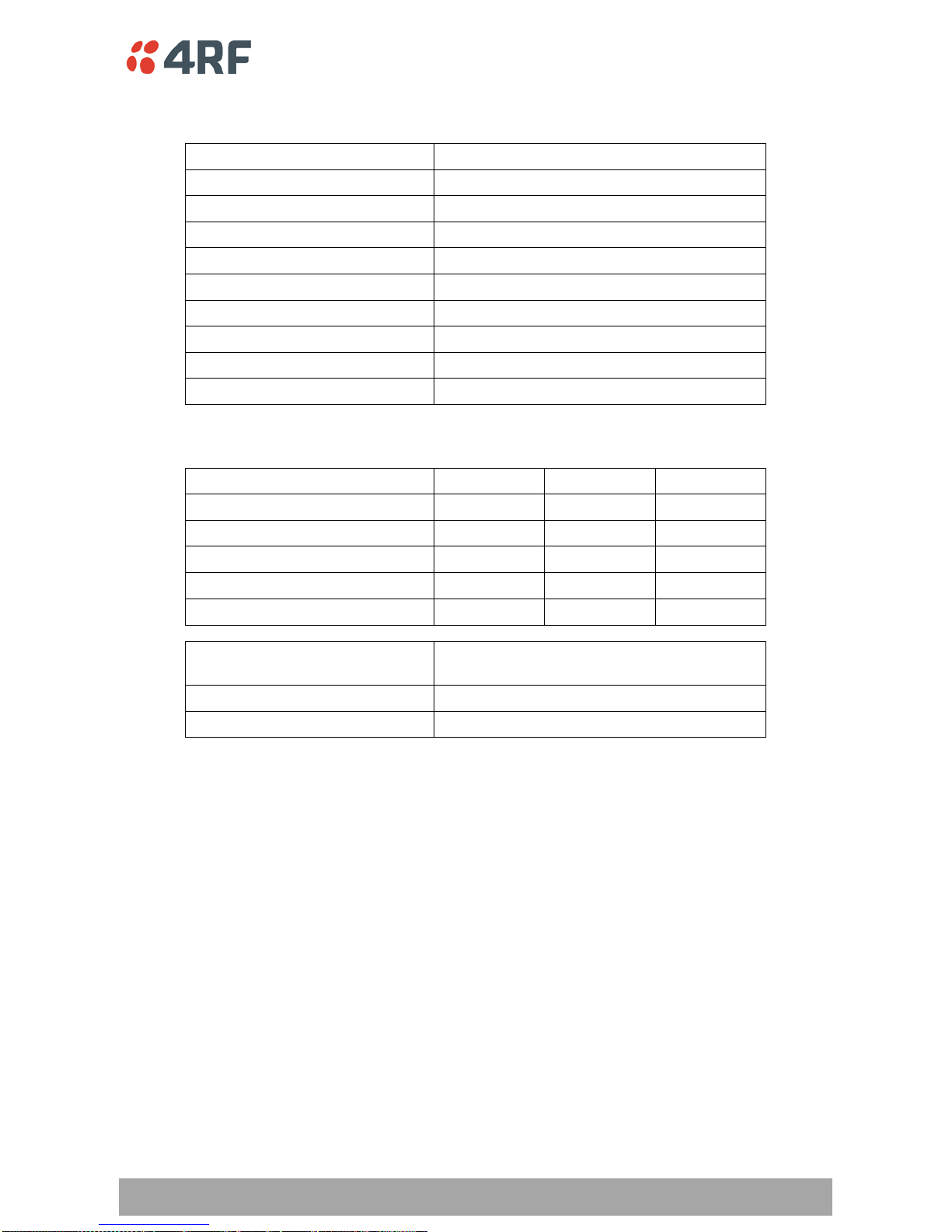
Receiver
6.25 kHz †12.5 kHz 25 kHz †
Receiver Sensitivity BER < 10-2 –119 dBm –117 dBm –114 dBm
BER < 10-3 –114 dBm
BER < 10-6 –110 dBm
Adjacent Selectivity > 60 dB > 60 dB > 70 dB
Co-channel rejection > –12 dB
Intermodulation response
rejection > 70 dB
Blocking or desensitization > 84 dB
Spurious response rejection > 75 dB

20 | Specifications
Aprisa SR Product Description
Modem
Modulation 4-CPFSK
Forward Error Correction ¾ Trellis code
Data Payload Security
Data payload security CCM* Counter with CBC-MAC
Data encryption Counter Mode Encryption (CTR) using Advanced
Encryption Standard (AES) 128, 192 or 256
Data authentication Cipher Block Chaining Message Authentication
Code (CBC-MAC) using Advanced Encryption
Standard (AES) 128, 192 or 256
†Future Product Release
Table of contents


