Cromptons Wheel Of Fortune User manual


920847 Wheel Of Fortune 2
1 PLAYER WHEEL OF FORTUNE
OPERATOR’S MANUAL
Machine Part Number: 920847
Manual Part Number: 990510 Issue 1
© 2004 Cromptons Leisure International Ltd
All Rights Reserved
No part of this publication may be reproduced in any form without the
written permission of Cromptons Leisure International Limited.
Every effort has been made to ensure that the information contained in
this manual is accurate. Cromptons Leisure International Limited reserve the
right to make alterations without prior notice.
Cromptons Leisure International Limited
4 Wilton Road, Haine Industrial Estate, Ramsgate, Kent
CT12 5HG. UK
Tel: +44 1843 593335 Fax: +44 1843 588043 www.cromptons.com

920847 Wheel Of Fortune 3
List of Contents
1. Introduction
1.1 Warnings, Cautions and Notes 5
1.2 Safety Precautions 5
1.3 Abbreviations and Terms 5
2. Game play & Description
2.1 Game play & Description 6
2.2 Game play 7
2.3 Navigation Front 8
2.4 Navigation Back 9
2.5 Navigation Top Sign 10
3. Installation & Setup
3.1 Installation 11
3.2 Setting-up the Playfield with Coins 11
3.3 Pre-Operation Checks 11
4. Security
4.1 Tilt Bob 12
4.2 Intelligent Tilt 13
4.2 Slam Tilt 13
5. Programmer & Dipswitch Settings
5.1 Sound PCB & Dip Switch Settings 14
5.2 Main Control PCB - General 15
5.3 Main Control PCB – Dipswitch 15
5.4 Main Control PCB – Dipswitch SW1 16
5.5 Main Control PCB – Dipswitch SW2 16
6. Ticket Refill
6.1 Refill Ticket Routine 17
7. Routine Maintenance16
7.1 Daily Inspection 18
7.a PSU Rack Checks 19
7.b Fluorescent Lamp replacement 20
7.c Coin Entry Check 21
7.d Playfield 21
7.e Pin Perspex Removal 22
7.f Back Door Removal 23
7.g Payout Level 24
7.h Lock Replacement 25
8. Electrical Wiring Schematic 26
9. Parts List 27

920847 Wheel Of Fortune 4
1. IT IS ESSENTIAL THAT ONLY SUITABLY QUALIFIED
PERSONNEL CARRY OUT MAINTENANCE AND REPAIR
OPERATIONS.
2. TO PREVENT INJURY AND ELECTRIC SHOCK, SWITCH OFF
AND DISCONNECT ALL ELECTRICAL POWER SUPPLIES
BEFORE OPENING DOORS AND PANELS AND STARTING
WORK ON THE MACHINE.
3. TO PREVENT ELECTRIC SHOCK DURING OPERATION, A
SECURE, GROUNDED ELECTRICAL PLUG MUST BE FITTED.
4. USE ONLY THE SPECIFIED ELECTRICAL FUSES SHOWN IN
THE PARTS LIST. REPLACEMENT FUSES MUST MATCH
THOSE TO BE REPLACED IN FUSE TYPE AND RATING. THE
FUSE COVER (WHERE APPLICABLE) MUST BE IN PLACE
BEFORE SWITCHING THE MACHINE ON.
5. TO MAINTAIN THE SAFE AND EFFICIENT OPERATION OF
THE MACHINE, USE ONLY PARTS THAT HAVE BEEN
SUPPLIED BY CROMPTONS, OR ARE CROMPTONS
APPROVED.
6. THIS MACHINE IS INTENDED FOR INDOOR USE ONLY.
CAUTION
1. MANY ELECTRICAL PLUGS ARE KEYED TO FIT ONE WAY.
NOTE ORIENTATION BEFORE REMOVAL.
2. BEFORE HANDLING A PCB OR ITS COMPONENT PARTS,
TAKE FULL ANTI-STATIC PRECAUTIONS.
3. WAIT FOR AT LEAST ONE MINUTE AFTER SWITCHING THE
MACHINE OFF, TO ENABLE THE CAPACITORS TO FULLY
DISCHARGE BEFORE SWITCHING BACK ON. FAILURE TO
DO SO MAY RESULT IN A LOSS OF FUNCTIONALITY.

920847 Wheel Of Fortune 5
Introduction
This manual is intended to act as a guide to the operation of the machine.
The list of contents shows the layout of the manual. Should repairs be
necessary, there is a Parts List of components that are normally
considered replaceable. Recommendations are made throughout the
manual and it is essential that these be followed for safety reasons.
1.1 Warnings, Cautions and Notes
“WARNING”: refers to essential safety precautions that must be taken to avoid
a potential hazard to health.
“CAUTION”: refers to precautions that must be taken to avoid damage to the
equipment.
“NOTE”: refers to advisory information, normally to assist in performing
tasks.
1.2 SAFETY PRECAUTIONS
The following general Safety Precautions apply to all Operators and Engineers
and must be complied with at all times. More specific warnings and cautions
are also provided in the manual where they apply.
1.3 Abbreviations and Terms
Units used are the standard SI units, e.g. grams “g”, volts “V”, etc
Abbreviations
Assy. Assembly
CW Clockwise
DIP Dual In-line Package
EMC Electro Magnetic Compatibility.
GRP Glass Reinforced Plastic.
ICE Innovative Concepts in Entertainment
JST Japanned Solderless Terminal
LED Light Emitting Diode.
PCB Printed circuit board.
PSU Power supply unit.
TBD To be done.
LH Left Hand
RH Right Hand
Terms
Coin Coin or Token
Fixings Small pieces of metalwork, etc used for assembly
Slug Counterfeit coin or token

920847 Wheel Of Fortune 6
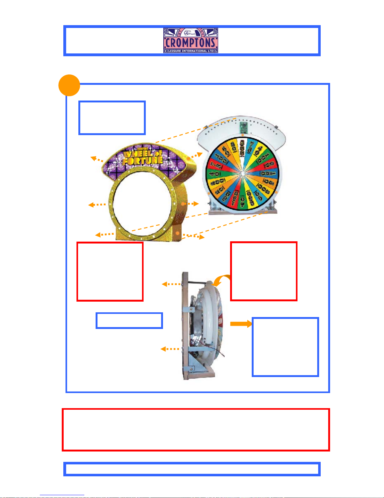
2.0 GAME PLAY & DESCRIPTION
Figure 1- General View of Wheel of Fortune
2.1 General Description
The Wheel of Fortune can be divided into 4 separate levels as shown in Figure 1
Each level contains assembly of components that at times may require
adjustments and maintenance.
Marquee Level
Coin Entry Level
Playfield Level
Payout Level

920847 Wheel Of Fortune 7
2.2
1
Drop Quarter or Token
down the Skill Arm.
2
Use the Button to stop
the arm and direct the coin.
Time the drop with the running
lights.
3
Each time a running light is
hit a WHEEL OF FORTUNE letter
is lit.
GAME PLAY
4
When all 14 letters
are lit the bonus wheel
s
p
ins for extra tickets
5
The Quarter or Token
continues to the playfield and
pushes coins forward towards
6
When coins fall over the edge,
tickets are paid to the player.

920847 Wheel Of Fortune 8
Marquee Assembly
Coin Entry Door
Pin Perspex Assy
Edge Win Count Module
Pusher Box Assy
Skill Stop Button
Main Control Board
Ticket Payout
Latch Switch

920847 Wheel Of Fortune 9
PSU Rack Assy LED Bonus Board
LED Bonus Board
Motor Drive Arm Assy
Motor Interlock Switch
Power Supply
Halogen Transformer
Mains Power Filter

920847 Wheel Of Fortune 10
Wheel Perspex
LED Lighting PCB
LED Controller
& Stepper Drive
Card
Stepper Motor
& Fan Ass
y
LED Lighting PCB
TopSign Glitter Coat
Housing

920847 Wheel Of Fortune 11
Installation & Setup
3.1 Installation
i. Remove the machine from the shipping crate and check that it is complete.
Any special instructions and the entry keys are attached to the outer surface of
the machine. Ensure that all transit packing is removed from outside and inside
the machine. Close and lock all doors and panels.
ii. The machine must be installed for use on a stable, level surface. It must not be
exposed to extremes of temperature or high humidity. Ensure that the mains
electrical supply is grounded and complies with the specification shown on the
Identification Label (normally located on the side of the machine). Ensure the
switch on the electrical socket is set to "ON". Connect to the mains electrical
supply using a readily accessible disconnect device, and switch on the supply,
starting the machine. The power switch is located in the payout level of the
machine, (see page 19)
iii. Check that all lights are working and that the pusher box is moving smoothly.
When the machine appears to be functioning correctly, set up the playfields as
follows.
iv. Check that the skill arm is working correctly (see page 7, Game Play)
3.2 Setting-Up the Playfield with Coins
The following set-up procedure is recommended before the machine is played:-
i. To "float-up" the play area, turn the machine on, open the glass access door
and spread approximately 720 coins evenly over the Playfield.
ii. To settle the machine ready for play, feed approximately another 720 coins
evenly onto the playfield through the Coin Entry.
iii. Open the Payout door and fill the Ticket Dispenser.
3.3 Pre-Operation Checks
i. Visually check that the playfield is correctly set up with Coins.
ii. Open the Payout Door and visually check the and Ticket Dispenser is full.
iii. Set the Sound Volume to the desired level (Figures 3).
iv. Feed several Coins into the Coin Slot and visually check that the Coins fall
onto the Playfield correctly.
v. Check that the Coin Entry sound is triggered each time a Coin is entered.
vi. Check the operation of the skill stop arm by pressing the button to stop the
arm.
CAUTION:
DO NOT FILL THE COUNT
HOPPER WITH COINS AS THE
MACHINE WILL PAYOUT
I
NCO
RRE
C
TLY
920847 Wheel Of Fortune 12
4.0 Security
The machine uses three separate tilt mechanisms to enhance security:
The Alarm is a continuous two tone sound that lasts for approximately 8-10
seconds.
The machine is protected by three different tilt mechanisms - the Tilt Bob, the
Slam Tilt and the Intelligent Tilt™. The settings of each can be adjusted to alter
their sensitivity.
Please note that these settings are critical to ensure game play – they must be set
sensitively enough to protect the machine, but if they are set too sensitively, game
play will be adversely affected.
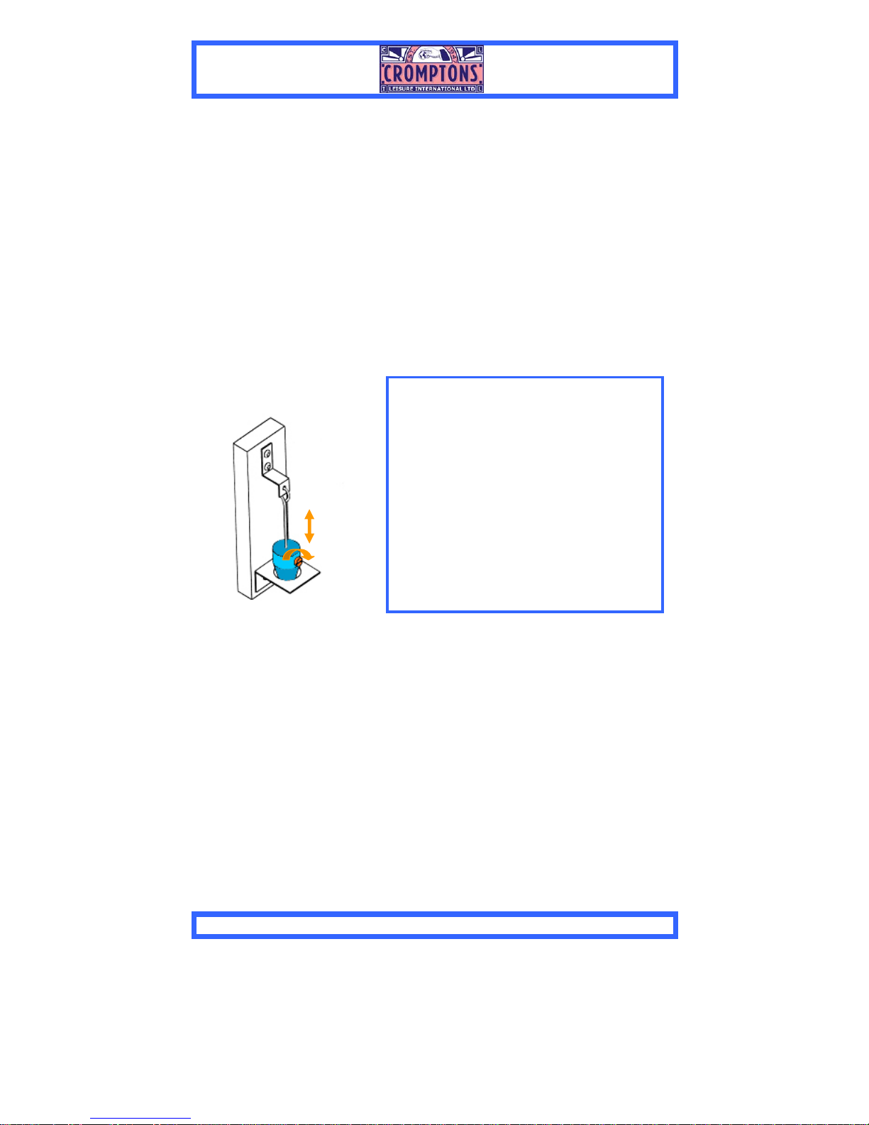
Tilt Bob Mechanism
4.1 TILT BOB MECHANISM ADJUSTMENT.
The Tilt Bob is housed in the coin entry level
of the machine.
It operates under gravity by making contact
between the metal frame and the free-
swinging bob if the machine is tilted beyond a
pre-determined angle.
To set the tilt angle, loosen the Locking
Screw on the side of the bob. The bob can
then be moved up the shaft to increase the
operating angle or down the shaft to decrease
the angle. Ensure that the Locking Screw is
tightened following adjustment.
920847 Wheel Of Fortune 13
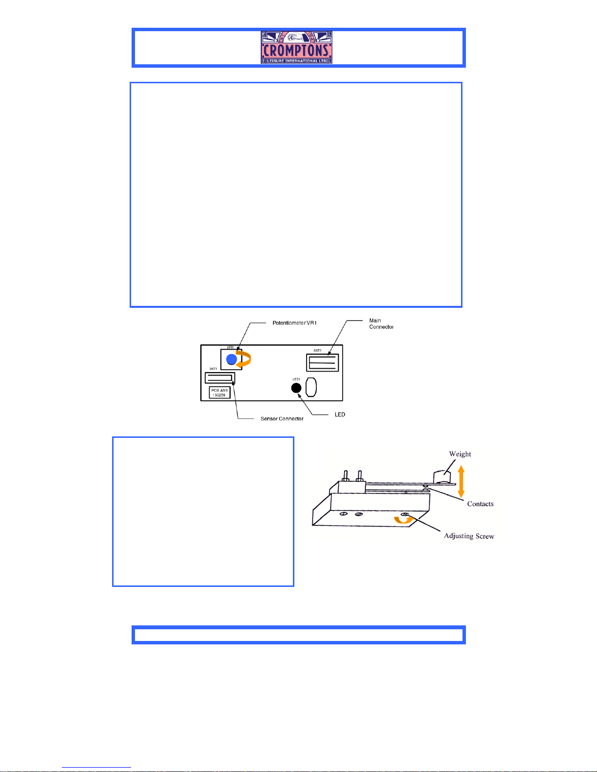
Intelligent Tilt Assembly
4.2 INTELLIGENT TILT™ADJUSTMENT
The piezo-electric sensors and associated PCBs are secured to the underside of the
Win Chutes.
The sensitivity of the Intelligent Tilt mechanism can be adjusted by turning the
potentiometer VR1 on the Intelligent Tilt PCB.
Turning the potentiometer anti-clockwise increases sensitivity, and turning it
clockwise decreases sensitivity.
To test for correct function:
1. Remove the Glass Door from the Play Section.
2. Position a coin at the edge of the Playfield, as far away from the Coin Fall
Detector as possible (to check for maximum sensitivity).
3. Gently push the coin over the edge so that it drops into the win chute, as it
would do in normal play.
4. As the coin enters the win chute, visually check that the LED on the PCB
lights, indicating that the coin has been detected. This will not cause the alarm
to sound.
If the LED does not light, turn the potentiometer anti-clockwise slightly and repeat
the test.
4.3 SLAM TILT ADJUSTMENT
The Slam Tilt Switches comprise an
adjustable switch with a weight mounted on
a sprung arm.
The switch operates if the machine is struck
with enough force to move the weight and
close the electrical contacts
Tightening the Adjusting Screw reduces the
gap between the contacts and makes the
switch more sensitive
920847 Wheel Of Fortune 14
5.0 Programmer & Dipswitch Settings
Sound Card
SW1 SW2 SW3 Time Interval
OFF OFF OFF No attract sound
ON OFF OFF 30 Seconds
OFF ON OFF 60 Seconds
ON ON OFF 90 Seconds
OFF OFF ON 120 Seconds
ON OFF ON 150 Seconds
OFF ON ON 180 Seconds
ON ON ON 210 Seconds
Table 1 "Attract Sound" - Dipswitch Settings
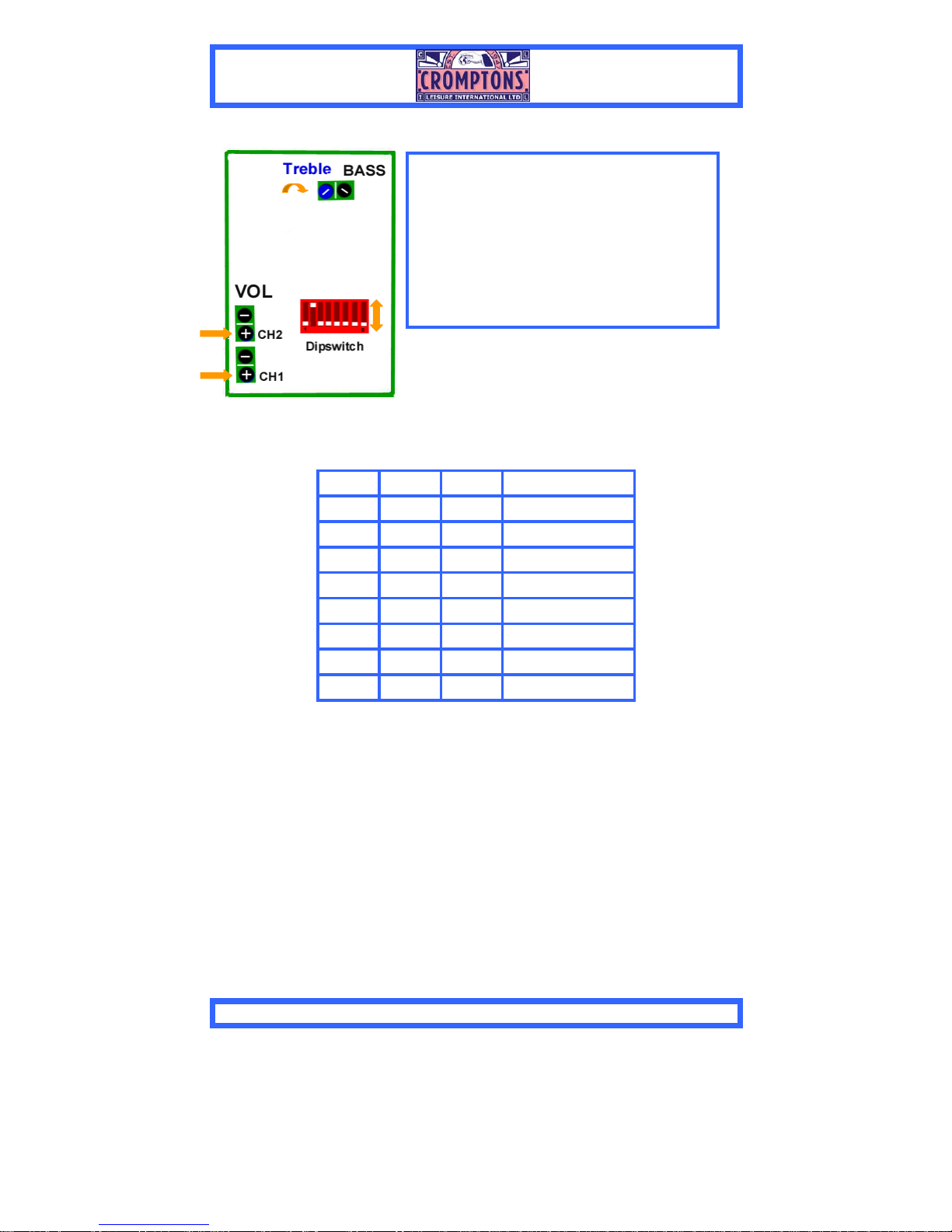
5.1 SOUND PCB –DIPSWITCH SETTINGS
A Dipswitch unit mounted on the Sound
PCB is used to control the “Attract Sound”.
This sound is intended to attract players to
the machine when it is not being played).
The time interval between the sounds is
settable as shown below. Only switches 1 to
3 of the 8 switches are currently used.
920847 Wheel Of Fortune 15
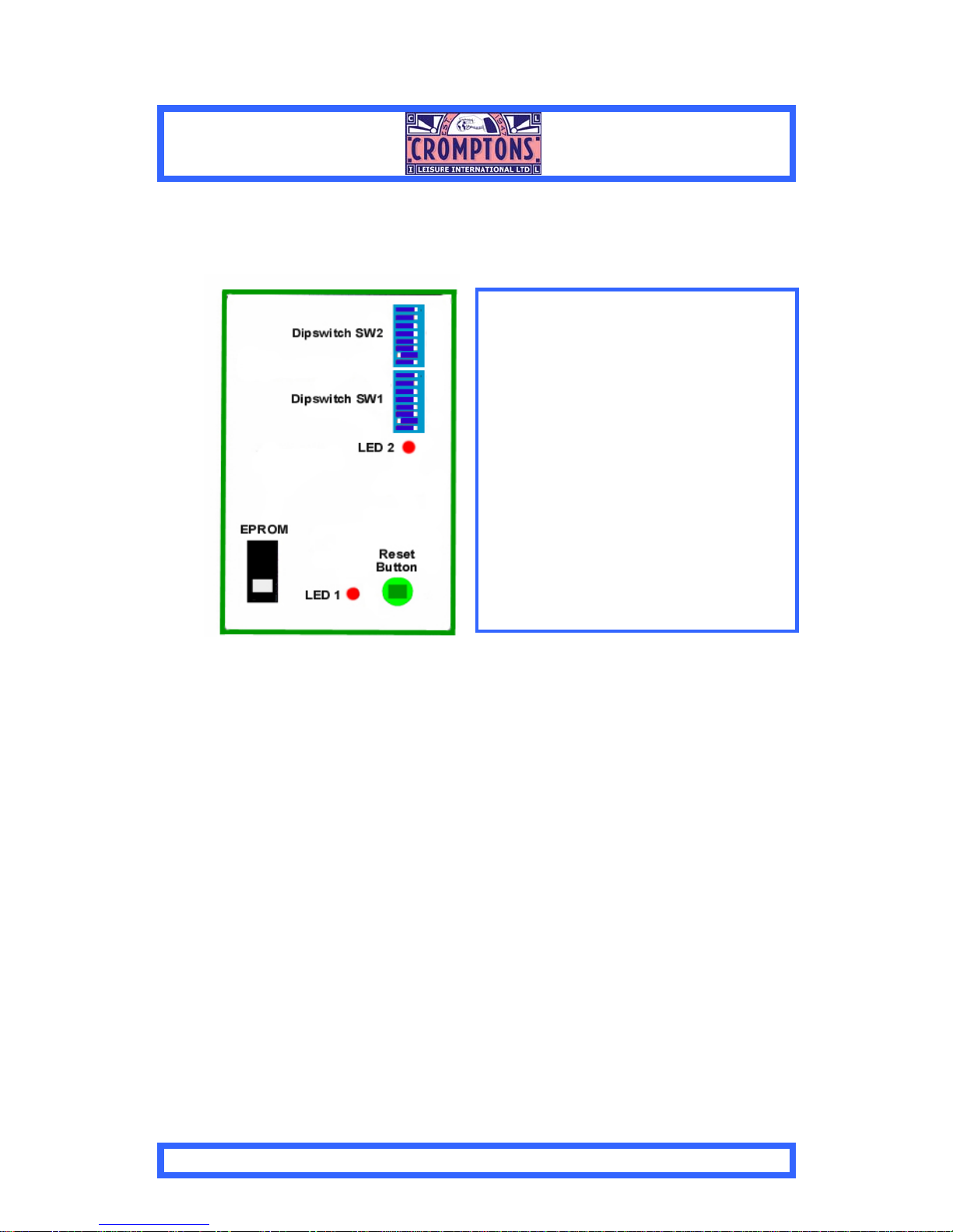
Figure 2 - Control PCB
Pressing the Reset Button resets the control system for that Play Section without
disturbing other parts of the machine. Pressing this button will also cause unpaid
tickets to be paid out following a refill.
5.3 Main Control PCB - Dipswitch Settings
Two banks of Dipswitches are located on each Main Control PCB, labelled
“SW1” and “SW2” (Figure 5). The switches themselves are labelled with the
numbers “1-8” and the ‘ON’ position is shown.
The Dipswitch settings take effect only at Power-up or after the Main Control
PCB Reset button has been pressed.
A Software Specification Sheet is located inside the ticket level of each machine.
This specifies the Dipswitch settings for that particular machine and, in the event
of conflicting information, should be followed in preference to the settings shown
below.
5.2 MAIN CONTROL PCB –GENERAL
A separate Main Control PCB is used to
control each play section. Above each
PCB is a label with its Play Section
number.
Each PCB has two LEDs incorporated:
LED1 is illuminated while there is power
to the PCB.
LED2 is a software monitor that flashes
regularly while the program is running
correctly. If this LED stops flashing at
any time, pressing the Reset Button will
cause the program to be reset.

920847 Wheel Of Fortune 16
5.3 - Dipswitch SW1
DS Default Setting Description
1 +1 ON
2 +2 OFF
Merci Ticket
Adjustment
3 +4 OFF
If all OFF no Merci Ticket is paid.
DS1 ON = 1 Ticket
DS1 & 2 ON = 3 Tickets (cumulative
values)
4 +1 ON
5 +2 OFF
6 +4 ON
Number of
Tickets paid
per coin over
the edge
7 +8 OFF
If all OFF no Tickets paid
DS1 & 6 ON = 5 Tickets paid for each
coin over the edge (cumulative values)
Not Used 8 OFF Not Used
5.4 - Dipswitch SW2
DS Default Setting Description
9 +1 OFF
10 +2 OFF
Feature Ticket
Adjustment
11 +4 ON
Ave tickets from feature per coin in
DS11 ON = Ave 4 tickets per coin in.
12 - OFF Clear Down RAM settings
13 - OFF
14 - OFF
15 - OFF
TEST Modes
16 - OFF
Only used for Test modes please
contact your Distributor
The above default setting will give the following payout:
For every coin in deliver 1 merci ticket, 5 tickets for every coin over the edge
and average 4 tickets for the Wheel of Fortune bonus payout. Effectively this
will total 10 tickets out for every coin in.

920847 Wheel Of Fortune 17
6.0 Filling Ticket Dispenser Versions
Tickets Reload Sequence
An LED visible on the playfield also indicates when Tickets are low. When a
section runs out of tickets, an audio alarm indicates “Tickets Empty.”
To refill ticket bin and pay out any remaining tickets, carry out the following
steps
i. Remove the Payout Door. Place the block of folded tickets in the Ticket
Box so that the feed will be in correct orientation.
ii. Switch the power supply ON (if not already on) and press the advance
button on the side of the dispenser until tickets appear at the Payout Slot.
iii. Tear off any excess tickets and replace the Payout Door. Take care not to
trap the tickets.
iv. The machine verifies tickets are present and pays any tickets owing and
allows the game to be continued.
v. The door switch (see Navigate-Front, page 8) has a pull latch ON state for
testing ticket payout with the door open.
Ticket Low LED

920847 Wheel Of Fortune 18
7.0. Routine Maintenance
Daily Inspection
It is recommended that the following checks are carried out daily:
i. Switch the machine on.
ii. Visually check that the machine is clean inside and out and that all lamps are
working.
iii. Visually check that there are no coins jammed in the Coin Entry.
iv. Check that the playfield is correctly set-up with coins. Do not attempt to
change a playfield which has already been set up.
See Next Page for Details of routine maintenance
WARNING:
1) MAINTENANCE AND REPAIR WORK SHOULD ONLY
BE CARRIED OUT BY SUITABLY SKILLED AND
TRAINED PERSONS.
2) SWITCH OFF AND DISCONNECT ELECTRICAL
POWER SUPPLY BEFORE WORKING ON THE
MACHINE. NOTE THAT MAINS SUPPLY VOLTAGES
ARE USED BEHIND THE COIN ENTRY, THE PAYOUT
AND REAR SERVICE DOORS.
CAUTION:
1) When touching any PCBs or their component parts, take
full anti-static precautions at all times, or else electronic
components may be damaged.
2) Note the orientation of all PCBs and their connectors before
removal, to ensure correct reconnection.
3) After installation or assembly, test any affected parts for
correct function before use.

920847 Wheel Of Fortune 19
PSU Rack Checks
There are no fuses on the main power supply. A circuit breaker is utilised to protect the
machine from surges in supply. To access the switch remove the front door at the payout
level.
The low-voltage Halogen lamps illuminating the playfield are powered from the mains via a
Transformer inside the PSU rack Assy. The Transformer has a Transformer PCB on the
front of the rack, which acts as an interface between the power supply, the Transformer and
the lamps, and is equipped with an anti-surge fuse.
Switch off and disconnect the power supply. Remove the PSU rack from the back of the
machine.
Disconnect the electrical connector from the transformer.
Remove the securing nut and setscrew from the base of the transformer and remove.
Install by reversing the above procedure.
WARNING
To prevent injury, ensure that the Electrical Supply is switched off and disconnected
before changing the main fuse or performing any kind of maintenance task.
Switch the machine ‘ON’.Visually check that the machine is clean inside and out and that
all lamps are working. If the machine does not work check the electrical supply and main
fuses.
A
Anti Surge Fuse
Circuit Breaker
Switch
Halogen
Transform
920847 Wheel Of Fortune 20
Fluorescent Lamp Lighting & Component Replacement
Remove Fixings to
release Front
Moulding
Remove Fixings Release printed
wheel. Replace
Lamps or
Components and
re-assemble in
reverse order.
b.
WARNING
To prevent injury, ensure that the Electrical Supply is switched off and disconnected
before changing the main fuse or performing any kind of maintenance task.
WARNING
Disconnect lamp
loom before
removing front
moulding
WARNING
Ensure that the
LED PCB is clear
before removing
Wheel
Table of contents
Other Cromptons Game manuals

Popular Game manuals by other brands


Hathaway
Hathaway Daulton BG50351 Assembly instructions

Fundex Games
Fundex Games Don't Cut the Cheese instructions

Fundex Games
Fundex Games Chicken Coop User instructions

Learning Resources
Learning Resources Food Pyramid LER 2493 manual

Famosa
Famosa Feber Super 4 in Line quick start guide

Halex
Halex Madison II Owner's manual and instructions

Playcraft
Playcraft AHDB06BK Assembly instructions

Radica Games
Radica Games Rider 9904 instructions

EZI- Mik
EZI- Mik CYBERDINE DART user manual

Handmark
Handmark Scrabble Crossword Game user guide

Hasbro
Hasbro Poppin' Bedbugs Pinball 06102 instruction manual

Rio Grande Games
Rio Grande Games Bohnanza Princes and Pirates manual