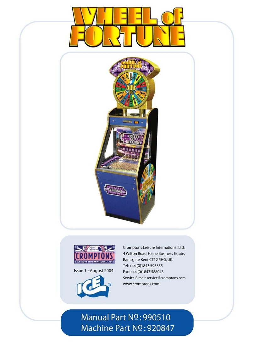
Cromptons Spinna Winna User manual

Spinna Winna Operators Manual Part No. 990xxx Issue 1
Page 1 of 31
•3 PLAYER WITH COIN SHELVES, CHANGER AND NON
CHANGER, MK4 AND MK5 COIN ENTRY SYSTEMS.
•2 PLAYER TICKET PAYOUT WITH COIN SHELVES AND
SLIDING SKILL COIN ENTRY.
4 Wilton Road, Haine Business Park,
Ramsgate, Kent CT12 5HG, United Kingdom
Tel: +44 (0)1843 593335 Fax: +44 (0)1843 588043
www.cromptons.com
E-mail: [email protected]
CROMPTONS
LEISURE INTERNATIONAL LTD

Spinna Winna Operators Manual Part No. 990xxx Issue 1
Page 2 of 31
Page
1. Introduction…………………………………………………………………. 3
1.1. About warnings, Cautions and Notes………………………………….. 3
1.2. Safety Precautions……………………………………………………… 3
1.3. Standard Abbreviations………………………………………..……….. 4
1.4. How to Contact Cromptons Leisure International Ltd…………………. 4
2. Product Overview…………………………………………………………… 5
2.1. Main Features………………………………………………………….. 5
2.2. Description…………………………………………………………….. 5
3. A Step by Step Guide to Setting up your Spinna Winna……………….… 6
4. Troubleshooting……………………………………………………………... 11
5. Maintenance Tasks………………………………………………………….. 14
5.1. Recommended Daily Routine Maintenance……………………………… 14
5.2. Tilt Mechanism Adjustment……………………………………………… 14
5.3. Removing the Top Sign………………………………………………...… 17
5.4. Replacing a Playfield Florescent Lamp………………………………….. 18
5.5. Replacing a Top Sign Florescent Lamp…………………………………. 19
5.6. Replacing a Playfield Halogen Lamp……………………………………. 20
5.7. Replacing a Halogen Fuse or Mains Supply Fuse………………………. 21
5.8. Replacing a Playfield Drive Motor……………………………………… 22
5.9. Accessing/Removing a CDS Unit……………………………………….. 23
5.10. Accessing a sliding coin flipper unit……………………………… 24
5.11. Refilling tickets…………………………………………………… 25
5.12. Changing the Coin of Play………………………………………….26
6. System Settings, Warnings and Messages………………………………… 27
7. Schematic Wiring Diagrams……………………………………………….. 28
7.1. 3 player, non-feature with changer………………………………………. 28
7.2. 2 player, ticket payout with sliding skill coin entry……………………… 29
© 2003 Cromptons Leisure International Ltd
All Rights Reserved
No part of this publication may be reproduced in any form without the written permission
of Cromptons Leisure Machines Ltd.
Every effort has been made to ensure that the information contained in this manual is
accurate. Cromptons Leisure International Ltd reserves the right to make alterations
without prior notice.
TABLE OF CONTENTS

Spinna Winna Operators Manual Part No. 990xxx Issue 1
Page 3 of 31
1. INTRODUCTION
This manual is intended to act as a guide to the successful operation of the machine. The
list of contents shows the layout of the manual. Should repair be necessary, an illustrated
parts list names all parts that are normally considered replaceable. The following
conventions are used throughout the manual and it is essential that they are followed for
safety reasons.
WARNING:
•Refers to essential safety precautions which must be taken to avoid a potential
hazard to health.
CAUTION:
•Refers to precautions which must be taken to avoid damage to equipment.
1.1 About Warnings, Cautions and notes.
1.2 Safety Precautions
WARNING:
•Maintenance and repair operations should only be carried out by suitably skilled
and instructed persons.
•Switch off and disconnect the electrical power supply before opening doors/panels
or working on the machine, to avoid electrical shock or mechanical injury.
•To prevent electrical shock, a secure, earthed electrical plug must be installed.
•Use only the specified electrical fuses, as shown in the parts list. Replacement
fuses must match those to be replaced in both fuse type and rating. Where
applicable, the fuse cover must be in place before the machine is switched on.
•To maintain the safety of the machine use only Cromptons or Cromptons-
approved parts. The use of other parts or non-approved modifications to the
machine could be hazardous.

Spinna Winna Operators Manual Part No. 990xxx Issue 1
Page 4 of 31
CAUTION:
•Many electrical plugs are keyed to fit only one way. Note orientation before
removal.
•When touching any PCB’s or their component parts, take full anti-static
precautions.
•Wait for at least one minute after switching the machine off before switching back
on to enable the capacitors to fully discharge. Failure to do so may result in the
stoppage of the flipper motor.
1.3 Standard abbreviations.
In addition to normal SI units, the following abbreviations are used as standard:
Assy………. Assembly LH………. Left Hand
Coin………. Coin or Token (metal or Plastic) PCB………. Printed Circuit Board
EMC………. Electro Magnetic Compatibility PSU………. Power Supply Unit
LED………. Light Emitting Diode RH………. Right Hand
1.4 How to contact Cromptons Leisure International Ltd.
By Telephone:
•0044 (0)1843 593335 – For Spares and Service.
•0044 (0)1843 593335 – For Sales.
By Fax:
•0044 (0)1843 588043 – For Spares and Service.
•0044 (0)1843 588043 – For Sales.
By Email:
•[email protected] – For Spares
•[email protected] – For Service
•[email protected] – For Sales.
See us on the Web at:
•www.cromptons.com

Spinna Winna Operators Manual Part No. 990xxx Issue 1
Page 5 of 31
2. PRODUCT OVERVIEW
2.1 Main Features
2.2 Description
A new generation of paddle pusher machines incorporating both paddles and pusher boxes
in one integrated play section.
Players flip up to two coins at a time towards the rear of the cabinet and the three, coin
stacked shelves. These shelves give the player the opportunity to knock off further coins
and give a boost to their winnings.
Available with or without coin validators to the CDS system (version 4 and 5
respectively). Each CDS system is fitted with ‘Flippa Winna’ motors and their ‘motor
saver kit, both featuring ‘rapid fire’ abilities. Alternatively a sliding skill coin entry can be
fitted.
Removable top sign
Hinged playfield doors
with gas strut support
Playfield
CDS coin entry
Cashbox
Payout door
Hinged CDS
access door
Florescent and halogen
playfield lighting
Intelligent tilt system on
payout

Spinna Winna Operators Manual Part No. 990xxx Issue 1
Page 6 of 31
3. A STEP BY STEP GUIDE TO SETTING UP YOUR SPINNA WINNA
1Locate the access door keys attached to
the outside of the machine as shown. The
keys marked “11” open the glass playfield,
the coin entry and the payout doors. The
keys marked “12” open the cashbox doors.
2Remove the protective cover from the
payout hoppers on all sections if fitted.
UNPACKING
3The mains power cord and playfield
halogen lamps can be found in the R.H.S.
section (section 1) cashbox.
4Site the machine on a level surface away
from extremes of temperature or high
humidity.
INSTALLATION
5Adjust the two stabilizing feet by
turning the shaft using a spanner until the
foot rests on the floor taking the weight
from the front castors.

Spinna Winna Operators Manual Part No. 990xxx Issue 1
Page 7 of 31
8If your machine is NOT fitted with a
validated coin entry (CDS Mk4) go to step
9 otherwise on each section, open the
hinged CDS doors and remove the CDS
cover to gain access to the validators (refer
to section 5.9 on page 23) and prime each
validator with a coin of play.
For more details on the CDS unit see the
separate manual supplied.
PRIMING THE VALIDATORS (IF FITTED)
7Fit halogen lamps x2 per section. Push-
fit the bulbs into the socket on each
window support bracket as shown
Halogen lamps are supplied unfitted for
safety reasons and can be found in the RHS
section cashbox. Use only the specified
type IE. 24v-20w
INSTALLING THE HALOGEN LAMPS
WARNING
6Ensuring that the mains electrical supply
is earthed and complies with the
specification on the supply voltage label,
Connect the machine to a supply voltage
ELECTRICAL CONNECTION
Take care when handling supply voltage
parts as miss-handling could lead to
electrical shock.
WARNING

Spinna Winna Operators Manual Part No. 990xxx Issue 1
Page 8 of 31
11If your machine is NOT fitted with a
ticket dispenser go to step 12 otherwise on
each section, open the payout door, fill the
ticket box and prime the ticket dispenser
(refer to section 5.10 on page 24).
TICKET BOX
PAYOUT DOOR
TICKET DISPENSER
FILLING TICKET PAYOUT (IF FITTED)
10Locate the main on/off switch
mounted on the power supply box behind
the payout door of the R.H.S. section
(section 1) and turn the machine on. The
top sign and playfield lamps should light,
the paddles and pusher boxes should move.
SWITCHING ON
9If your machine is NOT fitted with
changers go to step 10 otherwise on each
section, open the payout door and fill the
payout hopper with approx. 500 coins. The
red “change available” light on the changer
panel should light up when the machine is
on.
FILLING THE CHANGERS (IF FITTED)

Spinna Winna Operators Manual Part No. 990xxx Issue 1
Page 9 of 31
14If your machine is NOT fitted with
shelves at the rear of the playfield go to
step 14 otherwise on each section, open the
glass door and use approx 500 coins to
prime the shelves taking care to spread the
coins on each of the three tiers.
PRIMING THE REAR SHELVES (IF FITTED)
13Prime the triple riser on the front edge
of each playfield by sliding coins into each
of the recesses filling the full length.
Note. Not fitted to all machines.
PRIMING THE FRONT RISER
12An information display is located on
the electronics panel fitted on the LH
bulkhead of section 1 behind the payout
door.
Check this display to ensure that the
machine is operating correctly. The display
should read “CROMPTONS SPINNA
WINNA OK”.
If the machine is not operating correctly
refer to the “TROUBLESHOOTING”
section on page 11.
IS EVERYTHING OK?

Spinna Winna Operators Manual Part No. 990xxx Issue 1
Page 10 of 31
YOUR MACHINE IS NOW SET UP READY FOR USE
17To adjust the sound volume, locate the
switchboard mounted on the electronics
panel on the LHS of section 1 behind the
payout door. Pressing the switches
repeatedly adjusts the volume in
increments
SWITCH 1 TURNS THE SOUND DOWN
SWITCH 2 TURNS THE SOUND UP
ADJUSTING THE VOLUME
16This machine is designed to be used
with merchandise on the playfield but we
would strongly recommend that any
merchandise placed on the playfield is kept
clear of the lose holes on either side.
Obstructions in this area could affect the
earning potential of the machine.
Note. Merchandise should not be used on
ticket payout machines
USING MERCHANDISE
15With the glass doors open and the
machine turned on, spread approx 600
coins evenly over each playfield area and
pusher box. To settle the machine ready for
play it is recommended you feed
approximately 1000 coins through the coin
entries on each section.
PUSHER BOX
FLOATING THE PLAYFIELD

Spinna Winna Operators Manual Part No. 990xxx Issue 1
Page 11 of 31
Do this first……
Many of the faults that may occur are as easy to fix as 1….2….3….
1. Check the information display in the master section of the machine for a
fault condition. (See section 6 page 27).
2. Check that the electrical connections are secure to any device that you
suspect is causing problems.
3. To isolate faulty parts, try swapping them with an identical part from
another section or machine.
PROBLEM POSSIBLE CAUSE SUGGESTED REMEDY
The power is not on. Check that the power cord is
firmly inserted into the mains
supply and to the machine.
Incorrect power source
voltage. Make sure that the power
supply voltage matches that
stated on the voltage label.
A current overload tripped the
circuit protector. Isolate the cause of the
overload and reset the circuit
protector.
When the main switch is
turned on nothing happens.
Blown main fuse Check for overload condition
and replace fuse.
See section 5.7 page 21.
The following problems assume that the power to the machine is OK
The machine has been tilted. Wait for 15 seconds for the
machine to reset.
The coin entry does not
accept coins and the red
LED’s are flashing. The software has disabled this
player section because of a
fault.
Check the information display
in the master section for an
error description.
Drive motor failure. Replace drive motor.
See section 5.8 page 22.
The pusher boxes and
paddles are not moving Drive mechanism failure. Check the chain drive and
linkages.
See section 5.8 page 22.
Lamp failure. Replace lamp.
See section 5.4 page 18.
A florescent light is not
functioning. Starter failure. Replace starter.
See section 5.4 page 18.
4. TROUBLESHOOTING

Spinna Winna Operators Manual Part No. 990xxx Issue 1
Page 12 of 31
PROBLEM POSSIBLE CAUSE SUGGESTED REMEDY
Lamp failure. Replace lamp.
See section 5.6 page 20.
One or more playfield
halogen lamps are not
working while others are. Output fuse blown. Replace output fuse.
See section 5.7 page 21.
Distribution P.C.B. failure. Replace distribution P.C.B.All halogen lamps are not
working. Transformer failure. Replace transformer.
The volume is set too low. Increase the volume.
See section 3 page 10.
Speaker failure. Replace speaker.
There is no sound.
Main control P.C.B. Check the information display
to ensure the software is
running. If not try reset.
See section 6 page 26.
The software is displaying a
fault condition on the
machine.
Check the information display
in the master section for an
error description.
The validators have not been
primed as described in the
‘QUICK START GUIDE’
Prime the validators with a
coin of play.
See section 3 page 7.
The validators are not
adjusted to the correct
sensitivity.
Re-adjust the validator
sensitivity.
See C.D.S. manual.
I have a C.D.S. mk4
validated coin entry that does
not accept coins.
Validator failure Replace validator.
The software is displaying a
fault condition on the
machine.
Check the information display
in the master section for an
error description.
I have a C.D.S. mk5 un-
validated coin entry or a
sliding coin entry that does
not accept coins. There is a coin jam in the
chute. Release jammed coins.
See section 5 page 23.
The software is displaying a
fault condition on the
machine.
Check the information display
in the master section for an
error description.
The flipper wheel is not
rotating when the coin is
inserted.
Check for any foreign object
or obstruction which may be
jamming the wheel.
Flipper motor failure. Replace flipper motor.
See C.D.S. manual.
Motor control P.C.B. failure. Replace P.C.B.
See C.D.S. manual.
Coin exit sensor failure Replace sensor.
See C.D.S. manual.
My coin entry device does
not flip coins properly after
accepting a coin.
Bad adjustment of C.D.S.
wheel flipper. Re-adjust C.D.S. wheel
flipper.

Spinna Winna Operators Manual Part No. 990xxx Issue 1
Page 13 of 31
PROBLEM POSSIBLE CAUSE SUGGESTED REMEDY
Badly adjusted micro switch. Re adjust micro switch.
See C.D.S. manual.
Faulty solenoid. Replace solenoid.
I have a C.D.S. mk5
validated coin entry which
does not release coins when
the handle is pulled back. Faulty micro switch Replace micro switch.
Intelligent tilt sensor not
adjusted correctly. Re-adjust the intelligent tilt
sensor.
See section 5.2 page 14.
Faulty intelligent tilt pcb Replace intelligent tilt pcb.
Coins which fall into the
winchute out of game time
are not being diverted to the
cashbox. Jammed diverter flap Check for free movement of
flap and clear any
obstructions.
The level of coins in the
payout hopper is too low.
Look for no red light on
changer panel.
Refill hopper with coins of
play.
The changer mech. does not
accept coins.
Faulty changer mech. Replace changer mech.
Jammed payout hopper. Check for any obstructions
preventing the hopper disc
rotating.
The changer mech. accepts
coins but the machine does
not give change. Faulty hopper. Replace hopper.
The software is displaying a
fault on the machine. Check the information display
for a fault description and
remedy fault.
See section 6 page 26.
The ticket box is empty. Refill tickets.
See section 5.10 page 24.
The count hopper is jammed. Check for any obstructions
preventing the hopper disc
from rotating.
Faulty ticket dispenser. Replace ticket dispenser.
Faulty count hopper. Replace count hopper.
The machine does not payout
tickets.
The ticket dispenser is
jammed. Clear ticket jam from the
dispenser.
The bob tilt needs adjusting Adjust the bob tilt.
See section 5.2 page 14.
The alarm does not sound
when the machine is rocked. Faulty speaker Replace speaker.
The slam tilt needs adjusting. Adjust the slam tilt.
See section 5.2 page 14.
Faulty speaker Replace speaker.
The alarm does not sound
when the payout doors are
struck.
Damaged slam tilt Replace slam tilt.

Spinna Winna Operators Manual Part No. 990xxx Issue 1
Page 14 of 31
5. MAINTENANCE TASKS
This machine is protected by 3 different tilt mechanisms – the bob tilt, slam tilts and
intelligent tilts. The settings of each can be adjusted to alter their sensitivity. Please note that
these settings are critical to ensure secure game play, they must be set sensitively enough to
protect the machine, but if they are set too sensitive the game play may be affected.
5.2 Tilt mechanism adjustment
5.1 Recommended daily routine maintenance.
•Visually check that the machine is clean inside and out and that all the lamps are
working.
•Check the operation of all coin entry points making sure there are no jammed coins
and empty any coin reject trays if fitted.
•Check that all coin changers are operating correctly (if installed).
•Check that the playfield is correctly set-up with coins but do not attempt to change a
playfield which has already been set up.
•If merchandise is being used on the playfield, make sure that none of the
merchandise is in a position that may affect the operation of the lose holes as this
will have a detrimental affect on the earning potential of the machine.
If any problems are found refer to the ‘The troubleshooting guide’.
WARNING:
•Maintenance and repair work should only be carried out by suitably skilled and
trained persons.
•To avoid electrical shock, switch off and disconnect electrical power supply before
working on the machine.
CAUTION:
•When touching any P.C.B. or their component parts, take full anti-static precautions
at all times, or electronic components may be damaged.
•Note the orientation of all P.C.B’s and their components before removal to ensure
correct reconnection.
•After installation, test any affected parts for correct function before use.

Spinna Winna Operators Manual Part No. 990xxx Issue 1
Page 15 of 31
The bob tilt
The bob tilt is housed in the top sign as
shown and can be reached by removing
the access panel on the rear of the top
sign.
To adjust the bob tilt setting, loosen the
locking screw on the side of the bob
which will allow it to be slid up the
shaft to decrease sensitivity or down
the shaft to increase sensitivity. Ensure
that the locking screw is tightened after
any adjustment.
The intelligent tilt
Piezo-electric sensors are fitted either
underneath the win chute or on special
detector plates below the playfield
riser.
The sensors are connected to small
driver P.C.B’s sited on the LH
bulkhead of each section behind the
payout door as shown.
Topsign access door

Spinna Winna Operators Manual Part No. 990xxx Issue 1
Page 16 of 31
The sensitivity of the intelligent tilt
mechanism can be adjusted by turning
the potentiometer labelled ‘VR1’ on the
P.C.B. Turning it anti-clockwise
increases sensitivity and turning it
clockwise decreases sensitivity.
Testing the operation of an intelligent tilt:
1. Open the glass doors to the play field.
2. Without inserting a coin into a coin entry, position a coin at the edge of the playfield
riser as far away from the sensor as possible (to check at maximum sensitivity),
gently push the coin over the edge so that it drops into the win chute or onto the
detector plate if fitted.
3. As the coin hits the win chute or detector plate, visually check that the red L.E.D. on
the P.C.B. illuminates indicating that a coin has been detected. NOTE: this will not
cause the alarm to sound.
4. If your machine has a diverter unit fitted, check that the flap activates diverting the
coin to the cashbox. If fitted with a count hopper then check that this runs.
5. If the L.E.D. does not illuminate, turn the potentiometer anti-clockwise slightly and
repeat the test.
The slam tilt
VR1
LED
Main connector
Sensor connector
Mechanical slam tilts are fitted behind
each section payout door and on the
end panels of the machine below the
windows.
The slam tilts comprise of an adjustable
switch with a weight mounted on a
sprung arm. The switch operates if the
machine is struck with enough force to
move the weight and close the contacts.
Tightening the adjusting screw reduces
the gap between the contacts and
makes the switch more sensitive.

Spinna Winna Operators Manual Part No. 990xxx Issue 1
Page 17 of 31
5.3 Removing the top sign
Open the glass playfield doors on the end
sections and remove the light diffusers to
gain access to the top sign support
fixings.
Disconnect the mains supply, earth lead
and bob tilt cable which pass through the
top sign support tubes.
Undo and remove the securing nuts from
both of the support fixing studs
With one person at each end, the top sign
can now be lifted clear of the machine.
Take care that the trailing cables do not
foul on the ceiling cut-outs.
Refitting the top sign is a reverse of the
removal procedure. Take care to
reconnect all cables correctly especially
the earth lead.
You will need………
•A Philips screwdriver
•A 13mm open ended spanner

Spinna Winna Operators Manual Part No. 990xxx Issue 1
Page 18 of 31
3.4 Replacing a playfield florescent lamp.
You will need…………
•A Philips screwdriver
•A 13mm open end spanner
•
Disconnect the machine from the mains
supply before starting this procedure.
Open the playfield glass doors and
remove all three lamp diffusers.
Remove the lamp from the supporting
clips and disconnect the connections to
the lamp.
Feed the lamp out through either of the
end section openings as shown.
Feed the new lamp back into position, re-
attaching the end cable connections and
clipping the lamp back into place.
Replace the lamp diffusers.
5.4 Replacing a playfield florescent lamp.
You will need…………
•Playfield access door keys
•A Philips screwdriver
•Florescent lamp part No. S100176

Spinna Winna Operators Manual Part No. 990xxx Issue 1
Page 19 of 31
5.5 Replacing a top sign florescent lamp
You will need…….
•A Philips screwdriver.
•Florescent lamp part No. S100176.
Disconnect the machine from the mains
supply before starting this procedure.
Remove the plastic caps from both ends
of the top sign by unscrewing and
removing the two retaining fasteners as
shown.
Disconnect the end cable connections to
the lamp and remove the lamp from the
retaining clips.
Feed the lamp out through the cut-out on
either side of the top sign as shown.
Feed the new lamp back into position
ensuring that it is clipped securely in
place and the end cable connections are
re-attached.
Replace the plastic caps both ends using
the end cap fixings.
Retaining fasteners

Spinna Winna Operators Manual Part No. 990xxx Issue 1
Page 20 of 31
5.6 Replacing a playfield halogen lamp.
You will need…….
•Playfield access door keys.
•Halogen lamp part No. S100132.
Note: use only replacement parts of the correct rating specified by Cromptons. Using
parts of the wrong type could cause damage.
Open the playfield access door to the
affected section.
Pull the faulty lamp away from the
holder and clear of the retaining clips.
Insert a new lamp into the socket making
sure that the retaining clips have engaged
the lamp.
Table of contents
Other Cromptons Game manuals
Popular Game manuals by other brands
MD SPORTS
MD SPORTS CBF054_047M Assembly instructions

MD SPORTS
MD SPORTS AWH084 098E Assembly instructions

MD SPORTS
MD SPORTS 14801 Assembly instructions

MD SPORTS
MD SPORTS CB048Y21040 Assembly instructions

MD SPORTS
MD SPORTS SG060Y21006 Assembly instructions

MD SPORTS
MD SPORTS BL060Y19008 Assembly instructions

MD SPORTS
MD SPORTS BLL090 018B Assembly instructions

MD SPORTS
MD SPORTS FS056Y21025 Assembly instructions

MD SPORTS
MD SPORTS AC108Y19018 Assembly instructions

Spinmaster
Spinmaster Captain Bones Gold instruction manual

MD SPORTS
MD SPORTS BL090Y23001 Assembly instructions

Tiger Electronics
Tiger Electronics Giga Pets 70-107 instructions