CROSSRUNNER 110 User manual
CROSSRUNNER 110
ATV - All Terrain Vehicle
Age Category: Youth Model Y-12
Only riders age 12 years or older or adults may ride this bike
REASSEMBLY MANUAL
Note: This ATV was ully assembled and tested at the CROSSRUNNER actory.
It was partially disassembled be ore shipping. This manual gives speci ic
instructions on how to ully re-assemble and check the unit.
Follow all steps closely to assure a sa e and long lasting vehicle!

ATTENTION
:
Always read every hing before doing any hing.
This will help you o know ha you have access
o all he ools, informa ion, and help you may
need o perform all he s eps ou lined in his
manual. Your a en ion o de ail is cri ical in
providing a safe and reliable produc o your
cus omer. There canno be enough emphasis
placed on safe y when assembling or servicing
his ATV. You will be referencing he Owner’s
Manual, he ba ery service ins ruc ions, and he
ire pressure informa ion s icker on he fron
fender as well as he Re-assembly Manual during
his procedure. If you have any ques ions or
concerns per aining o he assembly or he
informa ion found in his bookle , please call
888-520-7222
NOTE: This ATV should be assembled by he
selling dealer only. The end user should never
do he final assembly or inspec ion of his ATV.
© Copyrigh Nor h American Impor s, LLC
This work may no be copied and dis ribu ed wi hou express wri en consen .
1
.
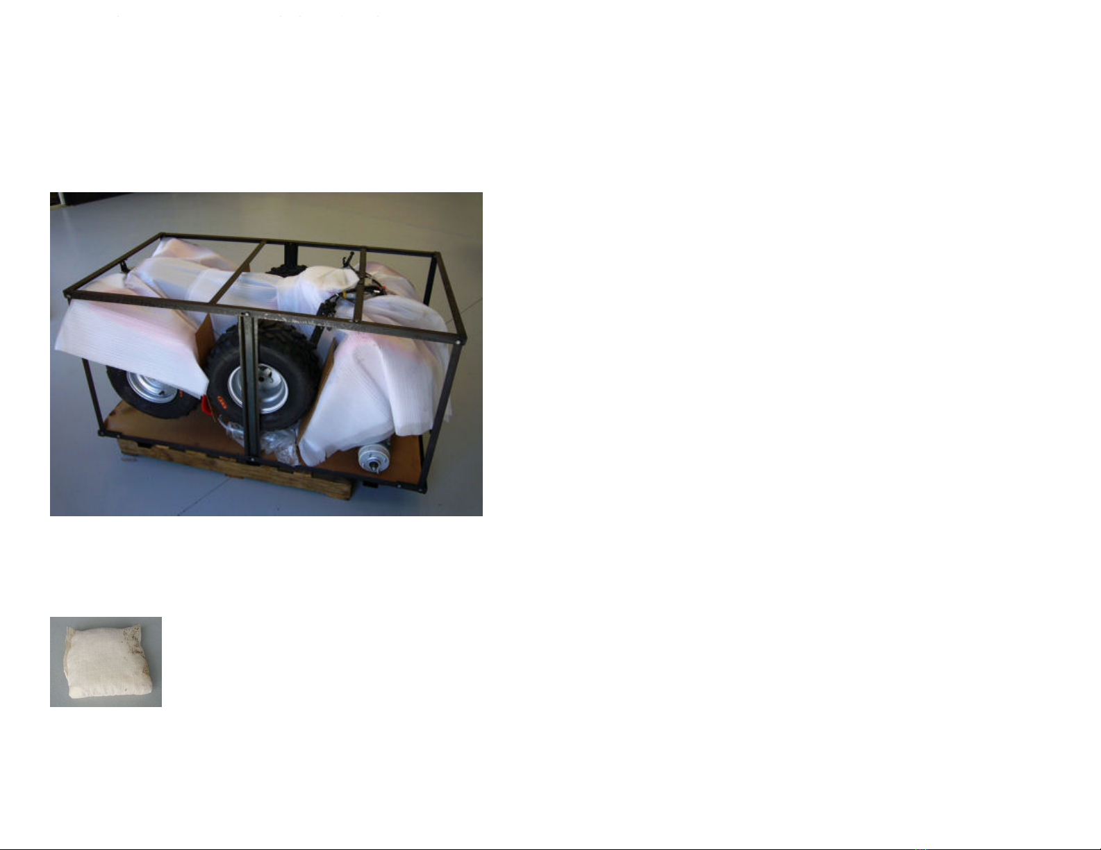
Unpack
.
Remove shrink wrap
,
packing straps
,
and card board
box cover. Remove all bolts attaching metal rame work to steel base.
Untie wires holding tire and wheel assembly to metal rame. See that
bolts are removed that attach handle bar mounting plate and bumpers
to metal rame, i applicable, be ore attempting to li t metal rame
work o o base. Care ully li t metal rame work straight up to remove,
taking care not to scu enders or bumpers while removing. This should
not be attempted by one person alone. Two people, li ting together,
can remove the rame work without causing damage to the ATV or harm
to themselves. Remove small box rom shipping rame base containing
all hardware, nuts, bolts, tool kit, battery and acid.
s ep01-fig1-Packing frame
2. Each ATV is shipped with a desiccant bag that is designed to
absorb moisture during shipping. It is o no urther value once the
shipping container is opened and should be discarded immediately to
avoid being played with by children or pets.
s ep02-fig1-Desiccan bag

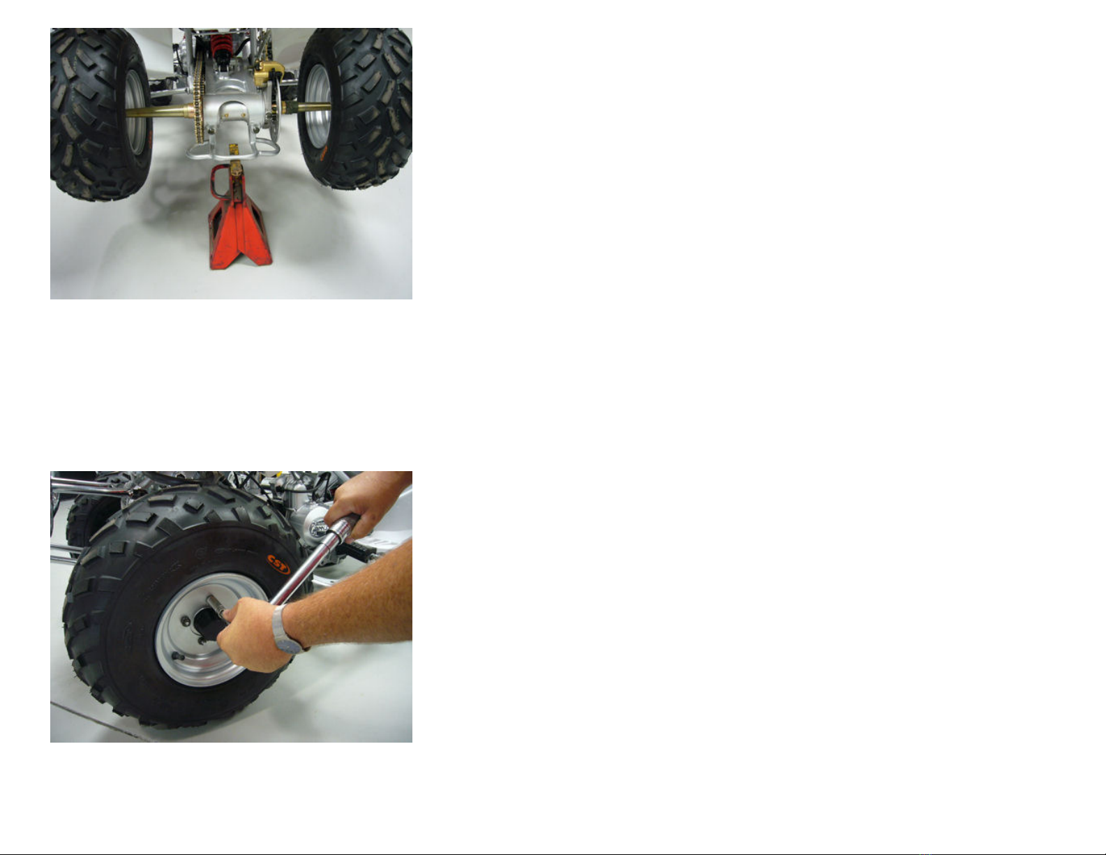
3
.
Li t and support the ront end o the ATV with a suitable jack
and jack stand that allows the vehicle to remain stable while attaching
the ront wheels, upper shock mounts, and bumper, i applicable.
s ep03-fig1-Fron jacks and suppor
4. WARNING! You must use an air gauge that has increments
smaller than 1 PSI to complete this step. Improperly in lated tires can
cause loss o control. Use the valve core tool supplied with the ATV tool
kit to tighten the valve core in each valve stem be ore attempting to
add air. In late the tires to seat the bead, taking care not to exceed the
tire manu actures recommendation (printed on the tire sidewall) or
maximum pressure to seat the bead. Release air until the correct
pressure is noted on the air gauge, according to the tire pressure
in ormation label on the ront ender o the ATV. Check each valve core
or leaks and install valve stem cap.
s ep04-fig1-Air gage wi h .5 pound incremen s
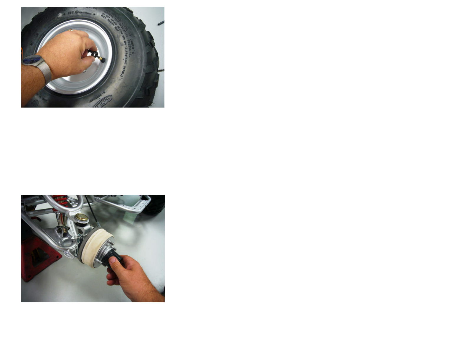
s ep04-fig2-Valve core ool.
5. Install the wheel center caps onto the ront hub washer
snapping irmly into place. Install the two ront wheels using the lug
nuts supplied. Never use any other type lug nut to attach wheels than
what was designed or the speci ic type wheel and ATV. Evenly snug
each lug nut by hand in a star pattern. Final wheel torque must be done
when ATV is sitting on lat ground. DO NOT attempt to per orm inal
wheel torque while ATV is supported on a jack stand. Install upper
shock mounting bolts and ront bumper with bolts provided, i
applicable to your model, taking care to properly snug all bolts
adequately and not over tighten.
s ep05-fig1-Ins all cen er cap

s ep05-fig2-Hand igh en lug nu s
6. Remove jack or support under ront end o ATV and let it rest
on the ront wheels. Go to the rear o packing rame and remove bolts
holding rear axle to rame base. Note: Packing methods may vary over
time on some models. Set parking brake or ront wheels to prevent
ATV rom rolling o packing rame base. Li t and support the rear o
ATV with a suitable jack and jack stand that allows the vehicle to
remain stable while installing the rear wheels.
s ep06-fig1-Parking brake
s ep06-fig2-Rear jack s and suppor
7. Follow the same procedures outlined in steps 3 and 4 or
in lating tires, installing center caps and mounting wheels on the rear
o ATV. When inished installing wheels care ully lower ATV, release
parking brake and roll o metal shipping rame onto lat, level sur ace.
Reset the parking brake and per orm the inal wheel torque procedure.
Torque all lug nuts to 26 Ft/Lbs. using a torque wrench with the
appropriate increments. Proceed in a star or criss cross pattern to
assure uni orm torque results.
s ep07-fig1-Final lug nu orque

8. Install handle bars with the bolts and hardware provided. See
that knurled areas on handle bars are evenly spaced between the two
halves o the pinch mount supports. Lightly snug attaching bolts and
position handle bars at the desired angle best suited or the com ort
and sa ety o the rider so that all hand controls are easily accessed and
operated. Turn wheels to ull le t and ull right positions to assure
adequate clearance or the rider’s legs and to check or binding cables
or wiring. Finish tightening handle bar mounting bolts evenly in a
criss-cross pattern and torque to 28 Ft/Lbs.
s ep08-fig1-Tigh en handle bar bol s

9
.
Plug the shi t indicator bulb and socket assemblies o main
harness into the rubber sockets on back o light console. Mount the
shi t indicator light console to the top o the handlebars. You will have
to veri y that they are plugged in correctly a ter battery is installed.
s ep09-fig1-Shif indica or bulbs in socke s
s ep09-fig2-Shif indica or console

10
.
All ATV’s are shipped with the uel lines unhooked
.
Connect the
uel supply line, coming rom the uel tank, to the uel inlet port on the
carburetor securing it with the spring clamp provided on the uel line.
Make sure the uel line is routed in a way to avoid kinks and to allow
or the proper gravity eed rom the tank. Do not run the uel line near
any part o the exhaust or hot section o the engine and take care to
tuck it in away rom the rider’s eet and legs so that it cannot be
snagged.
s ep10-fig1-Fuel line rou ing
11. Inspect the uel drain hose connected to the bottom o the
carburetor at the uel bowl to assure that it is ree o kinks and is
clamped or tie wrapped into place. This hose should always be heading
in a downward direction. See that the drain screw is seated in the
closed position be ore adding uel.
s ep11-fig1-Fuel drain hose rou ing
This manual suits for next models
1
Other CROSSRUNNER Offroad Vehicle manuals


