AD Boivin 2002 Snow Hawk User manual

2002-03
Set-up, service and repair
Manual
Snow Hawk™

HIGH ALTITUDE TECHNICAL DATA

1
700, rue Jean-Marchand
Lévis , QC Canada G6V 9G6
Tél.: (418) 838-3783 Fax.: (418) 838-3957
Web site: www.adboivin.com
2002 Snow Hawk Hi-Altitude Carburetor and Clutching Set-up:
GENERAL
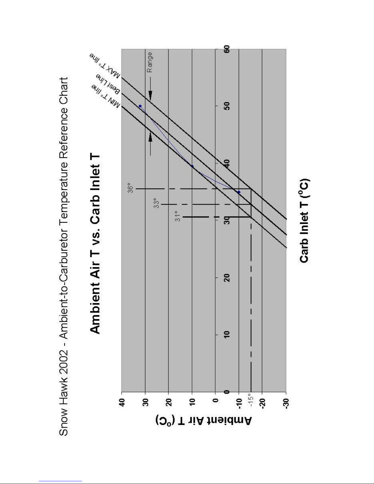
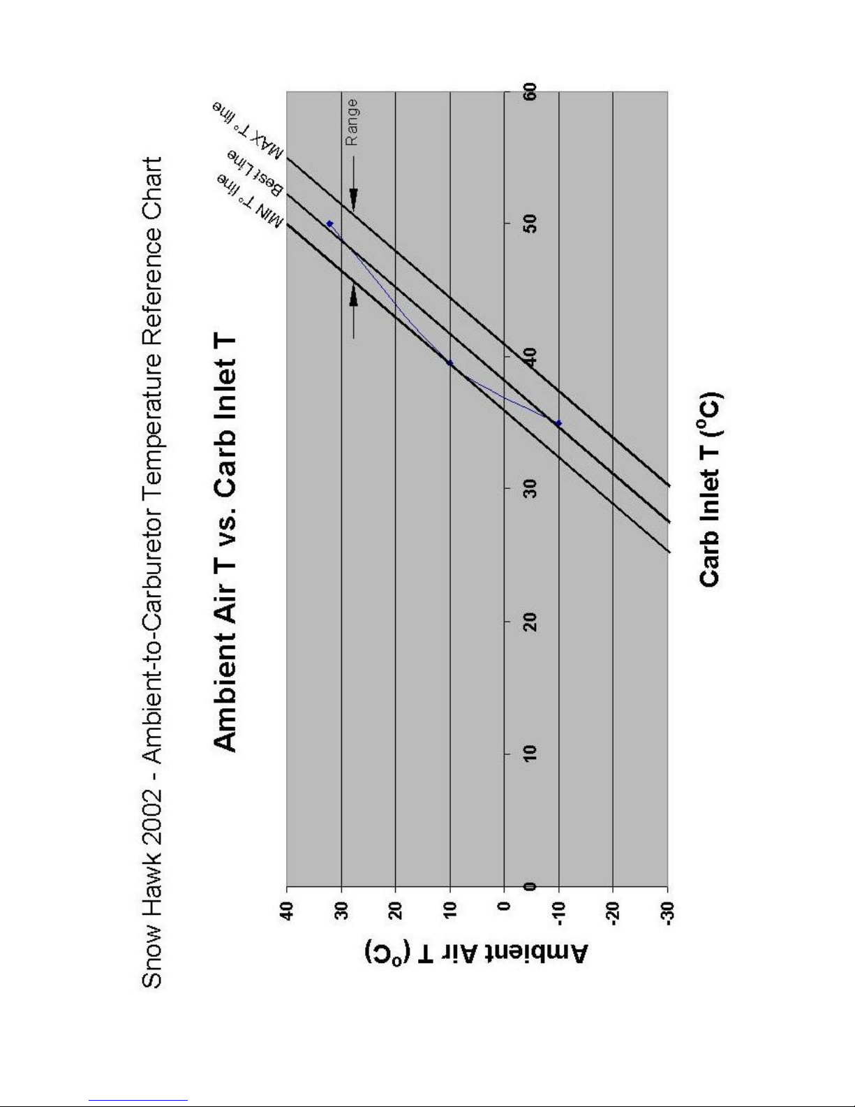
Since the 2002 Snow Hawk uses individual carburetor filters, carburetor inlet temperature is not
always the same as outside temperature, thus jetting is not. Influences from engine heat and
the exhaust system have a tendency to increase the engine bay temperature relative to outside
air temperature. We have plotted their approximate relationship in the graph shown on the
fourth page of this guide.
PROCEDURE -JETTING
How to use the Jetting chart:
1.Measure the outside (ambient) air temperature
2.Determine the altitude at your location
3.Using the chart on page four of this guide, determine the range of temperatures at the
carb inlet by first drawing a horizontal line to the right, away from the vertical ambient air
temperature axis.
4.Second, draw a vertical line upwards from each of the intersection points where the
horizontal line crosses over the Best Line, the MIN Toline and the MAX To line.
5.The temperature values where each of these vertical lines intersect the horizontal carb
inlet temperature axis are the approximate min, median and max temperatures that are
normally found at the carb inlet during normal operation at the specified outside air
temperature.
6.Adjust jetting set-up according to the carb inlet temperature given by the intersection of
the Best Lineand the ambient air temperature line.
7.After a short trial run, observe the plug color and performance feel of the vehicle closely.
If the mixture is too rich, try jetting according to the MAX Toline; If the mixture is too
lean, try jetting according to the MIN Toline.
8.The correct set-up will normally lie in this range.
9. An example is shown on page three of this guide where the outside air temperature
(ambient) is shown as –15oC. The resulting approximated carb inlet temperature ranges
from 31oC(minimum carb inlet temperature) to 36oC(maximum carb inlet temperature)
with the best approximation of the carb inlet temperature at 33oC.
NOTE: This set-up is a recommendation only. It is the responsibility of the owner to pay close
attention to spark plug color and engine performance when modifying the stock set-up to avoid
lean burn-down.

2
PROCEDURE –CLUTCHING
As a rule of thumb, it is recommended to remove one weight from each arm of the primary clutch
for each 2000ft increase in elevation. As a reference, the sea level (0 ft elevation) set-up has
nine weights at each of the three primary clutch arms.
3
4

5
MAIN JET CHART
@CARB
°C 01000 2000 3000 4000 5000 6000 7000 8000 9000 10000 Feet
°F
0
305
610
914
1219
1524
1829
2134
2438
2743
3048
Meter
20 230 220 220 210 200 190 180 180 170 160 160 PTO
68
220
210
200
190
190
180
170
160
160
150
150
MAG
25 230 220 210 200 190 190 180 170 170 160 150 PTO
77
210
210
200
190
180
170
170
160
150
150
140
MAG
30 220 220 210 200 190 180 180 170 160 150 150 PTO
86
205
200
200
190
180
170
170
160
150
150
140
MAG
35 220 210 200 190 190 180 170 160 160 150 140 PTO
95
210 200 190 190 180 170 160 160 150 140 140
MAG
40 210 210 200 190 180 170 170 160 150 150 140 PTO
104
200 200 190 180 170 170 160 150 150 140 130
MAG
45 210 200 190 180 180 170 160 150 150 140 140 PTO
113
200
190
180
180
170
160
150
150
140
140
130
MAG
50 200 190 190 180 170 160 160 150 140 140 130 PTO
122
190
190
180
170
160
160
150
140
140
130
130
MAG
NOTE: These values are suggestions only, tuners are reminded to pay very close attention to plug color and performance
feel in order to avoid lean burndown.
PILOT JET CHART
@CARB
°C 01000 2000 3000 4000 5000 6000 7000 8000 9000 10000 Feet
°F
0
305
610
914
1219
1524
1829
2134
2438
2743
3048
Meter
20 65 60 60 55 55 55 50 50 45 45 45 PTO
68
65
60
60
55
55
55
50
50
45
45
45
MAG
25 65 60 60 55 55 50 50 50 45 45 40 PTO
77
65
60
60
55
55
50
50
50
45
45
40
MAG
30 60 60 55 55 55 50 50 45 45 45 40 PTO
86
60
60
55
55
55
50
50
45
45
45
40
MAG
35 60 60 55 55 50 50 45 45 45 40 40 PTO
95
60
60
55
55
50
50
45
45
45
40
40
MAG
40 60 55 55 50 50 50 45 45 40 40 40 PTO
104
60
55
55
50
50
50
45
45
40
40
40
MAG
45 60 55 55 50 50 45 45 45 40 40 40 PTO
113
60
55
55
50
50
45
45
45
40
40
40
MAG
50 55 55 50 50 45 45 45 40 40 40 35 PTO
122
55
55
50
50
45
45
45
40
40
40
35
MAG
NOTE: * When the difference between suggested pilot jet size is less than 15, the correction can be made through airscrew adjustment.
*Shaded areas indicate stock set-up
TUNING: *The "zero setting" for a pilot jet is with the airscrew set to 1.5 turns out from full tight (I.e. zero position).
*To effectively reduce the size of a pilot jet, turn the airscrew further out; 1/4 turn outwards [CCW] is equal to reducing a pilot
jet one size, or equivalently reducing the jet number by 5.
*Airscrew range of adjustment varies from 1 to 3 turns outwards. 1 to 2 turns outwards is optimal.

SPECIFICATIONS 18 - 1
ENGINE
SNOW HAWK SPECIFICATIONS
Engine type
SUSPENSION
IBC Formula, cam on countershafti
7100 RPM
3450 RPM
304.8 (mm) / 11.9 (in)
28
56
No. of cylinders
Displacement
Bore
Stroke
Carburation
Exhaust Sytem
DRIVE SYSTEM
Primary clutch
Secondary clutch
Max RPM
Engagement
Clutch C-C distance
Upper sprocket - # teeth
Lower sprocket - # teeth
Drive sprocket diameter
Brake system
Secondary transmission
61 (mm) / 2.4 (in)
2 x Mikuni VM 34 ( choke )
Tuned pipe and silencer
IBC Power Bloc
Rotax 503, fan cooled, piston port
2
496.7 (cc) / 30.3 (in3)
72 (mm) / 2.8 (in)
High efficiency cog belt (8mm)
177 (mm) / 6.9 (in)
Brembo; floating 34 mm twin piston on 175 mm disc
308 (mm) / 12 (in)
385 (mm) / 15 (in)
PAIOLI 46mm inverted fork - adj. rebound and compression damping
A.D. Boivin EXPERT " X " c/w rebuildable Kayaba HPG shocks
Front suspension
Vertical Travel
Rear Suspension
Vertical Travel
SPECIFICATIONS
18

SPÉCIFICATIONS 18 - 2
UHMW polyethylene
Color Blue / Orange
Bellypan
Ski
87
Bombardier pre-mix oil
240W @ 6000 RPM
HMW Polyethylene
308 (mm) / 12 (in)
350 (lbs) / 160 (kg)
920 (mm) / 35.8 (in)
Pre-mix 40 : 1
860 (mm) / 33.5 (in)
283 (mm) / 11 (in)
257 (mm) / 10 (in)
Official dry weight
Ski length
Ski width
835 (mm) / 32.5 (in)
1233 (mm) / 48 (in)
2698 (mm) / 105 (in)
DIMENSIONS
Overall length
Headlight high/low beam
MATERIALS
Chassis
Hood
2 x 30 / 30 W
6061-T6 Aluminium
HMW Polyethylene
Recommended fuel
Recommended octane level
Recommended oil
Electrical output ( AC )
Nominal track length
Lug height
CAPACITIES
Fuel capacity
58 (mm) / 2.25 (in)
17.5 (liters) / 4.5 (US gal)
3074 (mm) *3495* (mm) / 121 (in) *136* (in)
Nominal track width
Seat height
Overall width
Overall height
Ground clearance
WIRE, CABLE AND HOSE ROUTING 17-1
1
1
2
3
4
1
2
3
WIRE, CABLE AND HOSE ROUTING
uu WARNING
Make sure that all the wires are well set in the terminals
and that the connector holders are well installed. Keep
the wires away from any rotating, moving, heating or
vibrating part. If necessary, use good retaining devices.
When reassembling, it is important to always re-install the wires
to the stock positions.
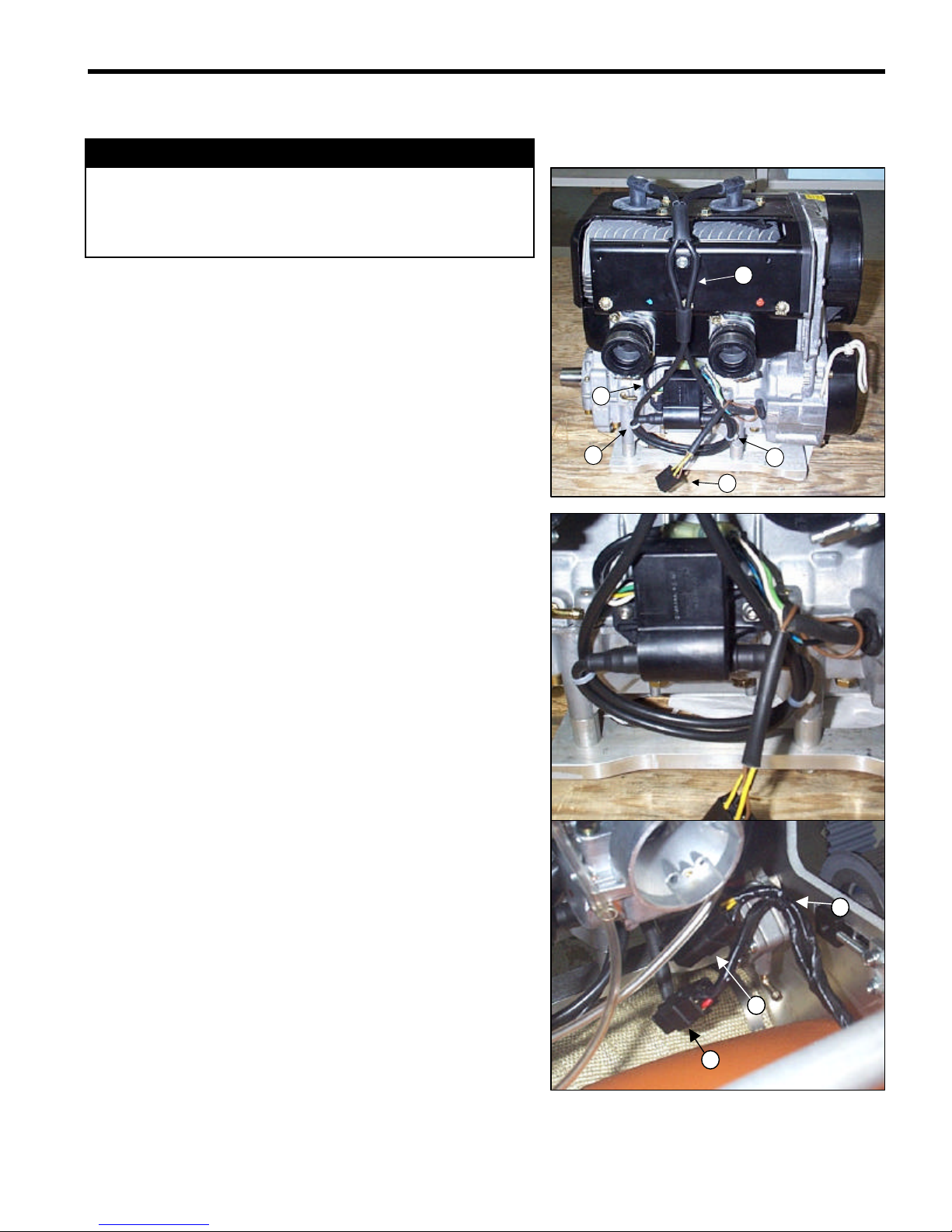
SPARK PLUG WIRES AND ELECTRONIC BOX
1-Nylon fasteners
2-Electronic box wires
3-Spark plug wires
4-Engine electrical power output
When replacing the electronic box or the spark plug wires, it is
important that the wires be put back in the stock arrangement.
The connecting wire for the electronic box (No. 2) and the two
spark plug wires (No. 3) must be installed in the way shown in
the photograph.
Use two tie wraps (No. 1) to keep the spark plug wires in place.
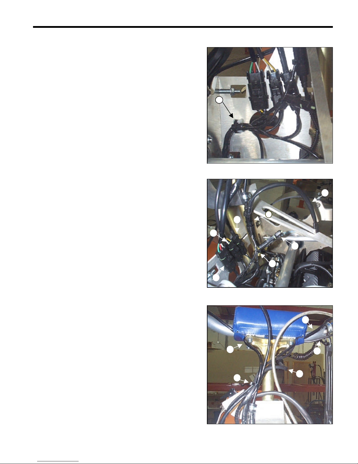
ROUTING THE WIRES
1-Connection to the voltage regulator
2-Connection to the engine power source
3-Tie wrap
Using a tie wrap, attach the two bundles of wires together to the
empty hole in the fuel pump.
WIRE, CABLE AND HOSE ROUTING 17-2
2
1
2
8
3
8
4
8
1
8
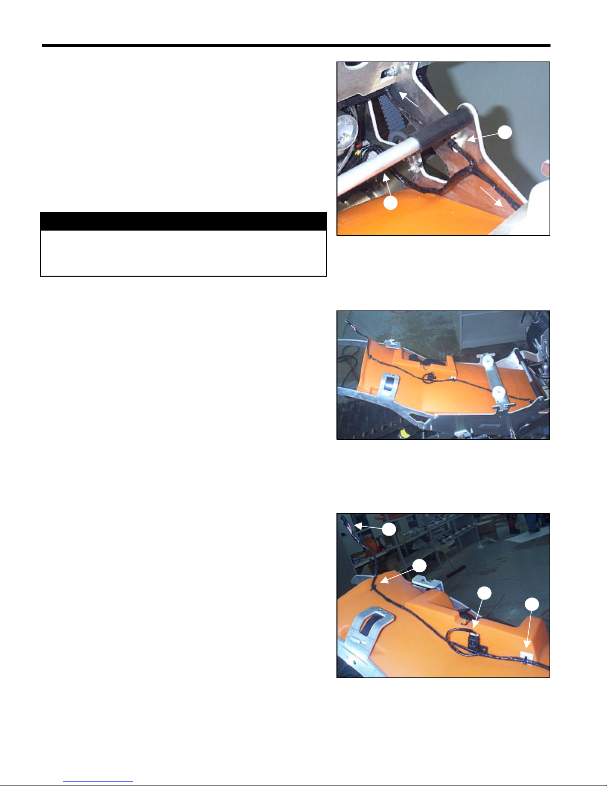
Under the transversal shaft (No. 1) of the chassis, the wiring
separates into two segments, one going toward the front of the
vehicle and the other going toward the back
Using a tie wrap, secure the wiring that goes toward the front of
the vehicle in the cable attachment (No. 2).
2-Nylon cable attachment
uu WARNING
It is important that the wires be installed exactly where
they are intended to avoid interference during operation.
(Refer to the photograph on the right)
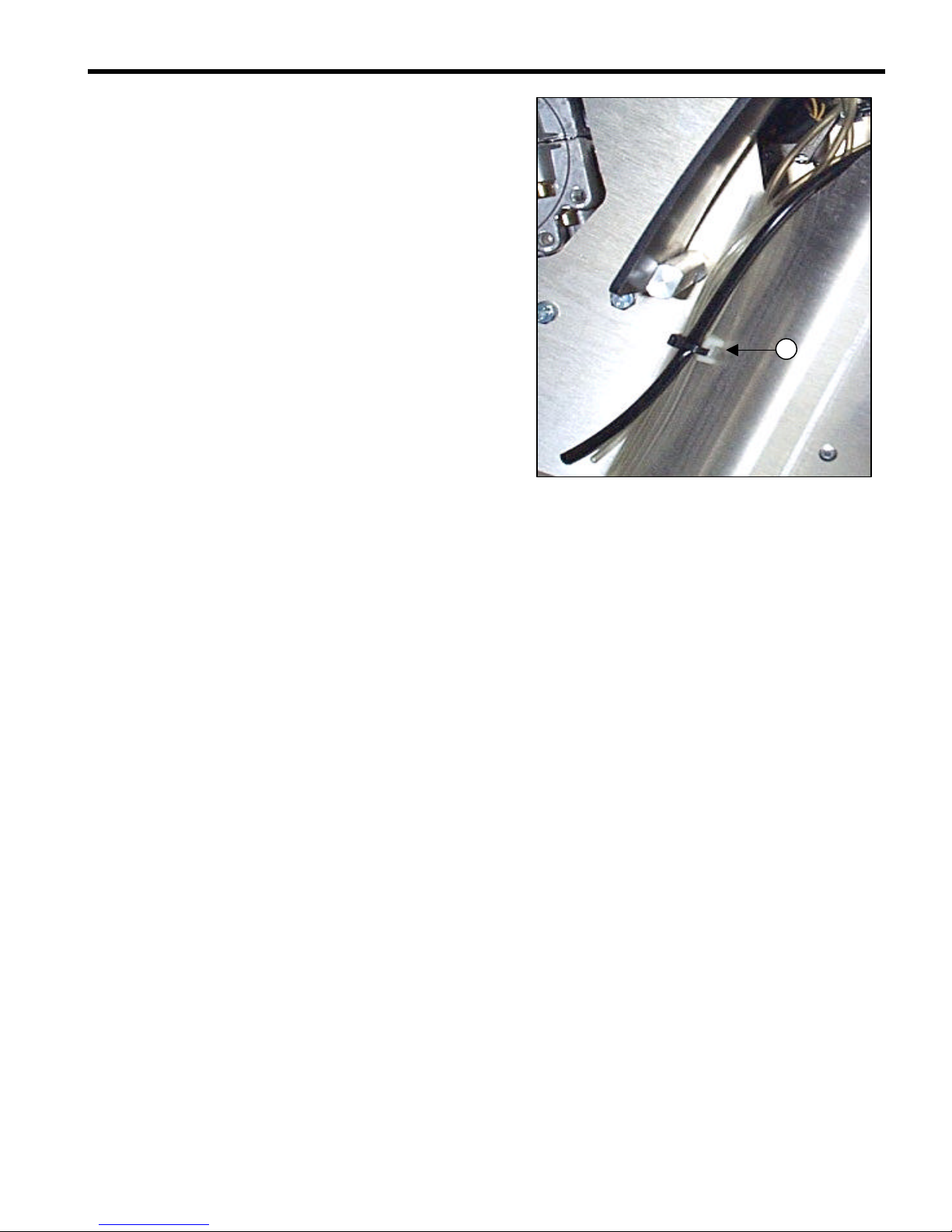
The section of the wiring harness going toward the rear of the
vehicle must pass under the gas tank bracket.
1-Tie wrap
2-Adhesive nylon cable fastener
3-Safety fuse
4-Tail light connection
Using a tie wrap, secure the wiring in the adhesive nylon
fastener (No.2).
Position the fuse (No. 3) correctly in the connector holder.
Using a tie wrap, secure the wiring harness to the two holes.
(Refer to the photograph on the right -No. 1).
WIRE, CABLE AND HOSE ROUTING 17-3
1
B
A
E
C
D
1
2
c
1
C
D
E
The forward wiring section comes up inside the steering column
plate of the vehicle and is anchored with a tie wrap in the nylon
cable fastener (No. 1).
1. Nylon cable fastener
After the nylon cable fastener, the wiring divides into five
segments (A-E).
Secure the accessories wire to the wire for the headlight, using
a tie wrap (No. 1).
Join the wire for the headlight to the accelerator cable, using a
nylon fastener (No. 2).
A-Headlight wire
B-Accessories wire
C-Engine cutoff and emergency stop
D-Stop lamp microswitch
E-Dimmer switch
Bring together the wires of the switch for the lights (E), of the
switch for the stop light (D) of the engine cutoff and emergency
stop (C) and the accelerator cable, and join them using a nylon
fastener (No. 1).
The wires for the engine cutoff and the emergency stop
separate into two segments after the junction of wires in No. 1.
C-Emergency stop
c-Engine cutoff
Place the wires for the emergency stop, the switch for the stop
light, and the switch for the lights under the protective cushion
(see the photograph).
The cab
Nylon fasteners anchor the cab wiring in three places:

WIRE, CABLE AND HOSE ROUTING 17-4
3
1
2
1
2
1
1
1. On the retaining screw of the light (No. 1)
2. On the protective screen (grille) (No. 2)
3. On a nylon cable attachment secured to the back
protective screen (grille) of the cabin (No. 3).
CABLE ROUTING
Throttle cable
oThe throttle cable is secured in the accelerator (No. 1).
oPass the cable in front of the handlebars.
oUsing a cable collar, attach the accelerator cable to the
retaining screw of the steering column (No. 2).
uu WARNING
Before installing them, make sure the cables are in good
condition. Install the ends of the cables carefully and
secure them solidly in place. Make sure they are routed
where they should be and keep them away from any
rotating, moving, heating or vibrating part.
The accelerator cable divides into two cables, one for each
carburetor (No. 1).
(See section 3, Fuel System, for instructions on installing the
throttle cable on the carburetors.)
Choke cables
oInstall the choke cables in the part that holds the cables
up (No. 1).

WIRE, CABLE AND HOSE ROUTING 17-5
1
1
2
3
oRun the cables along the gas tank and pass them
through the hole in the plate of the steering column (see
the arrow on the photograph).
oPass the choke cables under the electric wires and over
the carburetor cables.
oThen install the choke cables on the carburetors.
lNOTICE:
One of the two choke cables is longer than the other. Install it
on the carburetor that is farther away.
Recoil starter cord
oPass the recoil starter cord over the pulley (No. 1).
oThen pass it under the pulley (No. 2).
oThen pass the cord through the guide ring (No. 3).
oInstall the starter handle.

WIRE, CABLE AND HOSE ROUTING 17-6
1
1
HOSE ROUTING
uu WARNING
Always make sure that the conduits are well secured to
the connectors, that they are neither perforated nor
mixed-up, and that they are well positioned, far from any
rotating, moving, heating or vibrating parts. In addition,
check to make sure there are no leaks. Replace them if
necessary.
Brake hose
oThe brake hose is secured to the brake master cylinder.
oPass the hose in front of the handlebars and steering
column.
oThe hose then goes down behind the steering column
plate.
oThe brake hose is attached along the plate of the
steering column with two tie wraps (No. 1).
oThe hose then goes outside the chassis through the
hole on the left side, near the brake system.
oThe hose is then secured to the calliper.

WIRE, CABLE AND HOSE ROUTING 17-7
4
2
3
1
3
2
5
Vacuum
Fuel feeder lines:
The fuel pump (No. 1) has two intakes and two outlets.
The two intakes are:
1. The gas tank feed (No. 4)
2. The vacuum (No. 2)
The two outlets are:
1. The carburetor feed on the MAG side (No. 3).
2. The carburetor feed on the PTO side (No. 5).
After leaving the pump, the vacuum hose goes along the base of
the engine under the two carburetor intake adapters.
The hose is installed onto in the vacuum fitting at the base of the
engine.
Make sure the spring clamp is well installed to ensure an airtight
seal.

WIRE, CABLE AND HOSE ROUTING 17-8
3
5
2
1
1
1
1
Hose (No. 3) passes under the choke cable and the throttle
cable, and connects to the MAG side carburetor.
Hose (No. 5) passes along the base of the engine housing and
over the two carburetor intake adapters. It goes around the
throttle cable and the choke cable, and connects to the PTO
side carburetor.
Carefully install all the spring clamps.
Overflow hose and carburetor vent hoses
The overflow hose is connected to the cap of the gas tank. It is
then routed down through the steering column tube.
The overflow hose (No. 2) comes out at the end of the steering
column and passes between the two carburetors.
The carburetor vent hoses (No. 1) and the overflow hose (No. 2)
are grouped together and pass outside the chassis through a
hole near the brake system.
WIRE, CABLE AND HOSE ROUTING 17-9
3
The hoses go along the chassis and are attached to the nylon
cable fastener by a tie wrap.

SPECIAL TOOLS 16 -1
P/N Item Description
X-1756 Primary Clutch Puller
529 027 300 Spring Compressor
43990092 Belt Tensioning Tool
529 027 600 Primary Clutch Tool
529 031 103 Application Plate
529 031 102 Extractor
529 031 200 Secondary slider installation tool
529 031 300 Secondary slider installation tool
529 008 700 Secondary belt changing tool
404 112 000 Mikuni VM Toolkit
529 009 900 Hose Pinch Clamp
420 876 357 Cooling Fan Nut Removal Tool
529 021 000 Piston Wrist Pin Extractor
529 023 400 Rubber Cushion
529 016 900 Piston Circlip Installation Tool
420 876 970 Piston Ring Compressor
413 701 000 Anti-Seize Compound
420 876 620 Thickness Gauge
420 876 824 Positioning Gauge
413 708 100 Curing Spray
449.450.020 A.D Boivin Complete Fork Servicing Toolkit
949.000.046 Fork Top Cap Tool
949.000.045 Fork Cartridge Removal Tool
949.000.016 Fork Seal Drivers
08-0B75 Needle Adapter
413 709 400 Kayaba Shock Oil
420 876 080 Stator plate puller
529 022 500 Magneto puller
419 003 300 Ignition timing tester
SPECIAL TOOLS
16
DIMENSIONS AND TOLERANCES 15 -1
ENGINE
Engine type Rotax 503
Bore mm 72.00
(in) (2.835)
Stroke mm 61.00
(in) (2.402)
Displacement cm
3
496.70
(in
3
)
(30.31)
Compression Ratio 6.20
Max RPM Range 7000-7200
Piston ring type (1
st
, 2
nd
)
ST/R
Piston ring opening (new) mm 0.2
(in) (0.008)
(wear limit) mm 1.00
(in) (0.039)
Piston ring/groove play (new) mm 0.04
(in) (0.0016)
(wear limit) mm 0.2
(in) (0.008)
Piston/Cylinder play (new) mm 0.08
(in) (0.031)
(wear limit) mm 0.2
(in) (0.008)
Maximum connecting rod axial play (new) mm 0.2
(in) (0.008)
(wear limit) mm 1.00
(in) (0.039)
Maximum crankshaft axial play mm 0.3
(in) (0.018)
Maximum crankshaft curvature mm 0.08
(in) (0.031)
ELECTRICAL
Magneto output W240
Ignition type CDI
Spark plug type NGK BR9ES
Spark plug gap mm 0.45
(in) (0.018)
Ignition timing before TDC mm 1.66
(in) (0.065)
Primary lgnition coil
W
230 - 330
Lighting coil
W
0.23 - 0.28
Secondary Ignition coil
W
5.1 - 6.3
Head lamp bulb W30/30
Tail lamp bulb W18/23
Fuse A25
DIMENSIONS AND TOLERANCES
15
Table of contents
Other AD Boivin Offroad Vehicle manuals


