Panasonic KX-TD500 Operating instructions

Please read this manual before connecting the Digital Super Hybrid System and save this manual
for future reference.
Thank you for purchasing the Panasonic Model KX-TD500, Digital Super Hybrid System.
Model No.
KX-TD500
Digital Super Hybrid System
Programming Guide
DIGITALSUPERHYBRIDSYSTEMRUNOFFLINEALARM

Introduction
2 Programming Guide
Introduction
This Programming Guide is designed to serve as a technical reference for the Panasonic Digital
Super Hybrid System, KX-TD500.It provides step-by-step instructions forperforming system
programming using the Maintenance Console software for a PC.
About the Other Manuals
Along with this Programming Guide, the following manuals are available:
Features Guide
Describes every basic, optional and programmable features of the KX-TD500 System in
alphabetical order.
User Manual
Provides operating instructions for the end users using Proprietary Telephones (PTs),
Single Line Telephones (SLTs) or DSS consoles.
Installation Manual
Describes information necessary for installing the hardware and system maintenance.
Note
• Throughout this manual the term "he" or "she," "his" or "her" may be used. In order to
improve readability rather than continually use he/she we have only used one of these
terms. The term "he" or "she" should be taken as being interchangeable.
Notice
• This manual does not show the complete model number that indicates the country/area
where your models should be used. The model number of your unit is found on the label
affixed to the unit.
Trademarks
• Microsoft and Windows are either registered trademarks or trademarks of Microsoft
Corporation in the United States and/or other countries.
• All other trademarks identified herein are the property of their respective owners.
MODEL NO.
(label)

Table of Contents
Programming Guide 3
Table of Contents
1 Configuration.................................................................................... 5
1.1 Configuration..................................................................................................................6
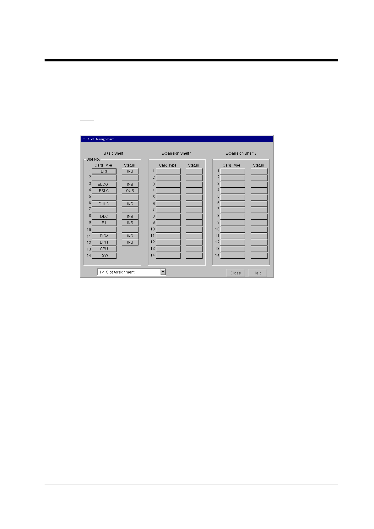
1.2 Slot Assignment ..............................................................................................................7
1.3 Trunk Port Assignment ...............................................................................................11
1.4 Extension Port Assignment..........................................................................................13
1.5 VPS (DPT) Port Assignment .......................................................................................19
1.6 T1 Port Assignment......................................................................................................25
1.7 E1 Port Assignment......................................................................................................28
1.8 DISA Port Assignment.................................................................................................31
1.9 BRI Port Assignment ...................................................................................................32
1.10 PRI Port Assignment..................................................................................................35
2 System.............................................................................................. 39
2.1 System............................................................................................................................40
2.2 Tenant............................................................................................................................41
2.3 Numbering Plan............................................................................................................48
2.4 Class of Service (COS).................................................................................................68
2.5 System Timer................................................................................................................79
2.6 Local Hunt Sequence....................................................................................................90
2.7 Trunk to Trunk Restriction.........................................................................................91
2.8 System Option...............................................................................................................92
2.9 Language Data............................................................................................................119
3 Group............................................................................................. 121
3.1 Group...........................................................................................................................122
3.2 Trunk Group...............................................................................................................123
3.3 Extension Group.........................................................................................................136
3.4 Paging Group..............................................................................................................149
3.5 Incoming Group .........................................................................................................150
3.6 OGM Group................................................................................................................163
4 Line ................................................................................................ 167
4.1 Line..............................................................................................................................168
4.2 Trunk Line..................................................................................................................169
4.3 Extension Line ............................................................................................................184
4.4 DSS Console................................................................................................................206
4.5 Doorphone...................................................................................................................214
4.6 External Paging ..........................................................................................................216
4.7 ISDN Extension Line..................................................................................................219
4.8 PC Console Line .........................................................................................................225
5 Features......................................................................................... 241
5.1 Features.......................................................................................................................242
5.2 System Speed Dialling................................................................................................243
5.3 Phantom Extension.....................................................................................................246
5.4 Emergency Dial Code.................................................................................................248

Table of Contents
4 Programming Guide
5.5 Quick Dialling............................................................................................................ 249
5.6 Account Code............................................................................................................. 250
5.7 Special Carrier Code................................................................................................. 252
5.8 Waiting Second Dial Tone Code............................................................................... 253
5.9 Absent Message.......................................................................................................... 255
5.10 DISA/TIE User Code............................................................................................... 257
5.11 VPS Integration ....................................................................................................... 259
5.12 Caller ID Modification............................................................................................ 268
5.13 Caller ID Registration............................................................................................. 271
5.14 UCD Time Table...................................................................................................... 274
5.15 Charge....................................................................................................................... 276
5.16 Hotel.......................................................................................................................... 279
5.17 T7710 One-Touch Dialling...................................................................................... 284
6 Toll Restriction ............................................................................. 285
6.1 Toll Restriction .......................................................................................................... 286
6.2 TRS Deny Code.......................................................................................................... 287
6.3 TRS Exception Code ................................................................................................. 289
7 ARS (Automatic Route Selection)............................................... 291
7.1 ARS (Automatic Route Selection)............................................................................ 292
7.2 Time Table.................................................................................................................. 293
7.3 Leading Digits Table ................................................................................................. 294
7.4 Routing Plan............................................................................................................... 296
7.5 Digits Modification Table ......................................................................................... 298
8 Private Network............................................................................ 301
8.1 Private Network......................................................................................................... 302
8.2 TIE Routing Table..................................................................................................... 303
9 DDI/DID ........................................................................................ 305
9.1 DDI/DID ..................................................................................................................... 306
9.2 Number Transformation........................................................................................... 307
10 Maintenance................................................................................ 313
10.1 Maintenance............................................................................................................. 314
10.2 External Modem 1/2................................................................................................ 315
10.3 External Modem 2/2................................................................................................ 317
10.4 SMDR ....................................................................................................................... 318
10.5 Power Failure Transfer........................................................................................... 325
10.6 System Parameters.................................................................................................. 327
10.7 System Time............................................................................................................. 335
11 Programming Error Messages.................................................. 339
11.1 Error Messages (EXXXX) ...................................................................................... 340
11.2 Warning Messages (WXXXX)................................................................................ 351
11.3 Information Message (IXXXX).............................................................................. 355
12 Default Values............................................................................. 357

Configuration
Programming Guide 5
Section 1
Configuration

Configuration
6 Programming Guide
1.1 Configuration
Used to determine the basic system configuration.

Configuration
Programming Guide 7
1.2 Slot Assignment
Assigns the type of service cards, inserted in the free slots in the basic and expansion shelves.
Note
•The DPH/DPHG card is not available in some countries/areas.

Configuration
8 Programming Guide
Parameter Card Type
Default Blank
Value Range Please refer to "Description/Function."
Description/Function Specifies the type of service cards inserted in the free slots in the
basic and expansion shelves.
<Selection>
None: Not assigned.
AGC: Automatic Gain Control card
BRI: ISDN Basic Rate Access Interface card
DHLC: Digital Hybrid Line Circuit card
DID: Direct Inward Dialling Trunk card
DID-2W: Both-way Direct Inward Dialling Trunk card
DID-MFC: Direct Inward Dialling Trunk with MFC card
DISA: Direct Inward System Access card
DLC: Digital Proprietary Line Circuit card
DPH: Doorphone Circuit card
DPHG: Doorphone Circuit card
E1: E1 Digital Trunk card
E&M: E&M card (TIE Line card)
ELCOT: Enhanced Loop Start Central Office Trunk card
ERMT: Enhanced Remote Circuit card
ESLC: Enlarged Single Line Telephone Circuit with Message
Waiting card
GCOT: Ground Start Central Office Trunk card
HLC: Hybrid Line Circuit card
LCOT: Loop Start Central Office Trunk card
OPX: Off Premise Extension card
PCOT: Loop Start Central Office Trunk with Pay Tone
Detection card
PLC: Proprietary Line Circuit card
PRI30: ISDN Primary Rate Access Interface card
PRI23: ISDN Primary Rate Access Interface card
RCOT: Loop Start Central Office Trunk with Polarity
Reversal Detection card
RMT: Remote Circuit card
SLC: Single Line Telephone Circuit card
SLC-M: Single Line Telephone Circuit with Message Waiting
card
T1: T1 Digital Trunk card

Configuration
Programming Guide 9
Parameter Card Type
Description/Function Notes
•To change the current Card Type to a new one, delete the
current setting first by selecting "None" and then assign a
new Card Type.
•CPU - Slot No.13 of the Basic Shelf is fixed to CPU (Central
Processing Unit) card.
•TSW- Slot No.14 of the Basic Shelf is fixed to TSW (T-
Switch) card.
•Card Properties
"Card Properties" screen lists and lets you customise the
operating characteristics associated with the following
optional cards.
Extension Cards: DHLC, DLC, ESLC, HLC, OPX, SLC,
SLC-M
Trunk Cards: BRI, DID, DID-2W, DID-MFC, E1, E&M,
ELCOT, GCOT, LCOT, PCOT, PRI30,
PRI23, RCOT, T1
Resource Cards: DISA, ERMT
•Editing Card Properties Parameters
You can edit Card Properties parameters according to your
needs. To go to "Card Properties" screen, click [Card Type]
button of the target card on this screen. Then click
.
•Help file
You can get detailed information on Card Properties
parameters by opening "Help" menu on the Menu bar.
•There are the following two types of PRI cards, PRI23 and
PRI30. Please choose either one appropriate to your ISDN
carrier. Specifications of PRI23 and PR130 cards are
described in Section "1.6 Specifications" in the Installation
Manual.
Reference •1.4 Service Cards Description (I/M)

Configuration
10 Programming Guide
Parameter Status
Default —
Value Range 1. INS
2. OUS
3. FAULT
Description/Function Used to set the status of the service cards.
1. INS (In-Service):
The target service card is operating normally.
2. OUS (Out-of-Service):
Programming data for the target service card is entered, but the
target service card is not assigned to the system.
3. FAULT:
The target service card is defective (hardware). In this case, the
LED indicator on the service card is lit.
Reference None

Configuration
Programming Guide 11
1.3 Trunk Port Assignment
Used to assign each trunk port in the system to one of up to 48 trunk groups.
Parameter Card No.
Default —
Value Range XXX : YYY [XXX : Card No. (101-314), YYY : Card Type]
Description/Function Specifies the physical number of the trunk card and its type, which
you are going to programme.
Reference •1.2 Slot Assignment (P/G)
Parameter Group No.
Default DID/DID-2W/DID-MFC card: 47, E&M card: 48, Others : 1
Value Range 1 - 48
Description/Function Specifies the trunk group (1-48) to which the trunk port is assigned.
Note
•Each trunk port must be assigned to a Trunk Group.
This programme defines the Trunk Group assignment for
each trunk port.
Reference •1.3 System Features (F/G)
–Trunk Group
•3.2 Trunk Group (P/G)

Configuration
12 Programming Guide
Parameter Status
Default —
Value Range 1. INS
2. OUS
3. FAULT
Description/Function Specifies the operating status of the trunk port.
1. INS: The trunk port is In-Service.
2. OUS: The trunk port is Out-of-Service.
3. FAULT: The trunk port is defective.
Reference None

Configuration
Programming Guide 13
1.4 Extension Port Assignment
Used to set various parameters for extension ports.
XDP extensions are on ports 9 through 16 of a DHLC card.
Parameter Card No.
Default —
Value Range XXX : YYY [XXX : Card No. (101-314), YYY : Card Type]
Description/Function Specifies the physical number of the extension card and its type,
which you are going to programme.
Reference •1.2 Slot Assignment (P/G)

Configuration
14 Programming Guide
Parameter Attribute
Default TEL
Value Range 1. TEL
2. DSS
3. VPS (DPT)
4. PC Console
Description/Function Specifies the attribute of the terminal which is to be connected to
the extension port.
1. TEL:
Select this option when you connect a telephone set to the
extension port.
2. DSS:
Select this option when you connect a DSS console to the
extension port.
3. VPS (DPT):
Select this option when a port of Panasonic Voice Processing
System (one that supports DPT Integration) is connected to the
extension port.
4. PC Console:
Select this option when you connect a PC Console to the
extension port.
A PC Console can be connected to a DHLC card (port 1 only)
or a DLC card (port 1 and 9 only).
Notes
•"DPT integration (except TVP300)" does not function
unless the VPS is connected to a DLC or DHLC card
whose LPR Version (ROM Version) is 1 or later.
•A PC Console and "DPT integration (TVP300 only)" do
not function unless it is connected to a DLC or DHLC
card whose LPR Version (ROM Version) is 2 or later.
•You can confirm the LPR Version (ROM Version) of the
DLC and the DHLC card in "Card Properties" screen for
each card. For information on "Card Properties" screen,
please refer to "Card Type" in Section "1.2 Slot
Assignment."
•There is a limit of 8 VPS (DPT) ports per card.
•There is a limit of 16 VPS (DPT) ports per shelf.
Reference •1.5 VPS (DPT) Port Assignment (P/G)
•4.3 Extension Line (P/G)
•4.4 DSS Console (P/G)
•4.8 PC Console Line (P/G)

Configuration
Programming Guide 15
Parameter Tel. Type
Default (Display only)
Value Range Please refer to "Description / Function."
Description/Function Displays the model number of telephone set which is currently
connected to the extension port.
<Telephone type list>
Unknown: Not connected or Single Line Telephone
TD50300: PC Console
T7130: APT with SP-PHONE, 1-Line Display (12-CO)
T7020 / T7320: APT with SP-PHONE (12-CO)
T7033: APT with SP-PHONE (12-CO)
T7030 / T7330: APT with SP-PHONE, 1-Line Display (12-CO)
T7050 / T7350: APT with MONITOR (12-CO)
T7055: APT with MONITOR (3-CO)
T7220: DPT with SP-PHONE (24-CO)
T7230: DPT with SP-PHONE, 2-Line Display (24-CO)
T7235: DPT with SP-PHONE, 6-Line Display (12-CO)
T7250: DPT with MONITOR (6-CO)
T7420: DPT with SP-PHONE (12-CO)
T7425: DPT with SP-PHONE (24-CO)
T7431: DPT with SP-PHONE, 1-Line Display (12-CO)
T7433: DPT with SP-PHONE, 3-Line Display (24-CO)
T7436: DPT with SP-PHONE, 6-Line Display (24-CO)
T7450: DPT with MONITOR (12-CO)
T7451: DPT with MONITOR (4-CO)
T7520: DPT with SP-PHONE (12-CO)
T7531: DPT with SP-PHONE, 1-Line Display (12-CO)
T7533: DPT with SP-PHONE, 3-Line Display (12-CO)
T7536: DPT with SP-PHONE, 6-Line Display (12-CO)
T7550: DPT with MONITOR (12-CO)
T7560: DPT with MONITOR (8-CO)
T7565: DPT with SP-PHONE, 1-Line Display (8-CO)
T7040 / T7240 / T7340: DSS Console (32-DSS, 16-PF)
T7440: DSS Console (66-DSS)
T7441: DSS Console with ANSWER and RELEASE buttons
(48-DSS)
T7540: DSS Console (66-DSS)
T7541: DSS Console with ANSWER and RELEASE buttons
(48-DSS)
T7545: Add-on key Module (12-CO for expansion)

Configuration
16 Programming Guide
Parameter Tel. Type
Description/Function Notes
•Some telephones in the above list are not available
depending on the destination area.
•Some features of a KX-T7400/T7500 series PT do not
function unless it is connected to a DLC or DHLC card
whose LPR Version (ROM Version) is 1 or later.
Reference •1.3 System Features (F/G)
–Mixed Station Capabilities
Parameter DN
Default 1001 –
Value Range 3-4 digits consisting of 0-9
Description/Function Specifies the DN (Directory Number = extension number) for the
extension port.
Note
•You must assign the paired extension for DN after selecting
DSS for the attribute.
Reference •2.3 Numbering Plan (P/G)
Parameter Group No.
Default 1
Value Range 1-128
Description/Function Specifies the Extension Group (1-128) to which the extension port
is assigned.
Note
•Group No. of the first extension is assigned to #128.
Reference •1.3 System Features (F/G)
–Extension Group
•3.3 Extension Group (P/G)

Configuration
Programming Guide 17
Parameter Parallel / XDP (DHLC card)
Default Parallel
Value Range 1. Parallel
2. XDP
Description/Function Specifies whether to enable or disable "Parallelled Connection of
PT and SLT" or "XDP (eXtra Device Port) Connection of DPT and
SLT."
Reference •1.1 System Expansion (F/G)
–EXtra Device Port (XDP)
•1.3 System Features (F/G)
–Parallelled Telephone
Parameter Parallel / XDP (HLC card)
Default None
Value Range 1. None
2. Parallel
Description/Function Specifies whether to enable or disable "Parallelled Connection of
PT and SLT."
Reference •1.3 System Features (F/G)
–Parallelled Telephone
Parameter Status
Default —
Value Range 1. INS
2. OUS
3. FAULT
Description/Function Specifies the operating status of the extension port.
1. INS: The extension port is In-Service
2. OUS: The extension port is Out-of-Service.
3. FAULT: The extension port is defective.
Reference None

Configuration
18 Programming Guide
Parameter DN Refer
Default —
Value Range —
Description/Function Displays the list of DNs/FDNs which are already assigned to the
extensions / system resources.
Reference None

Configuration
Programming Guide 19
1.5 VPS (DPT) Port Assignment
Used to assign parameters for VPS (DPT) ports. Up to eight Panasonic Voice Processing
Systems (VPSs) can be connected to the system.
How to set up a TVP
1. Assignment of the card which will be connected to the VPS System.
•When you use a new DLC / DHLC card and set up the TVP to the PBX:
Assign the card type of the slot to be installed to "DLC" or "DHLC" card and change the
card status to "INS (In-Service)" in "1-1 Slot Assignment" screen.
Then, see the information of "Card Properties" and confirm that the software version of
the card shows more than "1."
•When you connect the TVP to the existing DLC / DHLC : Go to step 2.
2. Assignment of the port which will be connected to the VPS System.
Change the attribute of the port to be connected to the TVP to "VPS (DPT)" in "1-3 Extension
Port Assignment" screen. When the attribute of the port is changed to "VPS (DPT)," the
parameters except "Attribute" will disappear and the directory number will be purged.
3. Assignment of VPS card and its model.
Select the corresponding equipment number in "TVP No." menu, the card (DLC / DHLC)
which connects with the TVP in "VPS Card" menu, and the model of TVP in "Type" menu in
"1-4 VPS (DPT) Port Assignment" screen.

Configuration
20 Programming Guide
4. Assignment of the extension port connected to the TVP.
Select in "Port No." menu the extension port number of the card (DLC / DHLC) to which the
TVP (DPT) jack is to be connected. This menu is displayed only when the attribute of the port
is assigned to "VPS (DPT)" at step 2.
After "Port No." selection, assign "DN" and "Extension Group No." for the port.
Save the data changes by clicking .
Then set "Port Status" to "INS (In-Service)."
Jack No.1 must be assigned, because the port is used as the channel to control the VPS.
5. Synchronisation of the communication between the KX-TD500 System and the TVP.
The KX-TD500 System begins synchronisation with the VPS when the step 4 is done.
The "Power" LED of the VPS begins flashing at the same time. The LED will turn on after the
synchronisation is completed. It takes for about 30 seconds to 1 minute to be able to use the
VPS system. It depends on the VPS model and the port number you set up.
Parameter TVP No.
Default 1
Value Range 1- 8
Description/Function Specifies one of the Panasonic Voice Processing Systems (VPSs)
connected to the KX-TD500 system, which you are going to
programme.
Reference •1.3 System Features (F/G)
–Integration, VPS
•1.2 Slot Assignment (P/G)
Parameter VPS Card
Default None
Value Range None, XXX : YYY [XXX :Card No. (101-314), YYY : CardType]
Description/Function Specifies the physical number of DLC / DHLC card to which VPS
is connected as extensions.
Note
•The first DLC / DHLC card will support jacks 1 to 8 of the
first TVP300 system. A second card will support jacks 9 to
12 of the TVP300system. A third and fourth card are needed
to support a second TVP300 system which is fully
configured.
Reference •1.3 System Features (F/G)
–Integration, VPS
•1.2 Slot Assignment (P/G)
Other manuals for KX-TD500
17
Table of contents
Other Panasonic Offroad Vehicle manuals
Popular Offroad Vehicle manuals by other brands

Aria Child
Aria Child PowerSport W420AC-F01 Owner's manual and assembly instructions

Explorer
Explorer Patriot 430 Service manual

Polaris
Polaris Sportsman Touring 570 Owner's manual for maintenance and safety

Polaris
Polaris A09BG50AA user manual

BOMBARDIER
BOMBARDIER Skandic 503 1987 Operator's manual

Polaris
Polaris 600 Fusion owner's manual