Crown Royal Stoves RS7300MP Instruction manual

Installation, Operation & Maintenance Manual
RETAIN THIS MANUAL
CONSERVEZ CE MANUEL
UL 391, UL 726 & CSA B366.1
Mailing: PO Box 1237
Shipping: 2716 Crescent Dr
International Falls, MN 56649
Ph: 866-361-7355
Fax: 218-283-5786
Web: www.crownroyalstoves.com
OWNER’ S MANUAL Models: RS7300MP • RS7400MP


TABLE OF CONTENTS
INTRODUCTIONS/SPECIFICATIONS........................................................................................................... 5
BEST BURN PRACTICES ............................................................................................................................. 7
SAFETY INSTRUCTIONS & PRECAUTIONS.................................................................................................. 9
INSTALLATION........................................................................................................................................ 10
CONCRETE PAD DIMENSIONS ................................................................................................................... 11
CHIMNEY REQUIREMENTS........................................................................................................................ 12
TRANSFER LINES ....................................................................................................................................... 13
WATER &ELECTRICAL CONNECTIONS ...................................................................................................... 14
PIPING INSIDE BUILDINGS ......................................................................................................................... 14
WIRING INSIDE BUILDINGS ....................................................................................................................... 14
ELECTRICAL REQUIREMENTS .................................................................................................................... 14
EXISTING HOT WATER HEAT ..................................................................................................................... 15
WIRE DIAGRAM FOR GAS BOILER ............................................................................................................. 16
DOMESTIC HOT WATER &FORCED AIR ..................................................................................................... 17
BRAZED PLATE .......................................................................................................................................... 19
WATER TO AIR........................................................................................................................................... 20
STOVE COMPONENTS ............................................................................................................................... 21
CONTROL PANEL ....................................................................................................................................... 23
START-UP & OPERATION........................................................................................................................ 24
FILLING WATER JACKET............................................................................................................................. 24
FIRING THE FURNACE................................................................................................................................ 24
DAILY FUELING &FIREING......................................................................................................................... 25
SAFETY ...................................................................................................................................................... 25
POWER FAILURE ....................................................................................................................................... 25
STARTING ACOAL FIRE.............................................................................................................................. 26
MAINTENACE ......................................................................................................................................... 27
DAILY, WEEKLY, MONTHLY ....................................................................................................................... 27
ANNUALLY ................................................................................................................................................ 27
OFF SEASON.............................................................................................................................................. 27
ASH, ROTATION & DISPOSAL ................................................................................................................. 28
CREOSOTE FORMATION & REMOVAL..................................................................................................... 28
RUNAWAY CHIMNEY FIRE ...................................................................................................................... 28
TROUBLESHOOTING............................................................................................................................... 29
ELECTRICAL TROUBLESHOOTING............................................................................................................ 30
WIRING DIAGRAM ................................................................................................................................. 31
SMOKE TROUBLESHOOTING .................................................................................................................. 33
MANDATORY WATER TREATMENT ........................................................................................................ 39
WATER TREATMENT ................................................................................................................................. 39
START-UP DOSAGES.................................................................................................................................. 40
SYSTEM TESTING....................................................................................................................................... 41
EMERGENCY PROCEDURES ....................................................................................................................... 42
WARRANTY............................................................................................................................................ 43
WARRANTY CLAIM FORM ...................................................................................................................... 45
ELECTRONIC CONTROL INSTALLATION MANUAL.................................................................................... 49
(ENCLOSED WARRANTY REGISTRATION AND DELIVERY FORM)


Greentech Manufacturing would like to thank you for your recent purchase of a Crown Royal Stove. We sincerely appreciate the trust
you have placed in us and we look forward to continuing to serve you. We know that you will be pleased with our continued
commitment to your satisfaction while you enjoy the benefits of heating with a Crown Royal Stove. Crown Royal Stoves are
manufactured with quality workmanship and designed to offer you value now and years to come. We are so confident in the quality
of our stoves that each Crown Royal Stove comes with a 20 year limited warranty.
To ensure maximum benefits from your furnace, read complete manual prior to using or installing your furnace.
Always keep this manual for future references.
Crown Royal Stoves –Multi Pass Series
The Multi Pass Series is manufactured with triple pass heat exchangers and water filled heat exchanger tubes that produce the
highest efficiencies of a conventional boiler; the bottom line is you will burn less. In addition to these features, it is equipped with a
turbo draft fan that produces secondary combustion along with shaker grates and a removable ash pan for quick and easy cleaning.
For the best corrosion resistance and heat transfer possible, our Crown Royal firebox and outer drum is a round design constructed
out of 409 Titanium Enhanced Stainless Steel.
The outdoor series furnaces are designed to be located next to your fuel storage for convenience and are normally filled once or
twice a day, depending on the temperature outside. Our outdoor series furnaces are often used to heat homes, garages, shops,
barns, businesses, greenhouses, swimming pools, spas, domestic hot water, radiant in-floor heat and snow melt applications.
Specifications
RS7300MP
RS7400MP
Estimated Btu’s*
300,000
400,000
Heating Capacity
4,000-6,000
8,000–10,000
Width
52”
60”
Length
68”
72”
Height
95”
105”
Firebox Length
38”
48”
Weight
1800 lbs
2500 lbs
Chimney Size
6”
8”
Firebox Door Size
20” x 20”
24” x 24”
Supply/Return Size
(2) 1-1/4
(2) 1-1/4
Water Capacity
180 Gallons
320 Gallons
Fan Capacity
150 CFM
150 CFM
Turbo Draft
60 CFM
60 CFM
Approximate Sq Ft
6,000
10,000
409 Stainless Steel
YES
YES
*Btu’s are estimated and will vary with the type of fuel burned. Check and comply with local and state codes on approved fuels.
Always comply with regulations associated with your area.
INTRODUCTION
5

6

Learn how to get the best burn possible from your Crown Royal Stoves.
1. Instructions - Read and follow all operating instructions supplied by Greentech Manufacturing Inc.
2. Fuels - Only burn coal which is the only approved fuel for your Crown Royal Stove. Burning materials not recommended play a major role in
visible emissions. Never burn trash, plastics, gasoline, rubber, naphtha, household garbage, materials treated with petroleum products
particle board, railroad ties and pressure treated wood, leaves, paper products or cardboard.
3. Loading - Burning coal creates visible emissions. In order to complete the combustion process, there is a minimum amount of space needed.
For instance, if a person were to load a relatively small firebox completely and load a larger firebox with the same amount of fuel, with all of
the other factors being the same, the larger firebox would burn cleaner. In the smaller firebox, the combustion process does not have
enough room to expand, heat up and mix before exiting the firebox (insufficient time, temperature and turbulence). Just because a firebox is
large does not mean that it should be filled completely. This large volume is used in part for what happens after it is loaded. Fireboxes
should be loaded based on outdoor temperatures, and anticipated heat load required maintaining sufficient levels to ensure the fire doesn’t
go out before next fill.
4. Starting - Never use gasoline, lighter fluids, chemicals, or oils.
5. Furnace Sizing - The size of a furnace should be large enough to provide sufficient heat without constant reloading. Targeted burn times are
around 12 hours; an adequately sized furnace will provide enough heat for 90% of all heating days. Inadequate size of furnace will lead to
unattended fires that leave colder fireboxes and relighting will be dirtier because the flame quenching on the cool firebox walls. A good rule
to follow is that if the furnace cannot stay within 20% of its set temperature under regular reloading, then the unit is undersized and a larger
furnace is needed.
6. Operation - Improper combustion air can be associated with several factors. Air inlet and chimney may be restricted by debris (creosote,
ash, etc). A blower starts and stops properly and runs at proper speed. Door seal is in satisfactory condition.
7. Maintenance - Excessive ash buildup in grates and frames can cause combustion fan blockage resulting in restricting air flow. Excessive
creosote buildup can be a result of restriction air flow from combustion fan, flame baffle or chimney blockage.
8. Local and State Regulations - Always remember to comply with all applicable state and local codes.
DANGER!!! Do not start fire with chemicals, volatile fluids, rubber, plastics or garbage. Only competent
persons with a sound understanding of this heating method should operate this furnace. Improper firing
could result in personal injury and/or damage to unit, and void warranty. Do not burn garbage,
gasoline, drain oil, naphtha, engine oil, railroad ties, particle board, leaves, cardboard, or any other
flammable liquids.
BEST BURN PRACTICES
7

8

• All installation and operations must follow federal, provincial, state, and local codes for wire plumbing, and installing chimney.
• All work must be performed by qualified personnel only.
• Read and understand all precautions before operating the furnace.
• Furnace not to be used as a standalone unit. It is recommended that a backup system be in place.
• Retain this manual as long as you own your Crown Royal Stove. Carefully read and follow these directions. Regularly read over
this manual to keep you informed.
WARNINGS!!
• All installations and operations of your furnace must follow
STATE, PROVINCIAL and LOCAL LAWS pertaining to
operations, wiring, plumbing, and building codes. The
installation must be performed by a qualified installer.
• Only burn coal in this unit. (Check with provincial, state, and
local regulations that obtain to banned fuels in designated
locations)
• Do not install this unit on a combustible surface.
• All models operate at atmospheric pressure. DO NOT
obstruct, block or plug the overflow vent tube in any way,
which is located on top of the furnace.
• You must open the chimney flue before opening the furnace
door.
• This unit cannot be hooked to a chimney already serving
another appliance. When installing a chimney that is higher
than twelve feet, guide lines must be used.
• This unit must never be pressurized.
•Do not use an automatic stoker with this unit.
•Risk of Fire: Do not operate with fuel loading and/or ash
removal doors open. Do not store fuel or other combustible
materials within marked installation clearances. Inspect and
clean flues and chimney regularly.
CAUTIONS!!!
• Hot Surfaces: Keep children away. Do not touch during
operation.
• Do not start or operate furnace without checking heating fluid.
• Check for buried cables and utility lines before digging trench.
• For safety and proper temperature control, keep fuel door
closed tightly during operation.
• Do not fire up boiler until filled with water.
• Do not to start the unit during a prolonged power failure.
• Load fuel carefully to avoid injury to hands, fingers and other
body parts that may come in contact with the unit’s loading
door opening.
• Cleaning of the heat exchanger, flue pipe, chimney and draft
inducer if used, is especially important at the end of the
heating season to minimize corrosion during the summer
months caused by accumulated ash.
• When installing the heat exchanger, be sure none of the
existing system safety controls are disabled.
• When installing heat exchangers do not tamper with existing
controls. Wiring to existing blower can be done with a line
voltage or low voltage thermostat.
DANGER!!! Do not start fire with chemicals, volatile fluids, rubber, plastics or garbage. Only competent
persons with a sound understanding of this heating method should operate this furnace. Improper firing
could result in personal injury and/or damage to unit, and void warranty. Do not burn garbage,
gasoline, drain oil, naphtha, engine oil, railroad ties, particle board, leaves, cardboard, or any other
flammable liquids.
SAFETY INSTRUCTIONS & PRECAUTIONS
9

All installation and operations must follow federal, provincial, state, and local codes for wire plumbing, and installing chimney. All
work must be performed by qualified personnel only.
Location
When choosing the location of your furnace you should consider prevailing wind direction, distance from home for refueling and
storage, and give consideration for any effect of your neighbors. Check with your homeowner’s insurance company to ensure they
will approve the location relative to the distance from building and combustibles. We recommend a minimum of 25 feet from any
building being heated with this unit.
Minimum Clearances to Combustibles
Sides
Front
Back
Top
Chimney Connection
36 Inches
60 Inches
36 Inches
12 Inches
60 Inches
• Adhere to minimal clearances to combustibles stated in manual and accordance with local, state, provincial and federal
building and fire codes.
• Prior to installation, contact you insurance provider to ensure that installation is in compliance to regulations and all terms have
been met.
Blocks or Concrete Pad
Inspect the ground conditions that you intend to install your furnace on. If the area is unstable or has a history of staying wet, you
may have to improve the soil with gravel as well as raising the elevation. A cement pad of 4” - 6” inches should then be used. The
furnace in most cases can be placed on four cement blocks and they should not be less than 24 inches wide, 24 inches long, 4 inches
thick. Obtain the footprint of the model of furnace you have purchased. Place your blocks so that the legs will be in the center of
them.
For a pad, the width need not be greater than the outside width of furnace. The length of pad should be as long as the outside length
dimension and an added length is desirable as a work area at the loading door. A four-foot extension is most commonly used.
Refer to the next page for concrete pad dimensions.
WARNING!!! Do not install this unit on a combustible surface.
WARNING!!! Do not store fuel or other combustible materials within marked installationclearances.
PRE - INSTALLATION
10

CONCRETE PAD DIMENSIONS
7300MP
7400MP
A
49"
56"
B
62"
73"
C
13.5"
15"
D
13.5"
15"
E
6.5"
6.25"
F
6.5"
6.25"
11

Chimneys
The size and height all depends on the unit you have purchased and where the unit will be located. If the furnace is located within 300
feet of any residence, than the chimney stack must be at least two (2) feet higher than the peak of the tallest roof. It is recommended
that only a double insulated, stainless steel, Class A chimney pipe to be used. The RS7300MP uses a six (6) inch diameter pipe and the
RS7400MP uses an eight (8) inch diameter pipe. Contact your local dealer or Greentech Manufacturing, Inc for chimney purchase
information.
• Installation of complete chimney flue is required.
• Adhere by local building codes and the National Fire Protection Association Rules Nos 31, 54 and 211.
• It is required to use Selkirk Chimney Systems; brand type is UT (Ultra Temp or Galva Temp).
•Selkirk Chimney Systems is a double insulated, stainless steel, Class A Chimney Systems that meets the requirements of UL103
and ULC-S629 and complies with the Chapter 11 of NFPA 211, Standard for chimneys, Fireplaces, Vents and Solid Fuel Burning
Appliances.
•Chimney termination caps are required; installation of spark arresters may be needed in high fire risk areas.
•Selkirk chimney comes in carious lengths, spanning from eighteen (18) inches to forty eight (48) inches. Install each section of
piping by placing male and female sections together then twisting them to lock sections together. When installing your chimney
piping, it is recommenced by many chimney suppliers to brace every eight feet. The chimney manufacture also recommends that
the height of the piping does not exceed a total of forty 40 ft.
•When installing chimney please refer to manufactures recommendations and requirements for adequate clearances.
•Furnaces come standard with the Selkirk brand, 6”, 8”, or 10” Anchor plate as well as an 18” chimney length.
•Additional chimney components and lengths are available from your local dealer or can be purchased direct from Greentech
Manufacturing Inc. (Toll Free 866-361-7355)
•Do not attempt to fabricate your own adapters.
•Do not mix Selkirk Chimney with other manufactured brands.
•Do not use existing chimney that already connects to other appliances.
•A major cause of chimney-related fires is failure to maintain required clearances (air spaces) to combustible material. It is of the
utmost importance that the chimney be installed only in accordance with the manufactures stated instructions. These
instructions must be reviewed prior to installation of venting components.
•Inspections of chimney need to be performed at least annual to ensure of any obstructions due to creosote buildup. When
necessary perform cleaning of chimney to prevent chimney fires.
WARNING!!! Risk of Fire: Do not operate with fuel loading and / or ash removal doors open. Do not store fuel or
other combustible materials within marked installation clearances. Inspect and clean flues and chimney regularly.
CAUTION!!! Hot Surfaces: Keep children away. Do not touch during operation.
WARNING!!! This unit cannot be hooked to a chimney already serving another appliance.
CHIMNEY - REQUIREMENTS
12

Underground insulated pipe is a crucial part of your installation. It is designed to transfer hot water from your furnace to your home,
garage or shop. Selecting the correct underground pipe depends on several factors such as climate and distance. Choosing a pipe
with the least possible heat loss is the most effective way to ensure your furnaces efficiency.
• Ridged Insulated Underground Tubing –Ridged insulated pipe manufactured with the highest possible R value ratings.
•Foam Filled Insulated Underground Tubing –Designed to respond to intensive environments and climates. Insulated with high
quality closed cell polyolefin or polyethylene foam and shelled in a virgin plastic corrugated tile.
•Foil Wrapped Insulated Underground Tubing - Competitively priced closed cell polypropylene foil wrapped Insulation and sleeved
in Heavy Duty UV protected drain tile.
Make sure your insulated underground tubing is equipped with at least one supply and one return pipe. This pipe should be at least
one inch inside dimension; which is rated at 180 degrees F and 100 PSI continuous flow. Pipe should have a construction of
polyethylene and an oxygen barrier.
Insulated underground tubing must be without any splices, couplings and joints. Both tubing and piping inside should be one
continuous run. Underground insulated tubing needs to be free of damages or punctures that which would allow ground water or soil
to come in contact inside insulation and piping. Allowing such contact will cause moisture to seep through the insulated pipe and
result in extreme heat loss. Insulated underground tubing must remain water tight or will be required to be replaced.
Installation Requirements:
• The trench must be 24” deep and 8” - 12” wide. If possible have a gradual slope in your trench to allow drainage away from
lines and out of the trench bottom. Place electrical supply in bottom of trench and cover with 6” of gravel or dirt. At this point a
water barrier is required. Several methods are possible, but the most important factor is; if ground water comes in contact with
your heating lines, it will be the greatest heat loss to your system. A minimum of R10 insulation value is recommended, and a
water-tight vapor barrier such as a continuous poly tube of plastic PVC pipe to encase your insulation is a must. NOTE: If you
need to bury lines under an area where vehicles will cross, you should increase the depth of trench to three feet or place planks
over the trench in that area to spread the load and reduce the pressure generated on the lines.
•All wiring must conform to local codes. Use an electrical wire rated and approved for underground installations. This wiring can
be placed in the same trench below the water lines. Use 12-2 UF wire with ground to provide power to the draft inducer
blower, aqua stat, night light, etc. at the stove. This is satisfactory for most applications but a state certified electrician must be
consulted.
• The supply and return tubing and the power wire can be lowered in the trench, brought through the buildings being heated,
and extended a minimum of 36” out of the soil where the stove is to be placed. Seal the openings around the tubing where it
enters the building and seal the tubing where it extends out of the ground at the location where the stove is to be placed.
•Connections to the furnace are clearly marked. The installation of isolation valves at both ends of the pump is recommended as
well as a valve at the return line. This will allow you to shut off water supply for repair or if additional heating components are
added to the system. It is recommended that piping used is able to withstand 100 PSI at 180 F, and is at least 1” (inch) in
diameter. 1 1/4 “(Inch) piping is recommended for larger systems. A single junction box at the rear of the furnace is included for
your power supply, and should be connected by a qualified person.
•A hole large enough to accommodate two lines and insulation is required and attention to sealing this point of entry is very
important. Be sure to bring pipes, insulation and vapor barrier completely through wall and seal from both sides.
TRANSFER LINE - INSTALLATION
13

Making Water and Electrical Connections at the Stove
•After the stove has been placed on the concrete or pads, remove the panel at the back of the stove.
•The return (cold water) pipe must be connected to the fitting at the upper position and the supply (hot water) at the fitting
toward the bottom of the stove. If multi-pole locations are to be heated, tees must be added on both the supply (hot) and
return (cold). It is necessary to use brass fittings between the stainless and other metals.
•The stove has been pre-wired at the factory; therefore it is only necessary to connect the common from the wire from the
trench to the common from the stove, neutral to neutral, ground to ground. Ensure that the connections are water tight.
•Return the panel to the back of the stove.
Piping Inside the Building
It is recommended that piping used is able to withstand 100 PSI at 180 F, and is at least 1” (inch) in diameter. 1 1/4 “(Inch) piping is
recommended for larger systems.
• For each building, a circulation pump is needed. The pump can be located on the supply side (hot water).
• Before each pump, a filtering device must be installed. This filter will minimize the contaminants in the water and maximize
the life of the circulation pump.
• If the central heating system in the building is a forced air furnace, it is important to select the appropriate water to air
exchanger. Contact your heating contractor for proper size. The coil is to be installed in the furnace plenum. If there is an air
conditioning evaporator coil in the plenum, install the water to air coil after the a/c coil.
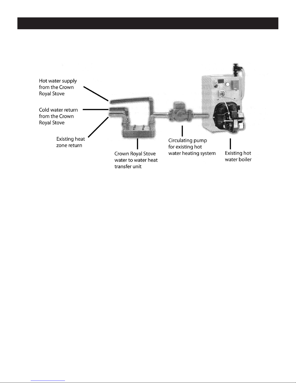
• If the central heating system is a hot water boiler system, a water to water heat exchanger is needed. The water from an
open system will contaminate the closed system if the waters are mixed together.
•It is advisable to install ball valves, isolation flanges, etc. to make the removal and the replacement components easier.
Wiring Inside the Building
• The electrical wiring must be done by an experienced HVAC technician to ensure the system will operate as desired and is
safe.
• It is recommended that the circulation pump or pumps run continuously.
• The existing forced air circulation blower needs to be wired through the circuit board to a 24 volt wall thermostat which is
dedicated for this purpose. The other wall thermostat which is for the forced air (Oil, LP, NG or Electric) is left intact. The new
24 volt wall thermostat will cause the circulation blower to run without the burners coming on. An experienced HVAC
technician needs to perform the wiring.
• The electrical for a boiler system is more complicated because the existing boiler wall thermostat is used but the burners on
the (Oil, LP, NG or Electric) boiler are not to operate when the water from the water stove is to provide heat. It is necessary to
have an experienced HVAC technician wire this configuration.
•If air conditioning is used you must add a relay DPDT to prevent the condenser from turning on when the fan is energized.
Electrical Requirements
•Electrical Rating: 120 AV Volts, 6 AMPS, 60 Hz. Wire must be rated and approved for direct burial if it is to be buried in the
same trench as the water lines. Boiler power connection box is located at rear of boiler inside back cover. Minimum supply 15
AMPS. Maximum device 15 AMPS. USE COPPER CONDUCTORS ONLY.
INSTALLATION
14
ALL INSTALLATIONS AND OPERATIONS MUST FOLLOW FEDERAL, PROVINCIAL, STATE, AND LOCAL CODES FOR WIRING, PLUMBING
AND INSTALLING CHIMNEY. ALL WORK MUST BE PERFORMED BY QUALIFIED PERSONAL ONLY.
It is recommended that piping used is able to withstand 100 PSI at 180 F, and is at least 1” (inch) in diameter. 1 1/4 “(Inch) piping is
recommended for larger systems.
The Crown Royal Stove shall be installed without interfering with the normal delivery of heated water from the original boiler.
The Crown Royal Stove shall be installed without affecting the operation of the electrical and mechanical safety controls of the
original boiler.
The Crown Royal Stove shall have provisions for preventing, or adequate water capacity within the boiler to prevent damage from
loss of circulation due to electrical power failure.
The Crown Royal Stove shall be installed without changing the function of the controls or rewiring the original boiler. A wiring
interconnection is permitted. The electrical system of both boilers shall be powered from a single branch circuit without exception.
FOR UNITS USED IN CANADA THE FOLLOWING IS RECOMMENDED:
•Operate the existing boiler periodically to ensure that it will operate satisfactorily when needed.
•Do not relocate or bypass and of the safety controls in the existing boiler installation.
•The operation of the existing gas boiler must be verified for acceptable operation before and after installation of the Crown
Royal Stove by a gas fitter who is recognized by the regulatory authority.
•Do not connect to any chimney or vent serving a gas appliance.
•Ensure the installation complies with the requirements of CAN/CSA-B365. Any changes to the installation should comply with
CSA B139 (for oil-fire), C22.1 (for electric), or CAN/CGA-B149.1 or CAN/CGA-B149.2 (for gas-fired).
EXISTING HOT WATER HEAT - INSTALLATION
15
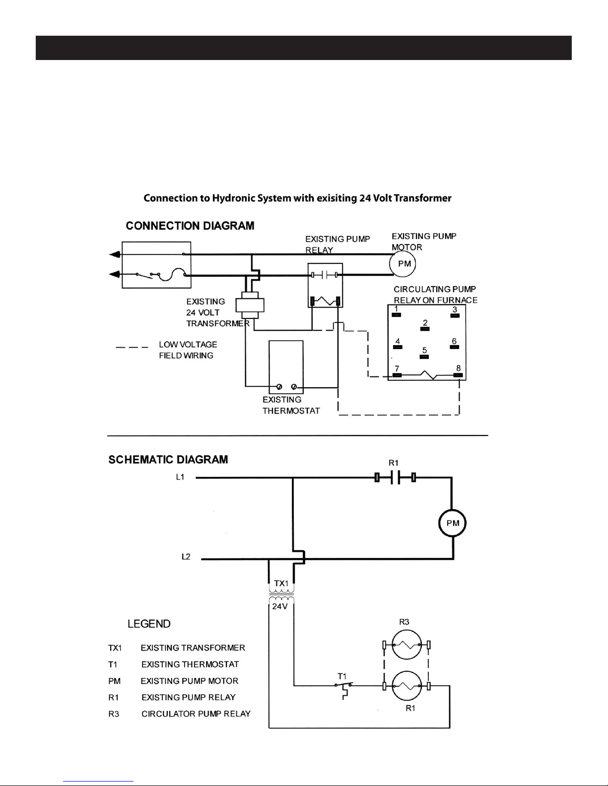
Put ‘strap on Aqua stat on the supply side of the water-line from outdoor furnace. Run thermostat wire from the ‘strap on Aqua stat
to R and G of fan control center. Run 115V power to white and black wire of fan center coil. Break one wire of gas boiler Aqua stat.
Hook one side of wire to brown wire of fan control center contact. Hook other side of gas boiler Aqua stat wire to black on fan control
center contact. Set ‘strap on Aqua stat to close at 100-120 degree.
WIRING DIAGRAM FOR GAS BOILER - INSTALLATION
16

ALL INSTALLATIONS AND OPERATIONS MUST FOLLOW FEDERAL, PROVINCIAL, STATE, AND LOCAL CODES FOR WIRING, PLUMBING AND
INSTALLING CHIMNEY. ALL WORK MUST BE PERFORMED BY QUALIFIED PERSONAL ONLY.
DOMESTIC HOT WATER
The Domestic Hot Water Flat plate Kit consists of a Water to Water Heat Transfer unit and the fittings needed to hook it up. The unit
goes on top of the domestic hot water heater and is connected as shown below.
EXISTING FORCED AIR
A water to air heat exchanger is inserted in the existing plenum. In most cases the heat exchanger is placed in a horizontal position,
keeping all four sides level. The air must be forced through the finned area of the heat exchanger evenly. The hot water line coming
from the hot - water tube enters the bottom fitting of the heat exchanger and exits the top fitting, which returns to the furnace. If the
plenum is too large or too small, it must be altered to fit the heat exchanger properly.
After installation of the add-on water to air exchanger, the air flow must be increased to fuel the furnaces, electric furnaces, and
electric/gas furnaces. Methods of doing this are:
BELT DRIVE SYSTEM: Blower pulleys and motor pulleys may be changed but the electric current flowing through the motor shall not
exceed the nameplate rating. (A blower motor or larger power may be used.)
DIRECT DRIVE SYSTEM: The motor shall not be changed, however the speed of the motor may be increased.
Water return to
Crown RoyalStove
Hot Water
from
Crown RoyalStove
THE HEAT EXCHANGER: Air blows through the heat exchangers grill taking the heat from the water heated grill and blowing it into
your existing ductwork.
THE HEAT EXCHANGER: Air blows through the heat exchangers grill taking the heat from the water
heated grill and blowing it into your existing ductwork.
CAUTION!!! When installing heat exchangers do not tamper with existing controls. Wiring to existing blower can be
done with a line voltage or low voltage thermostat.
NOTE: Wire thermostats according to directions provided by the manufacturer.
DOMESTIC HOT WATER & FORCED AIR - INSTALLATION
17

18

Brazed Plate Water to Water Exchanger
The Brazed Plate water to water exchanger can be installed on either the cold side or the hot side of the
hot water heater. If installed on the cold side, the hot water heater needs to be left on to maintain the
temperature in the hot water heater. If installed on the hot side, the hot water heater needs to be turned
off and the hot water heater is now a reservoir.
DOMESTIC SIDE BOILER SIDE WITH BYBASS
PART NUMBER
DESCRIPTION
PX4-12NL
¾” PEX X MALE ADAPTER (NO LEAD)
15-002
¾” BALL VALVE (NO LEAD) FIP X FIP
110-164
¾” UNION ELBOW IPS
304-003
¾” X 2-1/2”RED BRASS NIPPLE
110-168
1”UNION ELBOW IPS
305-003
1”X 2-1/2”RED BRASS NIPPLE
15-003
1”BALL VALVE (NO LEAD) FIP X FIP
PX4-16 NL
1”PEX X MALE ADAPTER (NO LEAD)
PXT-16 NL
1”PEX X 1”PEX X 1”PEX TEE (NO LEAD)
PXBAL-16 NL
1”PEX X 1”PEX BALL VALVE (NO LEAD)
BRAZED PLATE - INSTALLATION
19
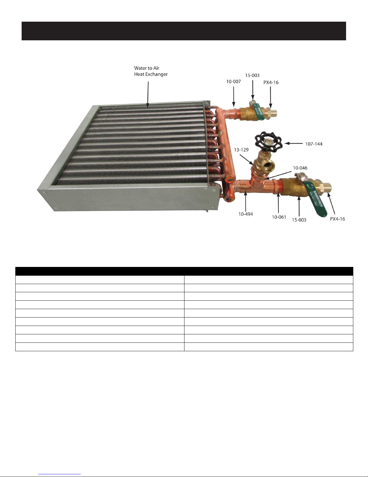
Water to Air Heat Exchangers are for use in your hot air plenum of your existing forced air furnace, to
transfer heat into your existing forced air system.
PART NUMBER
DESCRIPTION
10-007
1-1/4”COPPER ADAPTER C X FEMALE
15-003
1”BALL VALVE FIP X FIP
PX4-16
1”PEX X MALE ADAPTER
107-144
¾” MALE BOILER DRAIN MNPT
13-129
1”X ¾” BRASS HEX BUSHING
10-046
1”COPPER FITTING ADAPTER FTG X FEMALE
10-494
1”X 1”X 1”COPPER TEE
10-061
1”COPPER ADAPTER FTG X MALE
15-003
1”BALL VALVE FIP X FIP
WATER TO AIR SETUP - INSTALLATION
20
This manual suits for next models
1
Table of contents
Other Crown Royal Stoves Stove manuals


Popular Stove manuals by other brands

HearthStone
HearthStone Stowe DV 8321 Owner's manual & installation guide

Beldray
Beldray EH0690 instruction manual

Jydepejsen
Jydepejsen EOS user manual

Morsø
Morsø 2800 Instructions for installation and use

Earth Stove
Earth Stove 1003C Installation and operation manual

Valor
Valor Willow Operating & installation manual


