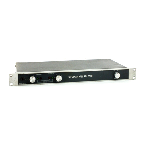
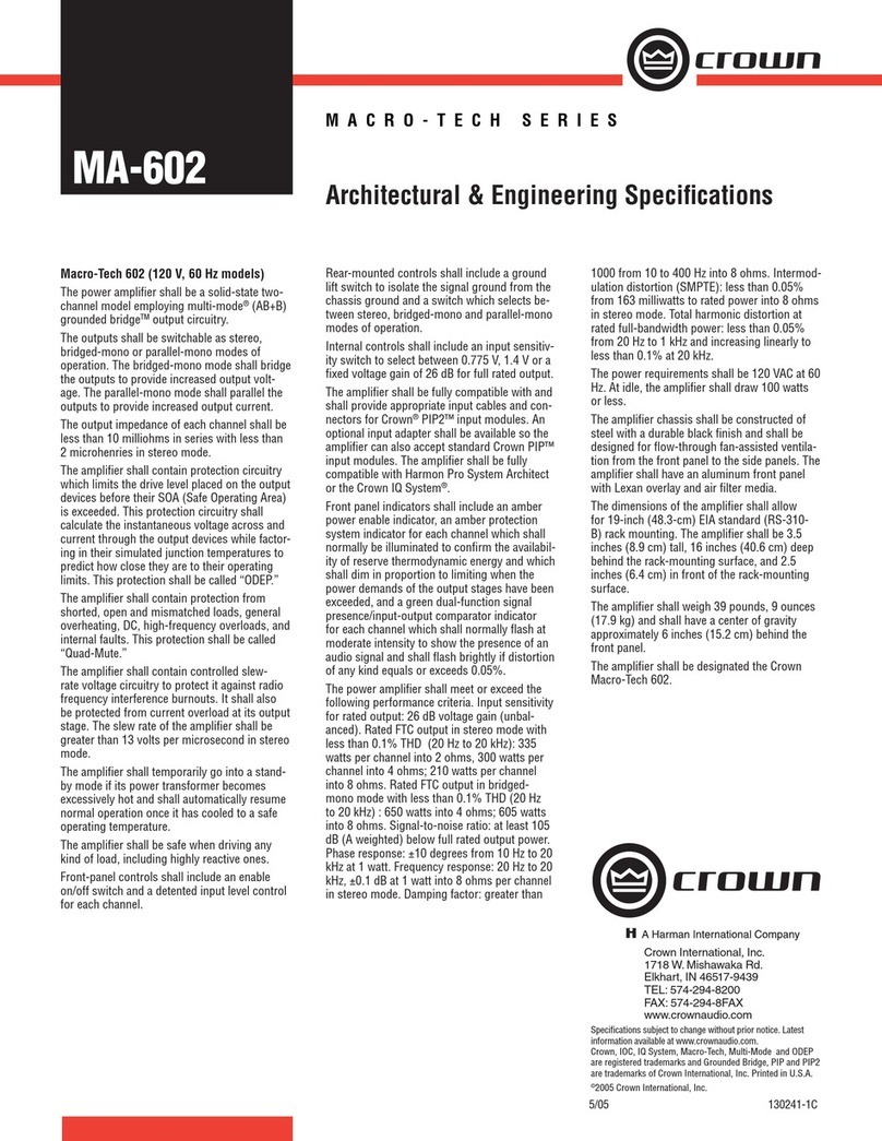
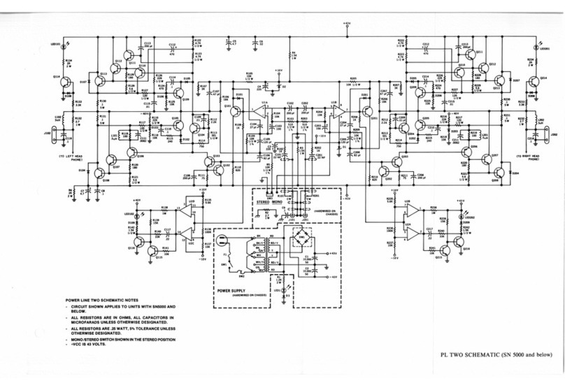
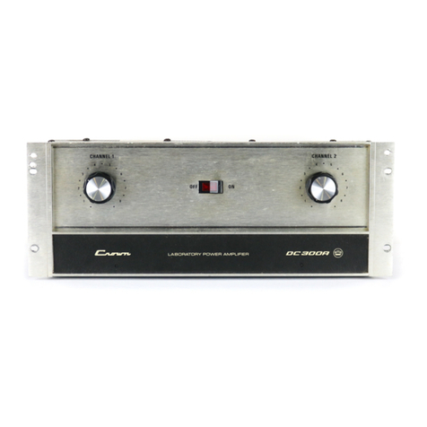
Crown D-60 User manual

www.SteamPoweredRadio.Com
I
I
I
I
I
I
I
I
I
I
I
I
I
I
I
I
I
I
I
FULL
THR
EE-
YEAR
WARRANTY
THE
WARRANTY
For
a period
of
three
yea.rs from
the
date
of
delivery
to
the
original Purchaser, Crown
Int
ernational, Inc.
(hereinafter
"Crown")
warrants
to
the
original
and any
subsequent purchaser
of
each new Crown
component
(except Crown recorders)
that
it
is free from
any
substantial defects
in
materials
or
workmanship
and
that
it
will
meet
or
exceed all advertised specifications
for
such
component.
NOT
IFICATION
OF
CLAIMS
The
Purchaser
must
notify
Cr
own
in writing
at
the
address
set
forth
below
of
any
claimed breach
of
war•
ranty.
Such notification shall
be
delivered
to
Crown within a reasonable length
of
time
llfter
the
discovery
of
the
claimed
defect
and
not
later
than
ninety
days
after
expiration
of
the
warranty
period. Within
ten
business days
after
r
eceipt
of
the
notification, Crown will request Purchaser
to
dd
iver
the
component
to
llD
authorizedservice
agency
for
repairs
or
will deliver
to
Purcl:iaser
written
authorization
to
return
the
component
to
Crown
for
fac-
tory
wuranty
service.
If
Crown's
(or
its
authorized
service agency's) inspection reveals
that
there
has
been
a
breach
of
the
warranty,
Crown
(or
its 11uthorized service dealer) will initiatecorrective repllirs within
thirty
days
after
receipt
of
the
component.
All
components
must
be
shipped
in
original
factory
pack, which
if
needed, may
be
obtained
from Crown free
of
charge.. All such repairs, including labor,
pa
.
rts
llOd
shipping costs within
the
United
States
wiJI
be
made
at
Crown's
expense. PurchllSCr
must
beu
the
expense
of
sh
ipping
the
component
between
any
foreign
country
llnd
the
part
of
entry
in
the
United States,
and
all taxes,
duties
and ot
her
custom's
for
such foreign shipments. WARRANTY
If
the
repairs
made
by
Crown
or
the
authorized
service dealerarc
not
satisfactory, Purchaser
sho
uld immcdi·
atdy
give
written
notification
to
Crown.
If
the
defect
or
malfunction remains
after
a reasonable
number
of
attempts
by
Crown
to
remedy
the
defect
or
malfunction,
the
Purchasershall
then
have
the
option
to
elect
either
a r
efund
for
or
replacement
without
charge
of,
the
Crown
component.
The
refund
shall
be
an
llmountequal
to
the
actual purchase price,
not
including any interest, insurllOce, closing costs llnd
other
finllnce chllrge, minus
reasonable depreciation
on
the
component.
If
a
refund
is demanded,
the
PurchllSCr
must
make
the
defective
or
malfunctioning
component
available
to
Crown free
and
clear
of
llll liens or
other
encumb
rances. ShouldCrown
fail
to
meet
its
obli.gation hereunder, PurchllSCr
may
sue Crown
to
secure
its
compliance
with
this
warranty. ANY
SUIT BY PURCHASER
FOR
BREACH
OF
THIS WARRANTY MUST BE FILED WITHIN
FOUR
(4) YEARS
OF
THE DATE
OF
DELIVERY
TO
THE
ORIGINAL PURCHASER.
WARRANTY VIOLATIONS
CROWN SHALL H
AVE
NO RESPONSIBILITY IF
TH
E COMPONENT HAS BEEN SUBJECT
TO
MISUSE,
ACCIDENT, NEGLECT
OR
FAILURE TO COMPLY WITH NORMAL MAINTENANCE PROCEDURES
OR
IF
THE
SER
I
AL
NUMBER HAS BEEN DEFACED, ALTERED
OR
REMOVED;
NOR
WILL CROWN ACCEPT
RESPONSIBILITY
FOR
OR
RESULTING FROM IMPROPER
ALTERAT
IONS
OR
UNAUTHORIZED
PARTS
OR
REPAIRS. THIS WARRANTY DOES NOT COVER ANY DAMAGE
TO
SPEAKERS OR ANY
OTHER
CONSEQUENTIAL DAMAGES RESULTING FROM BREACH
OF
ANY WRITTEN
OR
IMPLIED
WARRANTY. MODIFICATIONS
OF
EQUIPMENT
Crown reserves
the
right
to
modify
or
chllDge
equipment
in
whole
or
pan
at
llDY
time
prior
to
delivery thcrof,
in
order
to
include therein electrical
or
mcchllDical improvementsde
emed
appropriate
by
Cr
own,
but
without
in-
curring llny liability
to
modify
or
chllnge
any
equipment
previously delivered,
or
to
supply new equip
ment
in
accordllDce
with
llDY
ellrlicrspecification.
WARRANTY AL
TERAT
IONS
NO
PERSON HAS
THE
AUTHORI
TY TO
ENLARGE, AMEND
OR
MODIFY
THI
S WARRANTY. THE
WARRANTY IS
NOT
EXTENDED
BY
THE
LENGTH
OF
TIME
WH
ICH THE PURCHASER IS DEPRIVED
OF
THE USE
OF
THE
COMPONENT. REPAIRS AND REPLACEMENT PARTS PROVIDED PURSUANT
TO
THIS WARRANTY
SHALL
CARRY ONLY
THE
UNEXPIRED
PORT
ION
OF
THIS WARRANTY.
CR
OWN
INTERNATIONAL, INC.
1718
West Mishawaka Road, Elkhart, lndillDa 46S
14
OWNER
----------------------------------
ADDRESS
________________________________
_
THIS STATEMENT
OF
WARRANTY SUPERSEDES
ALL
OTHERS
CONTAINED IN THJS MANUAL

www.SteamPoweredRadio.Com
I
I
I
I
I
I
I
I
I
I
I
TABLE
Of
CONTENTS
PAGE
Section 1
1.1
1.2
1.3
1.4
Section 2
2.1
2
.2
2.3
2.4
2.
4.1
2.
5
2.6
Section 3
3.1
3.2
3.3
3.4
3.5
Section 4
4.1
4.2
4.3
Section 5
DESCRIPTION
General ....................
..
..................................
..
.........................................................
....
........ 1
Specifications .............................................................................
..
....... 2, 3, 4,
5,
6, 7, 8, 9
Warranty ............................................................
..
...............................................
..
.
...
..
...... 10
Acces
so
ries .............................................................................
..
....
....................
..
.
...
..
....... 10
INSTALLATION
Unpacking ..............................................................
..
...
..
..
...
..........
...
..
..............
..
..
..
...........
11
Mounting ............................................
..
.......................
..
...................
..
.............................. 11
Normal Hi
-Fi
Installation ..........
..
.
..
.............
..
................................................................... 13
Conne
cting Output Lines ..................................................
..
.............................
..
............. 13
Mono Operation .
..
..
....
...
..
...
..
..
...
...
.......
....
.
..
...
........
...
..
.
..
..
..
.
..
......
..
......
..
....
......
..
.
..
...
..
........ 14
Connecting Input Lines ..................
..
....
..
...............................
..
........................................ 15
Connecting
Power
............................................................................................................ 16
OPERATING
INSTRUCTIONS
Controls and Adjustments ......................
..
...
..
.
..
............................................................
..
17
The Protection Mechanisms ........................................................................................... 17
Operating
Pre
cautions ..............................................................
..
..................................... 19
Load
Protection Methods
....
....
..
....
.
..
..
..
....
..
...
..
...
..
............
..
....
.
..
...
....
....
..
..
...
..
..
.
..
..
..
..
..
.....
19
Cleaning ...................................
..
.......
..
.
..
..............
..
........................................................... 20
CIRCUITRY
Principles
of
Operation .......................................................................
..
..........................
21
Test Procedures .................................................
..
..........
..
..........
...
.......
..
.....
..
..
.................
21
Service .........................................................................................
..
..
.............
..
.
..
.
..
..........
..
22
APPLICATION
NOTES
Note #1 V-I Limits of a
Load
.......................................................................................... 23
Note #2 Speaker Protection
......
...
...
..
....
..
.......
..
.........................
..
............................
...
.... 25
I
LIST
Of
ILLUSTRATIONS
I
I
I
I
I
I
I
TITLE
PAGE
1-1 D-60 Pictorial ...........................................................
....
.......
..
.....
...
.....
..
...........
..
................. 1
1-2 D-60 and
VFX-2
in Optional 5-R Enclosure ...................................
..
..
.....
....................... 10
2-1
End
-
Cap
/Bracket Mounting ..
...
..........
..
......
..
..................................................................
11
2-2 Mounting Dimensions
..
...................................................................................................
11
2-3 Normal
Hi
-
Fi
Installation .....................................................
..
..........................
...
....
..
....... 12
2-4
Rear
View
of Chassis ........................
..
...............
...
.....
.............................
..
....................... 13
2-5 Schematic for Full
Range
Electrostatic Speaker Connection
..
.................................... 13
2-6 Source Resistance and Damping Factor
vs
. Length and Size of Output
Leads
........ 14
2-7 D-60 Mono Hook-
up
...................................................
..
..
......
..
......
..
....
....
..
......
..
.
..
............ 15
2-8 Graph for
Sele
ction
of
Input Capacitor ................................
..
.
.....
...........
..
..
.................. 15
2-9
Low
-
Pa
ss Filters for
Severe
RF
at
Inputs .....................
..
..
..
.....
......
................................. 15
3-1 Operating Controls
..
.........
..
...............
'.
..
.........
..
............................................
..
.........
..
....
....
17
3-2 Graph
of
VI
Operating
Range
of
D-60 Output .........
..
....................
..
..
.......
..
..
................. 18
3-3
Fuse
Sele
c
tor
Nomograph for Loudspeaker Protection ....
..
...............
..
........................ 19
3-4
Relay-
Controlled Protector with Overload Indicator ....
...
..
............................................ 20
3-5 Turn-on-Transient Muter for
Load
Protection
..
.......................................................
..
..
..
20
Schematic
www.SteamPoweredRadio.Com
I
I
I
I
I
I
I
I
I
I
I
I
I
I
I
I
I
I
I
Section 1
DESCRIPTION
1.1
GENERAL
FIG.
1 -1
INTEGRATED CIRCUIT STEREO
D-60
AMPLIFIER
The D-60 is a dual-channel medium power ampli-
fier for ultra-low distortion amplification from
5Hz to 20KHz with operation into loads
of
4 ohms
and higher. The
unit
features extremely low har-
monic and intermodulation distortion, very l
ow
noise, highest "damping factor," and quality parts
and workmanship. The
unit
may
be
wired to pro-
duce a balanced 25 volt monaural output. The am-
plifier is fully protected against mismatched and
shorted loads by a resetting
V-1
(volt-ampere)
limiter having no obnoxious muting or program
delays.
The power supply features large computer-grade
filter capacitors.
1
A total of 24 discrete transistors, 1 linear
IC
(dual
op amp), 14 diodes and 1 bridge rectifier are uti-
lized in a
CROWN-pionee
red Class
AB+B
output
circuit The effective number of semiconductors
is 40 transistors and 24 diodes
Th
e input voltage-amplifiers, (I
C),
are powered by
two voltage-regulated supplies. This results in
complete channel-to-channel isolation and inde-
pendence from line voltage variations.
Two level controls are mounted
on
the front panel
to allow balancing and optimizing of system levels.

www.SteamPoweredRadio.Com
2
1.2
SPECIFICATIONS
1.2.1
STEREO
SPECIFICATIONS
I
I
I
Output Power
28
watts per channel mm1mum RMS (both channels oper- I
ating) into an8 ohm loadovera bandwidthof
20Hz-20
KHzata
rated RMS sum total harmonic distortion of
0.05
% of the fun- I
damental output voltage.
Frequency Response :t.0.ldB 20Hz-20KHz
at
1 watt into 8 ohms;
.t.J.2d8 5Hz-100KHz at 1 watt into 8
ohms
.
..
lKHz
<Power ,
35
watts
RMS
into8
ohms
,perchannel, both channelsoperating, 0.1%total harmonic
distortion.
Harmonic Distortion Less than 0.
001
%from 20Hz-400Hz, and increasing linearly
to
0.05%
at
20KHz at 28
watts
RMS
per channel into 8 ohms.
I.M. Distortion ·
(60Hz-7KHz 4:1)
Slewing
Rate
Damping Factor
Le
ss
than
0.05
%
from
0.01 watts
to
0.25watts,and lessthan0.01%from0.25watts to
28 watts into 8
ohms
per channel.
6voltspermicrosecond (slewing rate is
the
maximum
value
of
the
first
derivativeofthe
output
signal,
or
the
maximum
slope
of
the outp
ut
signal).
Greater than 400,
DC
-400Hz
into
8
ohms
.
Output Impedance Less than
15
milliohms in series with less than 3 microhenries.
Load Impedance
Voltage Gain
Input Sensitivity
Output Signal
Rated for 8 ohm usage; safely drives any load including completely reactive loads.
20.6:t.2%
or
26
.3:t.
0.2
d8
at
maximum gain.
0.75
volts .:2% for
28
watts into 8 ohms.
Unbalanced, dual channel.
I
I
I
I
I
I
I
I
I
I
I
I
I
I

www.SteamPoweredRadio.Com
I
I
I
I
I
I
I
I
I
I
I
I
I
I
I
I
I
I
I
3
1.2.2 MONAURAL SPECIFICATIONS
Ou
t
put
Power
56
watts
minimum
RMS
into
a 16
ohm
load
over
a
bandwidth
of
20Hz-20KHz at a
rated
RMS
sum
total
harmonic
distortion
of
0.05%
of
the fundamental output
voltage.
Frequency
Response
±.
0.2dB 20Hz-20KHz, 1 watt,
16
ohms.
±.ldB 6Hz-50KHz, 1 watt, 16 ohms.
lKHz
Power
70 watts
RMS
into 16 ohms.
Harmonic Distortion
Less
than 0.001% from 20Hz-400Hz and increasing linearly to 0.05%at20KHz at 56
watts into
16
ohms.
I.M
. Distortion
Less
than 0.05%from 0.01 wattsto0.25watts,and lessthan 0.01%from0.25watts
to56
watts into 16 ohms.
Slewing
Rate
12 volts per microsecond.
Damping Factor Greater than 400,
DC
-400Hz into 16 ohms.
Output Impedan
ce
Less
than 30 milliohms in series with less than 6 microhenries.
Load
Impedance
Rated
for 16 ohm usage, safely drives any load including completely reactive
loads.
Voltage
Gain
41.2±2%or 32.3±.0.2dB at maximum gain.
Input Sensitivity 0.75 volts ±2%for 56 watts into 16 ohms.
Output Signal Balanced, single channel.

www.SteamPoweredRadio.Com
4
1.2.3
GENERAL
SPECIFICATIONS
Hum and Noise
(20Hz-20KHz)
Phase
Response
Input Impedance
Amplifier Output
Protection
Overall Protection
DC
Output Offset
(Shorted Input)
Turn-on
Circuit
Power
Supply
Power
Requirements
Heat Sinking
Chassis
Controls
Connectors
Dimensions
Weight
Finish
106dB below rated output.
+10, -15° 20Hz-20KHz
at
1 watt.
25K ohms
±30
%.
Short, mismatch,and open
circuit
proof.V-1
limiting
isinstantaneouswith
no
annoy-
ing
thumps, cutout, etc.
AC
line fused. Controlled slewing rate voltage amplifiers protect overall amplifier
against
RF
burnouts.
Input
overload protection isfurnished byinternal resistanceat
inputs
of
amp.
10 millivolts
or
less.
Instantaneous, with
minimum
thumps
and no program delay.
Wideband
multiple
feedback loopdesign utilizingone linear
IC
(dual
op
-amp).Total
equivalent
of
40
transistors, 18 signal diodes, 2 zeners, and 4 rectifier diodes.
Special design low profile transformer. Computer grade filter capacitors.
Two
regulated supplies for complete isolation and stability.
Requires 50Hz-400Hz
AC
on 100, 120, 200, 220,
or
240
volts ±10% operation
Draws
15
watts
or
less on idle, 120 watts
at
56
watts total output.
The entire amplifier isused as a heatsink. Frontpanel extrusion acts as a heatsink
along with
the
chassis covers.
Aluminum chassis construction for maximum heat conduction and minimum
weight.
Two
input
level controls on front panel with powerswitch and pil
ot
light. A mono-
stereo switch is located next
to
the
input
jacks on the rear panel.
Input -
1/4
inch phone jack.
Output -Color-coded binding posts with stereo
1/4
inch earphone jack on front
panel.
AC
Line -Three-wire (grounded) male connector on 5 foot
minimum
cable.
17inches long,8¾inchesdeep, and 1
¾ inches high (8 inchesdeepfrommounting
surface). 19 inch standard rack mounting hardware included.
10 pounds net weight
Satinized aluminum front panel with gray suede Lexan insert.
•
I
I
I
I
I
I
I
I
I
I
I
I
I
I
I
I
I
I
I

www.SteamPoweredRadio.Com
I
I
I
I
I
I
I
I
I
I
I
I
I
I
I
I
I
I
I
+l
0
"'"
-1
-2
-3
◄
TO
DC
+5
0
-5
+5
DB 0
-5
+5
0
-5
+20
+10
0
PHASE
SHIFT
-
10
(degrees)
-20
-30
-
40
--
----
~
MIN,
L
10
100
l
I
RE
1)
CY
t,
,J
''
'
''
"
lK
FREQUENCY
(Hz)
I
ES
I>( ~
NOii
Ir
I~
._
I
~
t;tc
l'(C.
:SI
••
{pe
..-
C
10
-..,~
-
......
_
41
hm
ph,
I~
I
.,
it
:
8 C
hm
ph,
I~
thif
--
_
...
r
"'
HF
DEi
AV
Al~
1111
10
DI~
CLb.~Imi
pf,
Of
i1
/8
I
t::,.
L
.
""'"'
'' f V • --
.,.
100
2u sec del1y
1.
75
u ~-
~el
y
...
.
vu
......
-
11
. phase 1
hift
=1 3! l
100
I
lK
FREQUENCY
(Hz)
'n1
Ill
\I l
i>
lw
o 1tpu
(11
pi
iH
delay
lK
FREQUENCY
(Hz)
:al
>I
5
iii;
-
=::::
...........
~
....
Ill,
C:I
l0K
I
n;
II
1
IJ
I
l0K
,ASE'
RI:
Cl:
1y
level
bekl
w~
-...::::
l0K
"
I"-
16
ohms
8 ohms
4ohms
l00K
40w
30w
20w
l00K
l
,.,
NI
=
'
,a
im
Jm
I
~
~'
\\
I~
I\
16A
,
.A
1
4A
l00K

www.SteamPoweredRadio.Com
6 I
.1 I
NOMINAL HARMONIC DISTORTION I
.
01
I
D
ISCLOSU
RE
PROHIBITED I
e
ff
ective Nov. 4,
197
4
.001 I
10
100
lK
lOK
100K
I
FREQUENCY
(Hz) I
I
.1
.
08
I
.
06
INOMINAL INTERMODULATION DISTORTION
.
04
.
02
I
I.M. 0
% I
.
06
TEST
I
.
04
INSTRUMENT
RESIDUAL
0.
001
%
.
02
DISCLOSURE {typ) I
PROHIBITED
0 e
ff
ective Nov. 4, 1
97
4
.
06
I
.
04
.
02
I
.
01
.1 1
10
100 I
POWER
OUTPUT
(Watts) I

www.SteamPoweredRadio.Com
I 1 -7
.,
I
~
~
~(
,,-
I~'
OU1
Pl
11
I~
~
DAI'
Cl I
.4
... /
,,,
I .1
~'
I
IZol
(Ohms)
r
,,
~,,
/
I .01
--
---~
I -
'
I .004 l
I
1 10 100
lK
l0K
100K
I 70
FREQUENCY
(Hz)
I 60
I -
...
·-
,- "'
I I "
P.E.
--
--
-
....
~i.
·-·
·-
·
~
\
I
(per
cent)
50
--
~
be
or
di
I>~~
,
I 40
I 30
I
~
MialN4
I
ti
~
I
"S:-1='
Ill'
I
a:
N ,.. w '
8
ohJs
I u : 00
120
VAC
Ln
r
>A
IN
l
I 10 100
lK
FREQUENCY
(Hz)
l0K
lOOK
I 1000 I
I
..
..
"
I 100
'-
~
NOi
1111
II
I
I
II•
-.
\0
'""
.,
..
'
""
..
I 10 '
~
I 10 100
lK
l0K
l00K
I
FREQUENCY
(Hz)

www.SteamPoweredRadio.Com
8
90
80
60
IJ.o
(DEGREES)
DB
below
30w
40
20
0
-10
-
70
-80
-
90
-
100
-
110
400
100
nV
/
VHz
10
l
IIOMII u
I
I
..
,
r\
• I
. -
._
NO
~,
~.
N
01:~
........
~
.,
p
--
- ~ I
I
I
1
..
,.,_
DUT
~L
T
~
I
I
...
~-
10
~
...
""'
"'~
!I!:
10
I
,A
•
l')
I
10
I l
I
,--
--
I
~
~
""'---
/
,!~
•E
Ar
G
LE
i/
i
'
I/~
/,
I
....
tr
I
100
lK
l0K
FREQUENCY
(Hz)
I I III
,I I
..
I / ,
CH2l
EVI
L U I C t V
I -
·""
~
~
~ '
~
.)
"~
I
I
....
,
/ 1 I ; I
_ ,
~
I
-I '
I
100
lK
l0K
FREQUENCY
(Hz)
LINE
RE
,u
Ef
IC
'
~
RMOI\
ICS
r"LUI
,
cu
[
I\.
I 1 1111 1
1n
....
....
1
I\Uim
TOTA
IS
E(
UIV
"
~
TTO
.
3lV
INPU'
NC
IC
:
,,
II
~M
....? wn.
.,.
'A
..
i
I
I
100
lK
lOK
F~EQUENCY
(Hz)
~~
lOOK
lOOK
lOOK
I
I
I
I
I
I
I
I
I
I
I
I
I
I
I
I
I
,,
I

www.SteamPoweredRadio.Com
10
1.3
WARRANTY
CROWN
guarantees this equi
pment
to
perform
as
specified.
CROWN
also warrants the
com
ponents
and workmanship ofthis equipment
to
be free from
defectsfor a period
of
3years fromdate
of
purchase.
This warrantydoes
not
extend
to
fuses,and
/o
r
com
-
ponent
or
equipment damage
due
to negligence,
misuse, shippingdamage
or
accide
nt
;
or
if
the serial
number has been defaced, altered
or
removed.
A copy of the FULL THREE-
YEAR
WARRANTY
is
in
-
cluded with this manual. The
WARRANTY
issubject
to the conditions contained therein. Upon receipt
of
the registration form,
CROWN
will issue a
WAR-
RAN
TY TI
TLE.
This title applies
to
the original end-
purchaser
as
well as subsequent purchasers.
You,
the purchaser(s), are responsible
for
accurate,
complete records (sales slips, invoices, etc.) for
FULL coverage!
1.4
ACCESSORY
EQUIPMENT
1.4.1
"R
"
SERIES
WALNUT
ENCLOSURES
Rich oiled-walnut veneers, highlighted with flatback
trim, accentthe
D-6O
when installedon ashelf
or
ta-
ble in an "
R"
series enclosure. The design
of
these
enclosur
es
permits vertical stacking
of
several com-
ponents. Several cabinet sizes are available which
accommodate
multiple
components in one enclo-
sure. Available sizes are 5-R, 7-R, 10-R, and
14
-R.
1.4.2
VFX
-2
The
CROWN
VFX-2
is a dual-channel variable elec-
tronic filter-crossover. When used with a power
amplifier
it
can greatly add
to
thetotal system capa-
bility.
In
combination with the D-6
O,
the
VFX
-2 adds
several convenient useful functions.
The connections are made with the
VFX
-2 quickly
and easily.
If
abalanced lineistobeused withtheun-
balanced
input
of
theD-6Othe
VFX-2
canserveasthe
interface. While maintaining these functions the
output
can be shaped
by
selecting variable high-
pass,lo-pass,
or
band-passfilters.
As
a
filter
,the
VFX-
2 can be used
as
acrossover
or
ahead
of
severalam-
plifiers in a
bi
-
or
tri
-amped system.
FIG. 1-2
D-60
AND
VFX-2
IN
OPTIONAL
5 -R ENCLOSURE
I
I
I
I
I
I
I
I
I
I
I
I
I
I
I
I
I
I
I

www.SteamPoweredRadio.Com
I
I
I
I
I
I
I
I
I
I
I
I
I
I
I
I
I
I
I
2
.1
UNPACKING
As
soon
as
the amplifier shipment is received,
please inspect for any damage incurred in transit.
Since the unit was carefully inspected and tested
at
the factory,
it
left the factory unmarred.
If
dam-
age
is found, notify the transportation company
immediately. Only the consignee may institute a
claim with the carrier for damage during ship-
ment. However,
CROWN
will cooperate fully in
such
an
event.
Be
sure to
save
the carton
as
evi-
dence
of
damage for the shipper's inspection.
Even
if
the
unit
arrived in perfect condition -
as
most do -
it
is advantageous to save the packing
materials. They will prove valuable in preventing
damage should there ever be occasion to transport
orship the uni
t.
Notethecarton and internal pack-
each
is
designed for protection during transit.
Do
not ship the unitwithout this factory pack!
2.2
MOUNTING
The D-60 is shipped with end-caps installed.These
end-caps are used
for
custom panel mounting.
Insucha
"c
ustominstallati
on
,"installasolidshelf,to
support the amp. Itshould be flush with the bottom
edge
of
the required 17" wide x 1¾" high panel-cut-
out. The shelf should have a hole cutin ittoallow
air
tocirculate freely to thelouvers inthe bottomcover.
Angle brackets supplied with the D-
60
are used for
rack mounting and for installation into the
5-R
or
other larger
CROWN
"rack" cabinets. Align these
angle brackets
on
the
unit
to matchthe holeswhich
held the end bars.
Use
6/ 32 x ½ socketcap screws
(Note: Socket screws may look as though they are
crossthreading
but
will straighten approximately
halfway through).
See
figure 2-1.
IND
IIACKIT
] 0
I
I
I
I
I
'
1111()
.:i
I
l 0
FIG.
2-1
END-CAP/BRACKETMOUNTING
11
Section
2
ISTILLITION
Sufficient ventilation
must
be provided forthe unit.
Thismeansthat
air
must
be
allowed
tocirculateover
the chassis
to
preventoverheatint. Applications -
other than "Hi-Fi" -requirin1 Iona, sustained sig-
nals
at
hi&h power-levels may require the use
of
a
coolin1 fan. When rack mountin1,
it
isa
1ooct
prac-
tice to allow a 13
/4"
spaceabove and below theunit.
(See
fi1ure 2-2 for mountin1 dimensions.)
~I
oo
o 0 0
Id
..
ilo
o o 0 0 Ii]!
'-------
..
I
1-
L-,.__---.1..l---,C~
..
'ff
@
l_..LJ·~-·
_1_11_,1_11
_111_1
i_11
_111--->..:1
o:.<-+,i
~-~
·~
h
•
•
l.,..1
, 0
l
•
i •
o@
l+------k'-----1
FIG.
2-2
0 -
60
MOUNTING DIMENSIONS

www.SteamPoweredRadio.Com
POWER
AMPLIFIER
PROTECTION
SYSTEMS
PROTECT
AMPLIFIERS,
BUT
NOT
SPEAKERS!
3
to
2
wire
adapter
Switched
Outlet
TPOT
MA
IN TAN
2 1 2 1
~l
HT
@)@
~II
GH
T~
0
ro
'2'
O
TO
IBI
I
ICO
I 0 U
IN,U
T
NP
OT
---
Shielded
Audio
Cables
Tie
RCA
Pin
-
to
-¼
" Phone
Power
Cable
MONO
-STEREO
SWITCH
+
Right
Speaker
MOP
(Dual
Banana)
Plugs
Not
e!
IN
-LINE FUSES
FIG. 2-3
NO
RMAL HI-Fl INSTALLATION
YOU,
AND
/
OR
YOUR
SPEAKER
MANUFACTURER
ARE
RESPONSIBLE FOR SPEAKER PROTECTION
+
Left
Speaker
I
I
I
I
I
I
I
I
I
I
I
I
I
I
I
I
I
I
I

www.SteamPoweredRadio.Com
I
I
I
I
I
I
I
I
I
I
I
I
I
I
I
I
I
I
I
2.3
NORMAL
HI-Fl
INSTALLATION
1.
Two-conductor speaker cables must connect to
the
OUTPUT
dual binding posts using terminal
lugs, tinned ends,
or
"banana" plugs.
2.
Since the 0-
60
is a "basic amplifier," the main
outputs of the control-center or "preamplifier"
must
be
connected via shielded audio-cables to the
two jacks marked I
NPUT.
Use
RCA-pin at preamp
and standard ¼ in. phone-plug at the D-60.
The
two cables should be tied parallel along their
entire length using the accessory cable ties.
3. U/ L requirements prefer a 3-wire
AC
power
conne
c
tor
; however,
proper
connections to a
switched outlet on the control center requires the
use
of a 3-to-2 wire adapter.
NOW
, plug the
AC
into a
S'!'it
c
hed
outlet
on
the control center.
4.
Your Control Center may now
be
turned on.
Then
advance the 0-60 Input-Gain Controls about
½
-open
(150° clockwise).
When
using the
CROWN
IC
-150A Control-Center,
the
VOLUME
should attain almost full rotation
(2
to 4 o'clock) for loudest "concert-hall" volume.
If at 3 o'clock the volume
is
low, increase the D-60
input gain controls;
if
too
high,
de
c
rease
the D-60
gains.
To assure maximum enjoyment and full speaker
protection, read the following detailed sections on
OUTPUTS,
I
NPUTS
and Chapter 3-0PERATION.
2.4
CONNECTING
OUTPUT
LINES
Input and output connectors
are
located
on
the
chassis
as
shown in
Fig
. 2-4.
FIG.
2-4
REAR VIEW
OF
CHASSIS
13
It
is
always wise to remove power from the unit
and
turn the input level controls off while making
connections, especially
if
the load is a loudspeaker
system. This will eliminate any chance of loud
blasts.
CROWN
is not liable for damage incurred
at any transducer to its being overpowered! The
use of speaker fuses is recommended.
Before making connections,
it
is recommended
that the operator familiarize himself with the am-
plifiers protective system.
See
Section 3.2.
Sec
-
tion 3.3 entitled "Operating Precautions" should
also
be
read.
Because the output wire gauge and length raises
the
resultant
source impedance or lowers
the Damping Factor
by
adding series resistance,
the nomograph
(Fig.
2-6)
is
provided for wi
re
se
-
lection.
For
dynamic moving-coil loudspeakers
the value
RL
should preferably
be
that measured
by
an
ohmmeter across the voice coil, rather than
the manufacturer's
rating
.
For
electrostat
ic
speakers
and
such, the manufacturer's rated im-
pedance should be used for
RL
.
If the load (matching transformer, inductance,
or
full-range electrostatic speaker system) appears
as
a short-circuit at low frequencies, a large non-
polarized capacitor (paralleled with a resistor)
should be placed in series with the load.
4n
,
20
W I
,,_ I
A-.
+ I
,~-
fu
ll
.__.
Output
....
,
.....
tic
S
90
·
7M
.... I
r~
,.......,._
110
VAC,NJl
l
~
.......
,
...
Ir>
·--,
GND
'--
FIG. 2-5
SCHEMA
TIC
FOR FULL RANGE
ELECTROSTATIC SPEAKER CONNECTION
For electrostatic speakers
(if
the manufacturer
has
not provided a capacitor)
an
external non-
polar capacitor of 590-708 mfd and 4 ohm power
resistor should
be
placed in series with the plus
(+) speaker lead. This will prevent large
low-
frequency currents from damaging the electro-
static transformer or from unnecessarily acti-
vating the D-60's protective system.
An
effective

www.SteamPoweredRadio.Com
14
40 .
04
RL
RL
.A>6
Rs
LOAD
Rs SOUICI
ANNEALED
30
.1
RESISTANCE
DAMPING
RESISTANCE
COPPER
(e
hfflsl F
ACTOR
(eh..,,)
2-COND,
WIii
100
(AWO)
20
,,
..
,,
.4 s
-•2•
10
so
.
24
...
~
••
-•22
15 «
20
'l
'
20
10
s 2
10
2000
9 ,
(;
2 4
5000
I .s -
•4
•
•2
7
-•
o
10
-•oo
6
.1
-=•oooo
.OS
s
20
4
40
.01
FIG.
2-6
SOURCE RESISTANCE
and
DAMPING
FACTOR
VS.
LENGTH
and
SIZE
of
OUTPUT LEADS
test
to
determine if such parts are needed is to
measure the
DC
resistance between the output
terminals with an ohmmeter. If the resistance
is
less than 3 ohms, the parts should be added as
shown schematically in Fig. 2-5.
When
selecting connectors
for
the load (speaker)
end
of
the output lines, the following general pre-
cautions apply (with all power connectors):
1. A male plug, carrying signal,
must
not
be on
the far end
of
the line where
it
can be ex-
posed, giving rise
to
both shock and short-
circuit hazards.
2. Connectors which
might
accidentally cause
the two channels
to
be tied together
during
makingand breaking
of
connection should not
be
used.
3.
Connectors
which can be plugged into
AC
power receptacles should
ne
ver be used.
4. Connectors having low-current carrying ca-
pacity are "verboten."
5. Connectors having any tendency to short,
or
having shorted leads, are unadvisable.
2.4.1
MONO
OPERATION
A mono-stereo switch on the rear panel adjacent
to
the
input
jacks, allows the D-
60
to
be operated nor-
mally(stereo)
or
in mono,with nointernal modifica-
tion.(
See
figure 2-7.) When in themonoposition, the
inputcircuitry
of
the D-
60
ischanged sothatthetwo
amplifiers are "added" for monooutput.
(See
mono
specifications, page 3).
Care mustbetaken in the externalhook-
up
toassure
proper operation. Proceed
as
follows:
1. The input line should be plugged into the chan-
nel 1 input jack. The level is adjusted with the
Channel 1
input
level control.
NOTE
:The Channel 2 inputjackand level control
arenotdefeated inthe Mono mode. However, the
Channel 2 inputshould notbe used inthis mode.
If
a Channel 2
input
is
added
to
the Channel 1
input, distortion mayresult.
If
Channel 2 inputis
used alone, very low poweroutputwill result. For
best results unplug the input
to
Channel 2 when
operatinR Mono.
I
I
I
I
I
I
I
I
I
I
I
I
I
I
I
I
I
I
I

www.SteamPoweredRadio.Com
I
I
I
I
I
I
I
I
I
I
I
I
I
I
I
I
I
I
I
2. Connect output lines as per the following draw-
ing, Figure 2-
7.
Theoutputfromthe D-60inMono
is
BALANCED
and is isolated from the c
ha
ssi
s,
and
fr
om the input grounds to the D-60.
CAUTION:
Be
certain thatall equipment(meters,
switches,
et
c.) connected to the Mono output
lines
is
balanced. Both sides ofthe line must
be
totally isolated from the inputgrounds, to the D-
60.
If
this is notobserved, severe
os
cillati
on
may
result.
FIG.
2-7
D-
60
MONO
HOOK
-UP
2.5
CONNECTING
INPUT
LINES
Connecting the inputs will require observance
of
three basic precautions: Undesirable
signals
to the
inputs, "ground loops," and feed back from out-
put(s) to input(s).
In high-fidelity
audio
applications
any good
vacuum-tube or solid-state control center will
operate successfully into the 25K ohm inputs
of
the D-60. Occasionally a high-impedance output
of
poorly-designed preamps will
be
encountered, and/
or a larger output coupling capacitor may
be
re-
quired (to prevent excessive low-frequency rolloff).
15
Fo
r loudspeaker-driving applications, the input
should
be
free of large sub-audio or undesired low
frequencies,
as
they cause overheating and over-
loading
of
the loudspeaker.
To
remove
su
ch
low
fr
equencies, a series
ca
pacitor may be placed in
the input signal lin
e.
(
Th
e gra
ph
of figu
re
2-8 in-
dicat
es
the effe
ct
of the size of the capacitor
on
the
fr
equency response.) Only a low
-l
eaka
ge
paper,
mylar, or t
an
tal
um
ca
pa
citor should
be
use
d for
this p
ur
pose.
..
0
·•
·U
"""~
--
i,..,"'
1.-'
~
i,,.~~ 1
........
....
~
...
~
I,,"
ir·
IN
■
,
.....
IKM
■
IOKN
■
JIIQUINC'I'
FIG. 2-8
GRAPH
for
SELECTION
of
INPUT CAPACITOR
If large amounts of ultrasonic
or
RF
frequencies
are found on the input, such
as
bias from tape
re
-
corders,
et
c.
, a low-pass filter should
be
plac
ed
on
the input. While practically-obtainable
RF
input
levels will not damage the amplifier, they may
cause burn-out
of
tweeters
or other
sensitive
loads, activate the amplifier's protective systems,
or cause general overload in the controlled-slew-
ing-rate stage of the amp (which is employed to
provide
RF
overload protection).
The
following
filters are recommended for such applications.
~
,.
.~vv_.~-
-.
.
"'I
J C. •
....
"'~
~
.,
....
~
\.
~
"'~
'
~
~
1, \
12Alo
....
.
"'
\
...
•
..
20
NOT11 A
i,...z
•••9tl
..
...
,.....
..
toOl\.,,eA
......,..
..
,..
,
.....
. 411M,
to•M
•
40.N,
lOOKHa
PUQUINCT
FIG. 2 -9
LOW
-PASS
Fil
TERS
FOR SEVERE RF
AT
INPUTS
A second precaution
is
"ground loops" -elec-
tronic jargon for undesirable circulating currents
flowing in a grounding system. A common form of
loop (possibly resulting in hum in the output)
is
a

www.SteamPoweredRadio.Com
16
pair of input
ca
bles wh
os
e area is subjected to a
magnetic hum field. In prac
ti
ce, both cables should
lie together along their length, and
awa
y
fr
om the
po
we
r
.t
ransformer. Tying the input and output
grounds togeth
er
may also form a ground loop.
A third pr
ec
aution (with input and output grounds
together, as in testing or m
et
ering) is f
ee
d
ba
ck
oscillation, from load c
ur
rent flowing in the loop.
In indus
tr
ia
l u
se
, even the
AC
power line may
pr
o-
vide this feedb
ac
k path. Proper groundin
g,
and
isolation of input
s,
of common-A
C-
line
de
vic
es
is
go
od
practice. Refer to Section 4.2, par. 5 for t
es
t-
ing precautions.
2.6
CONNECTING
POWER
The amplifier
is
furnished with a three-wire
AC
plug as standard equipment. Adapters are readily
available co
mm
ercially for adapting this to a two-
wire
sys
tem
if
n
ec
e
ss
ary.
240
VOLT
CONVERSION
The 0-60
powe
r supply may
be
connected forany of
five voltages. Convertingfrom one to anothercan
be
simplyaccomplished with a
so
lderingir
on
and apair
of wire cutters. Follow the table sho
wn
with the
schematic.
1) Remove the top cover
of
the 0-60 (held
on
by 8
scr
ews)
.
2) With the unitrightside up,and thefront panel to-
ward
you
, locate the terminal strip
on
thefront in
the near right-hand corner.
3) Make the appropriate change in
jum
pers for the
desired operating voltage.
4) Replace the 2 amp line fuse wi
th
a 1 amp type
3AG
fuse, for all connections 200V and above.
5) Change the line cord tag to r
ead
the correct
voltage.
When
testingthe amplifier, the line voltage must
be
the peak equivalenttoasinusoid oftheindicated line
voltage when
at
full load. Line regulation problems
canintroduceserious
er
rors
in
themeasurements
on
an
amplifier.
Only a competent technician should attempt alter-
ation of the line volt
age
connections.
I
I
I
I
I
I
I
I
I
I
I
I
I
I
I
I
I
I
I
Other manuals for D-60
1
Table of contents
Other Crown Amplifier manuals

Crown
Crown DSi 4000 User manual

Crown
Crown Macro Reference User manual

Crown
Crown DSi 1000 User manual

Crown
Crown CE 2000TX User manual

Crown
Crown XTI2 SERIES XTI 4002 User manual

Crown
Crown CTs 1200 User manual

Crown
Crown DSi Series User manual

Crown
Crown Xs 4300 User manual

Crown
Crown I-Tech I-T4000 User manual

Crown
Crown CH4 User manual

Crown
Crown CTs 1200 User manual

Crown
Crown DSi 2000 User manual

Crown
Crown PSL-2 User manual

Crown
Crown XLS 402 User manual

Crown
Crown DC 300 User manual

Crown
Crown Macro-Tech MA-10000 User manual

Crown
Crown XTi 1002 User manual

Crown
Crown SL-2 Quick start guide

Crown
Crown CTs 600 User manual

Crown
Crown Macro-Tech MA-1202 User manual