manuals.online logo
Brands
  1. Home
  2. •
  3. Brands
  4. •
  5. Crown
  6. •
  7. Amplifier
  8. •
  9. Crown Macro-Tech MA-24X6 User manual

Crown Macro-Tech MA-24X6 User manual

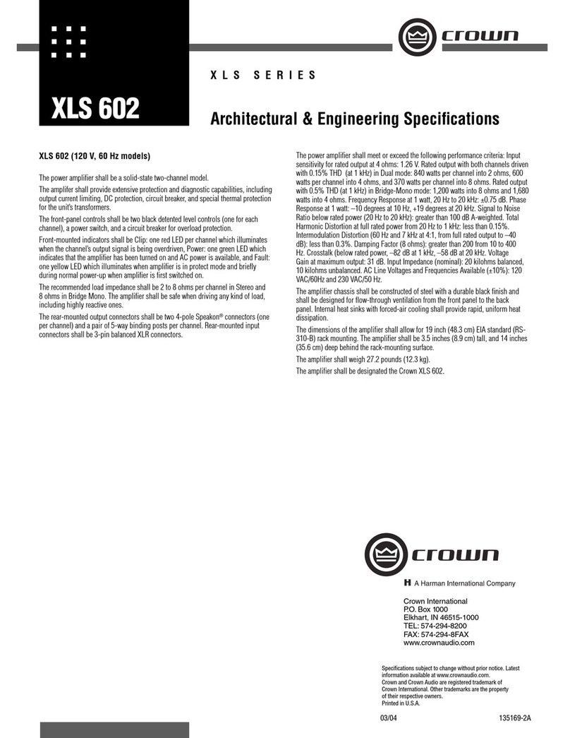
MA-24x6
MACRO-TECH SERIES
The Crown Macro-Tech Series is the defin-
ing standard for amplifier design today.
No compromises, no gimmicks. Just bril-
liant engineering backed by superior manufac-
turing, support and an unsurpassed commit-
ment to quality. Like all Crown amps, the defin-
ing characteristic of the Macro-Tech Series is
sonic accuracy. A tight, rock-solid low end,
with smooth, detailed highs and a well-defined
midrange. In short, the most accurate repro-
duction of an audio signal you’ve ever heard.
And because we put the quality of sound above
all else, a Crown is the most coveted amplifier
in the business.
When it comes to manufacturing amps, our
work is based on one simple fact: there are no
shortcuts to quality. And our Macro-Techs have
proven it time and time again in some of the
most demanding applications in the world.
Developing innovative products that meet your
specific needs is what we’re about. Our Macro-
Tech 24x6 and 36x12 provide a practical solu-
tion to biamplified system applications such as
stage moniors. Each amp combines a high-
and medium-power module in a single, low-
profile unit.
For more details about the Crown Macro-Tech
Series, contact the Crown Technical Support
Group at 800-342-6939 or 219-294-8200.
Also, visit the Crown Audio website at
www.crownaudio.com.
Specifications
Note: Specifications relate to 120-volt, 60-Hz units in Stereo
mode with 8-ohm loads and an input sensitivity of 26-dB gain
at 1 kHz rated power unless otherwise specified. Specifica-
tions for units supplied outside the U.S.A. may vary slightly at
different AC voltages and frequencies.
Power
Output Power:
Load Impedance: Safe with all types of loads,
even reactive ones. Rated for 2 to 16 ohms.
Voltage Gain to 8-ohm load at rated output at
1 kHz, maximum level setting:
Channel 1 (2400): 83:1 ±6% or 38 dB ±0.5
dB at 0.775-volt sensitivity; 46:1 ±6% or 33 dB
±0.5 dB at 1.4-volt sensitivity.
Channel 2 (600): 54:1 ±6% or 35 dB ±0.5 dB
at 0.775-volt sensitivity; 30:1 ±6% or 30 dB
±0.5 dB at 1.4-volt sensitivity.
20:1 ±6% or 26 dB ±0.5 dB at +26 dB sensitiv-
ity.
Required AC Mains: All units require 90 watts
or less at idle. Current, voltage and frequency
requirements are provided on the unit’s back
panel.
AC Line Connector: NEMA 5-15P.
Performance
Frequency Response: ±0.1 dB from 20 Hz to
20 kHz at 1 watt.
Phase Response: ±10 degrees from 10 Hz to
20 kHz at 1 watt.
Signal-to-Noise Ratio, 20 Hz to 20 kHz:
Better than 105 dB A-weighted or 100 dB
unweighted below rated full bandwidth power.
Total Harmonic Distortion (THD): At full band-
width power, less than 0.05% from 20 Hz to
1 kHz increasing linearly to less than 0.1% at
20 kHz.
Intermodulation Distortion (IMD): (60 Hz and
7 kHz at 4:1) Less than 0.05% from 10 mil-
liwatts to full bandwidth power.
Damping Factor: Greater than 1,000 from 10
Hz to 400 Hz.
Slew Rate: (Slew rates are limited to useful
levels for ultrasonic/RF protection.) Channel 1,
greater than 30 volts per microsecond; Channel
2, greater than 13 volts per microsecond.
Controls
Enable: A front-panel push button used to turn
the amplifier on and off.
Level: A front-panel 31-detent rotary control
for each channel used to control the output
level.
Sensitivity: A three-position switch inside the
PIP™ compartment used to select the input
sensitivity for both channels: 0.775 volts or 1.4
volts for standard 1 kHz power, or a 26 dB
voltage gain.
Reset: A back-panel push button for each chan-
nel used to reset the circuit breaker that pro-
tects each power supply.
Indicators
Enable: An amber front-panel indicator that
shows the on/off status of the low-voltage
power supply.
Signal/IOC: A green front-panel indicator for
each channel that flashes to show amplifier
output. If a channel’s output waveform differs
from its input by 0.05% or more, the indicator
flashes brightly to show distortion. This func-
tion provides proof of distortion-free perfor-
mance.
ODEP: Each channel has an amber front panel
indicator that shows thermal-dynamic energy
reserve. Normally, each ODEP indicator is lit
to show available reserve energy. The indicator
will dim proportionally as the energy reserve
for its channel descreases. In the rare event
Features
• Crown’s Grounded Bridge™ design delivers
large voltage swings without using easily
stressed output-transistor configurations
like conventional amplifiers. The results are
lower distortion and superior reliability.
• Patented ODEP®(Output Device Emulation
Protection) circuitry compensates for over-
heating and overload to keep the amplifier
working when others would fail.
• IOC®(Input/Output Comparator) circuitry
immediately alerts of any distortion exceed-
ing 0.05%, providing dynamic proof of
distortion-free performance.
• PIP™ (Programmable Input Processor) con-
nector accepts accessory modules that tailor
the amplifier to suit specific applications.
• Convenient high- and medium-power channel
design for biamplified systems such as stage
monitors.
• Very low harmonic and intermodulation
distortion results in the best dynamic transfer
function in the industry.
• Balanced 1/4-inch(6.35-mm) phone jack
inputs for each channel, with balanced XLR
connectors on the standard PIP-FX module.
• Full protection from shorted, open and mis-
matched loads; general overheating; DC;
high-frequency overloads; and internal fault
conditions.
• Three Year, No-Fault, Fully-Transferable
Warranty completely protects your investment
and guarantees its specifications.
LEVEL LEVEL
ON
OFF
30
27
24
21
18
15
12
9
6
3
0ENABLE
ODEP
30
27
24
21
9
6
3
0
SIGNAL/IOC
18
15
12
CH1 CH2
(2400)(
600)
Crown International
P.O. Box 1000
Elkhart, IN 46515-1000
TEL: 574-294-8200
FAX: 574-294-8FAX
www.crownaudio.com
11/01 134167-1
Crown’s Three-Year, No-Fault, Fully-Transferable Warranty
Crown offers a Three-Year, No-Fault, Fully-Transferable Warranty for every new Crown ampli-
fier—an unsurpassed industry standard. With this unprecedented No-Fault protection, your new
Crown amplifier is warranted to meet or exceed original specifications for the first three years of
ownership. During this time, if your amplifier fails, or does not perform to original specifications,
it will be repaired or replaced at our expense. About the only things not covered by this warranty
are those losses normally covered by insurance and those caused by intentional abuse. And the
coverage is transferable, should you sell your amplifier.
See your authorized Crown dealer for full warranty disclosure and details. For customers outside
of the USA, please contact your authorized Crown distributor for warranty information or call
219-294-8200.
MA-24x6
that a channel has no reserve, its indicator will
turn off and the ODEP circuitry will limit the
channel’s output drive.
Input/Output
Input Connector: Two balanced ¼-inch
(6.35-mm) phone jacks on the back panel and
two balanced three-pin female XLR connectors
on the factory-installed PIP-FX.
Input Impedance: Nominally 20 k ohms, bal-
anced. Nominally 10 k ohms, unbalanced.
Maximum Input Level: 13 volts peak.
Input Sensitivity (for rated power at 1 kHz):
0.775 volt, 1.4 volts, or a 26 dB voltage gain.
Output Connectors: Two sets of color-coded
5-way binding posts (for banana plugs, spade
lugs or bare wire).
Output Impedance: Less than 10 milliohms in
series with less than 2 microhenries.
DC Output Offset: (Shorted input) ±10 milli-
volts.
Output Signal: Unbalanced, two-channel.
Protection
Macro-Tech amplifiers are protected against
shorted, open or mismatched loads; overloaded
power supplies; excessive temperature; chain
destruction phenomena; input overload
damage; and high-frequency blowups. They
also protect loudspeakers from input/output DC
and turn-on/turn-off transients.
If unreasonable operating conditions occur, the
patented ODEP circuitry will proportionally limit
the drive level to protect the output transistor
stages, particularly in the case of elevated tem-
perature. Transformer overheating will result in
a temporary shutdown of the affected channel;
when it has cooled to a safe temperature, the
transformer will automatically reset itself. Con-
trolled slew-rate voltage amplifiers prevent RF
burnouts, and input overload protection is pro-
vided by current-limiting resistance at the input.
Turn On: Four-second delay with no dangerous
transients. Delay time can be changed (contact
Crown’s Technical Support Group).
Accessories
Crown PIP modules including IQ-PIP modules.
With the IQ-PIP-USP2 Adapter installed into the
MA-24x6, the amplifier can accept the IQ-PIP-
USP2 module.
Construction
Steel chassis with durable black finish, alumi-
num front panel with Lexan overlay, and spe-
cially designed flow-through ventilation from
front to side panels.
Cooling: Internal heat sinks with forced-air
cooling for rapid, uniform heat dissipation.
Dimensions: EIA Standard 19-inch (48.3-cm)
rack mount width (EIA RS-310-B), 3.5-inch
(8.9-cm) height, 16-inch (40.6-cm) depth
behind the mounting surface and 2.5-inch
(6.3-cm) protrusion in front of the mounting
surface.
Center of Gravity: Approximately 6 inches
(15.2 cm) behind front mounting surface.
Shipping Weight: 54 lbs, 11oz (24.8 kg).
Specifications subject to change without prior notice. Latest infor-
mation available at www.crownaudio.com.
PIP is a trademark, and Crown, IOC, Macro-Tech and
ODEP are registered trademarks of Crown International. Other
trademarks are the property of their respective owners.
Printed in U.S.A.
© 2001 Crown Audio, Inc.
fiINTERNATIONAL, INC.
ELECTRONIC EQUIPMENT
ELKHART, IN 46517
MADE IN U.S.A.
SERIAL NUMBER
0000
000000
UNBALANCED
INPUT WIRING
BALANCED
INPUT WIRING
REG. U.S. PAT. OFF.
3,808,545
4,330,809
4,611,180
THIS AMPLIFIER IS EQUIPPED WITH SELECTABLE INPUT SENSITIVITY. REMOVE P.I.P. MODULE TO ACCESS SENSITIVITY SWITCH.
CH-2
(600)
CH-1
(2400)
CH-2 CH-1
+TIP
RING
SLEEVE
GND
INPUT GROUND LIFT
LIFT
+TIP
SLEEVE
GND
(AFFECTS PHONE INPUTS ONLY.)
INPUTS
MODEL: MACRO-TECH 24x6 SERIES
AC VOLTS: 120 AMPS: 13 60 Hz
(2400)
CLASS 1
OUTPUT
WIRING
REQUIRED.
PUSH TO RESET
(600)
OUTPUTS
CAUTION: TO PREVENT ELECTRIC SHOCK DO NOT REMOVE TOP OR
BOTTOM COVERS. NO USER SERVICEABLE PARTS INSIDE. REFER SER-
VICING TO QUALIFIED SERVICE PERSONNEL. DISCONNECT POWER CORD
BEFORE REMOVING REAR P.I.P. MODULE TO ACCESS GAIN SWITCH.
ATTENTION: D BRANCHER AVANT D’OUVRIR.
WARNING: TO REDUCE THE RISK OF FIRE OR ELECTRIC SHOCK DO
NOT EXPOSE THIS EQUIPMENT TO RAIN OR MOISTURE.
Programmable
Input Processor (P.I.P.)
3
12
GND
INPUT INPUT
CH-2 CH-1
PUSHPUSH
FX

Other manuals for Macro-Tech MA-24X6

2

Other Crown Amplifier manuals

Crown I-Tech 4x3500 HD User manual

Crown

Crown I-Tech 4x3500 HD User manual

Crown Macro-Tech MA-2402 User manual

Crown

Crown Macro-Tech MA-2402 User manual

Crown CDi 6000 User manual

Crown

Crown CDi 6000 User manual

Crown ComTech DriveCore CT 4150 User manual

Crown

Crown ComTech DriveCore CT 4150 User manual

Crown CH1 User manual

Crown

Crown CH1 User manual

Crown Macro-Tech 5002 VZ User manual

Crown

Crown Macro-Tech 5002 VZ User manual

Crown CTs 1200 User manual

Crown

Crown CTs 1200 User manual

Crown CTs 8200 USP/CN User manual

Crown

Crown CTs 8200 USP/CN User manual

Crown CDi 1000 User manual

Crown

Crown CDi 1000 User manual

Crown XLS 2000 User manual

Crown

Crown XLS 2000 User manual

Crown XLS 3U Series Manual

Crown

Crown XLS 3U Series Manual

Crown COMMERCIAL AUDIO 160MA User manual

Crown

Crown COMMERCIAL AUDIO 160MA User manual

Crown CTs 4200 USP/CN User manual

Crown

Crown CTs 4200 USP/CN User manual

Crown Com-Tech CT-400 Quick start guide

Crown

Crown Com-Tech CT-400 Quick start guide

Crown 800 CSL User manual

Crown

Crown 800 CSL User manual

Crown D-150 User manual

Crown

Crown D-150 User manual

Crown Com-Tech CT-1600 User manual

Crown

Crown Com-Tech CT-1600 User manual

Crown CTs 1200 User manual

Crown

Crown CTs 1200 User manual

Crown I-Tech I-T6000 Manual

Crown

Crown I-Tech I-T6000 Manual

Crown Macro-Tech MA-600 User manual

Crown

Crown Macro-Tech MA-600 User manual

Crown CE 2000TX User manual

Crown

Crown CE 2000TX User manual

Crown I-Tech I-T5000 HD User manual

Crown

Crown I-Tech I-T5000 HD User manual

Crown CTS SERIES CTS 3000 User manual

Crown

Crown CTS SERIES CTS 3000 User manual

Crown CDi 2000 User manual

Crown

Crown CDi 2000 User manual

Popular Amplifier manuals by other brands

zapco Z-150.4 II owner's manual

zapco

zapco Z-150.4 II owner's manual

McIntosh MC601 owner's manual

McIntosh

McIntosh MC601 owner's manual

Phonocar 4 Series installation instructions

Phonocar

Phonocar 4 Series installation instructions

Lab.gruppen FP+ Series FP 10000Q Technical data

Lab.gruppen

Lab.gruppen FP+ Series FP 10000Q Technical data

Ground Zero HYDROGEN GZHA 1.1200DXII owner's manual

Ground Zero

Ground Zero HYDROGEN GZHA 1.1200DXII owner's manual

TRIGA TR-INT50W Product installation document

TRIGA

TRIGA TR-INT50W Product installation document

RS100 PA-4040 instructions

RS100

RS100 PA-4040 instructions

Onkyo R-805TX Service manual

Onkyo

Onkyo R-805TX Service manual

Chord SPM 1050 manual

Chord

Chord SPM 1050 manual

Ross ADA-8503 user manual

Ross

Ross ADA-8503 user manual

YORKVILLE Coliseum CA12 brochure

YORKVILLE

YORKVILLE Coliseum CA12 brochure

Toa 9000M2 Series quick start guide

Toa

Toa 9000M2 Series quick start guide

FAME AG-10AM user manual

FAME

FAME AG-10AM user manual

Yamaha M-4 owner's manual

Yamaha

Yamaha M-4 owner's manual

Inter-m PA-2312 Operation manual

Inter-m

Inter-m PA-2312 Operation manual

Shinybow USA SB-3776 instruction manual

Shinybow USA

Shinybow USA SB-3776 instruction manual

Onkyo TX-SV303Pro Service manual

Onkyo

Onkyo TX-SV303Pro Service manual

MC2 Audio ti series Operator's manual

MC2 Audio

MC2 Audio ti series Operator's manual

manuals.online logo
manuals.online logoBrands
  • About & Mission
  • Contact us
  • Privacy Policy
  • Terms and Conditions

Copyright 2025 Manuals.Online. All Rights Reserved.