Cruisair ZF5 Installation guide

L-2031
Zephyr ZF Kit
Zephyr ZF Kits
Features
DIRECT EXPANSION
The cooling-only Zephyr (ZF) air conditioning unit fits
easily beneath a vee-berth or settee, in the bottom of a
closet or any other out-of-the-way location. The quiet,
efficient squirrel-cage blower can be rotated at installation
for either a vertical or horizontal discharge. Air is carried
through insulated ducting to a discharge grill. An optional
dual duct kit is also available, permitting you to discharge
cool air in two locations.
The Zephyr kit contains the air conditioning unit,
sea-water pump, strainer, thru-hull fittings, hoses, duct,
grills controls and all other components. All you'll need to
make the installation is several hours of time and a few
standard tools.
Like all Cruisair products, the Zephyr air conditioner is
backed by a worldwide network of factory-trained
servicing dealers. Wherever you go, you're never far from
a Cruisair dealer.
• 5,000, 10,000, 12,000 or 16,000 BTU cooling-only air
conditioning unit
• Seawater pump
• Control switch & thermostat
(2-knob switch for ZF-5)
(3-knob switch for ZF-10, ZF12 & ZF-16)
• Seawater accessories, including strainer, thru-hull
fitting, valve, hose, clamps & associated hardware
• Return & discharge air grills & insulated flexible duct
Zephyr Air Conditioning Kit
Chill Out In Style
ZF Specifying Guidelines
Divide the boat into three categories:
1. Below deck cabins with sloping sides and few
portlights, such as a vee-berth
2. Mid-deck cabins with vertical sides and large
windows
3. Above deck cabins with many windows and
exposure to sunlight
Measure the area of each cabin in square feet. If one
end of the compartment is narrower than the other, take
your measurement in the middle for an average. Then
use the table below to determine the proper size air
conditioner.
About R-22
The Zephyr air conditioner is pre-charged at the factory
with R-22 refrigerant gas. Under current federal environ-
mental regulations, R-22 will continue to be available at
least through the year 2020. The R-22 is contained in a
closed loop, which is sealed to prevent any of the gas from
escaping into the environment. It will not be necessary for
you to add or remove refrigerant at installation.
Type of Area in Recommended
Cabin Sq. Ft. Zephyr Unit
Below-Deck Up to 85 ZF-5
85-170 ZF-10
170-210 ZF-12
210-275 ZF-16
Mid-Deck Up to 55 ZF-5
55-110 ZF-10
110-140 ZF-12
140-180 ZF-16
Above-Deck Up to 42 ZF-5
42-84 ZF-10
84-110 ZF-12
110-135 ZF-16
Two & Three Knob Rotary Control Optional Dual Duct Kit
Note: The dual duct kit includes a plenum,
one discharge grill & an additional length of
insulated duct.
Revised: 10-11-02 L-2031
P.O. Box 15299 •Richmond, VA 23227-0699 USA •804-746-1313 •Facsimile: 804-746-7248 •[email protected] •www.tmenviro.com
2000 N. Andrews Ave. Ext. •Pompano Beach, FL 33069-1497 USA •954-973-2477 •Facsimile: 954-979-4414 •[email protected]
Fleets Industrial Estate •26 Willis Way •Poole, Dorset BH15 3SU, England •+44(0)870 3306101 •Facsimile: +44(0)870 3306102 •[email protected]
®Taylor★Made is a registered trademark of Nelson A. Taylor Co., Inc.; the Taylor Made Group logo is a trademark of Taylor Made Group, Inc.; the Cruisair logo is a registered trademark and the Taylor Made Environmental logo
is a trademark of Taylor Made Environmental, Inc.
Model Nominal Height Width Depth Weight Voltage Maximum
Capacity (in/mm) (in/mm) (in/mm) (lb/kg) Frequency Amps
(Btu)
ZF5 11.1/282 39.6/18 115V, 60Hz 29
5,000 16/407 11.6/294
ZF5CK 11.6/294 41.3/18.7 220V/240V, 50Hz 17.7
ZF10 115V, 60Hz 44
10,000 12.9/328 20/508 12.8/326 54/24.5
ZF10CK 220V/240V, 50Hz 22
ZF12 115V, 60Hz 48.3
12,000 12.9/328 20/508 12.8/326 58.5/26.6
ZF12CK 220V/240V, 50Hz 27
ZF16 115V, 60Hz 67
16,000 13.5/343 20/508 13.8/350 62/28.2
ZF16CK 220V/240V, 50Hz 32
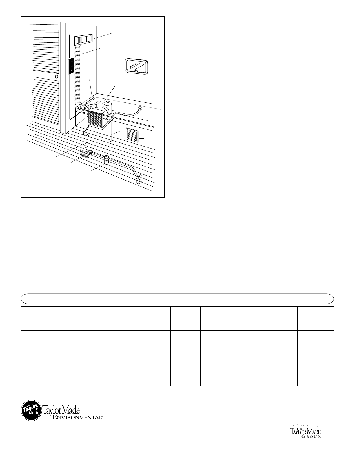
Control Switch
and Thermostat
Insulated
Flex Duct
To AC
Power
Connection
Zephyr Self-Contained
Air Conditioning Unit Overboard
Discharge
Return
Air
Grill
Condensate
Drain
Seawater
Pump
Seawater
Supply
Line
Seawater
Strainer
Thru-hull
Fitting
Valve
Discharge
Grill
ZF Installation Guidelines
The following is a simplified explanation of the steps involved in installing
the Zephyr (ZF) air conditioner. Make sure you refer to the complete
Installation Manual when actually installing the system.
1. Select the Location. The Zephyr unit is normally mounted low in a
closet, under a vee-berth or settee, or any other out-of-the way location.
Cool air is carried through the insulated flexible ducting to a discharge air
grill located on a wall as high as possible in the compartment. Seawater is
pumped through the unit from an underwater thru-hull fitting and is
discharged overboard. The switch assembly is mounted on a convenient
wall in the compartment, no more than 10 ft. from the Zephyr unit. It’s
recommended that the components be placed in the appropriate locations
before starting with the installation, to make sure everything fits.
2. Install the Seawater Plumbing Components. The seawater pump must
be mounted in the bilge below the waterline, and seawater is piped from a
bronze thru-hull fitting through a shut-off valve and strainer to the pump.
From there, water is piped upwards through the Zephyr unit’s condenser,
and then to an overboard discharge fitting above the waterline.
3. Mount the Zephyr Unit. The Zephyr air conditioning unit is mounted on
a flat, horizontal surface, using the metal clips provided. The Zephyr blower
assembly can be rotated for either a horizontal or vertical discharge.
4. Install Grills and Duct. The return air grill should be placed so there is
unobstructed air flow to the Zephyr unit’s evaporator coil. The discharge grill
should be placed as high as possible. A flexible duct is provided to carry air
from the Zephyr unit to the discharge grill. If the dual duct option is required,
a plenum is used to split the air discharge so that air is carried to two
different grills.
5. Connect Electrical Wiring. Cut a hole for the switch assembly. Route
the electrical wiring, along with the copper thermostat capillary tube, to the
Zephyr unit. Mount the thermostat bulb in the return air path. Make wiring
connections using the wiring schematic.
6. Hook Up the Condensate Drains. Attach plastic hose to either or both
of the condensate drain plugs in the pan beneath the unit. Route to an
overboard discharge or sump.
7. Attach Hose Connections. The seawater hoses are secured in place
using double/reversed hose clamps.
TECHNICAL SPECIFICATIONS
This manual suits for next models
15
Other Cruisair Air Conditioner manuals


Popular Air Conditioner manuals by other brands

Fujitsu
Fujitsu ASYG 09 LLCA installation manual

York
York HVHC 07-12DS Installation & owner's manual

Carrier
Carrier Fan Coil 42B Installation, operation and maintenance manual

intensity
intensity IDUFCI60KC-3 installation manual

Frigidaire
Frigidaire FAC064K7A2 Factory parts catalog

Sanyo
Sanyo KS2432 instruction manual


Mitsubishi Electric
Mitsubishi Electric PUHZ-RP50VHA4 Service manual

Panasonic
Panasonic CS-S18HKQ Service manual

Panasonic
Panasonic CS-E15NKE3 operating instructions

Gree
Gree GWH18TC-K3DNA1B/I Service manual

Friedrich
Friedrich ZoneAire Compact P08SA owner's manual

Daikin
Daikin R32 Split Series installation manual