CRUISE CAR VECTOR User manual

CRUISE CAR, INC.
OWNER’S MANUAL
M & R SERIES
VECTOR & SUNRAY MODELS
GAS & ELECTRIC
Cruise Car, Inc. Sarasota Florida 34234 info@cruisecarinc.com Phone: 941-929-1630 Fax: 941-355-6470

1
Cruise Car, Inc.
5120 Middle Ave. Suite 5 —Sarasota, FL 34234
941-929-1630 or [email protected]m
NOTICE
Cruise Car, Inc. is not liable for errors in this manual or for incidental or consequential damages that result from the use of
the material in this manual.
This vehicle conforms to the current American National Standards Institute's Z130 Safety and Performance Requirements for
Golf Cars. This standard, which promotes safety in the design, application, and operation of golf cars, defines a golf car as "a
vehicle used to convey a person or persons and equipment to play the game of golf in an area designated as a golf course."
Throughout this manual, the words "golf car" and "vehicle" are used interchangeably.
The information contained in this document is subject to change without notice.
Cruise Car, Inc. reserves the right to make design changes to vehicles without obligation to make these changes on units
previously sold.

2
FOREWORD
Thank you for choosing Cruise Car, Inc.. Please protect your investment and ensure that your Cruise Car provides years of
reliable, superior performance by reading and following the maintenance instructions in this manual.
Your comfort and safety are important to us as well, so we urge you to read and follow the step-by-step operating
instructions and safety precautions in this manual. These instructions must be followed in order to avoid the risk of severe
personal injury. If you rent or loan your vehicle to others, we recommend that you ask them to read this manual before they
operate the vehicle.
Cruise Car products are backed by a customer support system designed to offer you fast, courteous service. In the event
that your golf car needs repairs or service, please contact Cruise Car, Inc. we will be able to provide technical advice,
perform warranty work, and sell parts and service manuals. For the name and address of the Cruise Car dealer or distributor
nearest you, call 1-941-929-1630.
We hope you will consider this owner's manual a permanent part of your golf car. If you sell the vehicle, please include the
manual so that the next owner will have the important operating, safety, and maintenance information it contains.
REGULAR MAINTENANCE ITEMS
PERIODIC MAINTENANCE ITEMS
Engine Oil Filter (286 cc and 351 cc)
Battery (gasoline vehicle)
Engine Air Filter (286 cc and 351 cc)
Spark Plug O.H.V. (286 cc and 351 cc)
Engine Fuel Filter (286 cc and 351 cc)
Spring Tune-Up Kit
Battery Terminal Protector Spray
Battery, 6 x 8-Volt (electric vehicle)
Dry Moly Lube or Equivalent
Battery, 6 x 8-Volt (heavy-duty electric vehicle
Fuse, 10 Amp, Starting Circuit (gasoline vehicle)
Fuse under Seat near Solenoid
Fuse, 15 Amp, Tow/Run Switch (electric vehicle)
Fuse under Seat beneath Electronics Module Cover
Fuse, 10 Amp, Headlight Circuit (if equipped)
Fuse under Seat beneath Electronics Module Cover
Fuse, 0.5 Amp, Brake Light Circuit (if equipped)
Fuse under Floormat beneath Floor Cover Plate

3
TABLE OF CONTENTS
Safety Decal and Feature Identification......................................................................................................................................... 5
Practice Safety............................................................................................................................................................................... 5
Proposition 65 - State of California................................................................................................................................................ 5
Safety Details................................................................................................................................................................................. 6
General Warnings.......................................................................................................................................................................... 7
Battery Disconnection.................................................................................................................................................................... 9
General Information....................................................................................................................................................................... 10
Model Identification........................................................................................................................................................................ 11
Safety Committee .......................................................................................................................................................................... 11
Controls and Indicators - Electric Vehicles..................................................................................................................................... 12
Controls and Indicators - Gasoline Vehicles.................................................................................................................................. 17
Pre-Operation and Daily Safety Checklist...................................................................................................................................... 20
Performance Inspection................................................................................................................................................................. 21
Driving Instructions ........................................................................................................................................................................ 22
Towing........................................................................................................................................................................................... 25
Transporting on a Trailer................................................................................................................................................................ 26
Storage - Electric Vehicle............................................................................................................................................................... 26
Storage - Gasoline Vehicle............................................................................................................................................................ 27
Maintenance.................................................................................................................................................................................. 30
Periodic Service Schedules........................................................................................................................................................... 31
Periodic Lubrication Schedules...................................................................................................................................................... 35
Vehicle Controller - Electric Vehicles............................................................................................................................................. 37
Batteries - Electric Vehicles........................................................................................................................................................... 37
Battery Charger - Electric Vehicles................................................................................................................................................ 40
Charging Batteries......................................................................................................................................................................... 41
Single Point Watering System (SPWS).......................................................................................................................................... 43

4
Battery - Gasoline Vehicles............................................................................................................................................................ 45
Engine Oil - Gasoline Vehicles ...................................................................................................................................................... 46
Fueling Instructions - Gasoline Vehicles........................................................................................................................................ 49
Cleaning the Vehicle...................................................................................................................................................................... 50
Vehicle Specifications –Electric.................................................................................................................................................... 52
Vehicle Specifications –Gas ......................................................................................................................................................... 53
Corrosion Prevention..................................................................................................................................................................... 54
Solar Top Maintenance.................................................................................................................................................................. 54
Subsequent Owner Registration.................................................................................................................................................... 54

5
Safety signs like you see above may at first seem shocking, but their impact is mild compared with the reality of
severe personal injury.
Your safety and satisfaction are of the utmost importance to us. That is why before operating the vehicle, we
urge you to review the information in this manual. Understand and become familiar with the DANGER,
WARNING, and CAUTION statements and procedures it contains, along with the safety decals that are affixed
to your vehicle.
Take time to understand the language of safety. It is a language that can save your life.
PROPOSITION 65 - STATE OF CALIFORNIA
WARNING
• This product contains or emits chemicals or substances that have been determined by the state of California to
cause cancer and birth defects or other reproductive harm.
PRACTICE SAFETY

6
SAFETY DETAILS
WARNING
•This owner's manual should be read completely before attempting to drive or service the vehicle. Failure to
follow the instructions in this manual could result in property damage, severe personal injury, or death.
It is important to note that some vital statements throughout this manual and on the decals affixed to the vehicle are
preceded by the words DANGER, WARNING, or CAUTION. For your protection, we recommend that you take special notice
of these safety precautions. Safety precautions are essential and must be followed.
Throughout this manual and on the operation and safety decals affixed to the vehicle, the words "golf car" and "vehicle" are
used interchangeably. "Golf car" is defined in the Notice of this manual and no other representation is stated or implied.
If any of the operation or safety decals on the vehicle become damaged, have been removed or cannot be easily read, they
should be replaced immediately to avoid possible property damage, personal injury, or death. Contact your distributor/dealer.
DANGER
•A DANGER indicates an immediate hazard that will result in severe personal injury or death.
WARNING
•A WARNING indicates an immediate hazard that could result in severe personal injury or death.
CAUTION
•A CAUTION with the safety alert symbol indicates a hazard or unsafe practice that could result in minor
personal injury.
CAUTION
•A CAUTION without the safety alert symbol indicates a potentially hazardous situation that could result in
property damage.

7
GENERAL WARNINGS
The following safety statements must be heeded whenever the vehicle is being operated, repaired, or serviced.
Other specific safety statements appear throughout this manual and on the vehicle.
DANGER
DANGER
•Gasoline - Flammable! Explosive! Do not smoke. Keep sparks and flames away from the vehicle and service
area. Service only in a well-ventilated area.
•Do not operate engine in an enclosed area without proper ventilation. The engine produces carbon monoxide,
which is an odorless, deadly poison.
•The vehicle will not provide protection from lightning, flying objects, or other storm-related hazards. If caught
in a storm while driving a Cruise Car vehicle, exit the vehicle and seek shelter in accordance with applicable
safety guidelines for your location.
WARNING
•Follow the procedures exactly as stated in this manual, and heed all DANGER, WARNING, and CAUTION
statements in this manual as well as those on the vehicle and battery charger.
•Do not leave children unattended on vehicle.
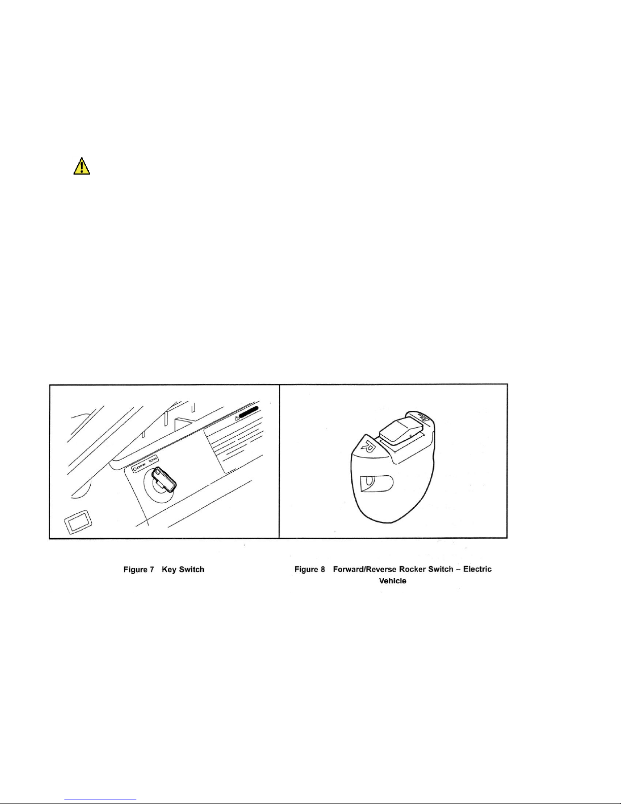
•Prior to leaving the vehicle unattended or servicing the vehicle, set the park brake, place the
Forward/Reverse handle or switch in the NEUTRAL position, turn the key switch to the OFF position, and
remove the key. Chock the wheels when servicing the vehicle.
•Improper use of the vehicle or failure to properly maintain it could result in decreased vehicle performance,
severe personal injury, or death.
•Any modification or change to the vehicle that affects the stability or handling of the vehicle, or increases
maximum vehicle speed beyond factory specifications, could result in severe personal injury or death.
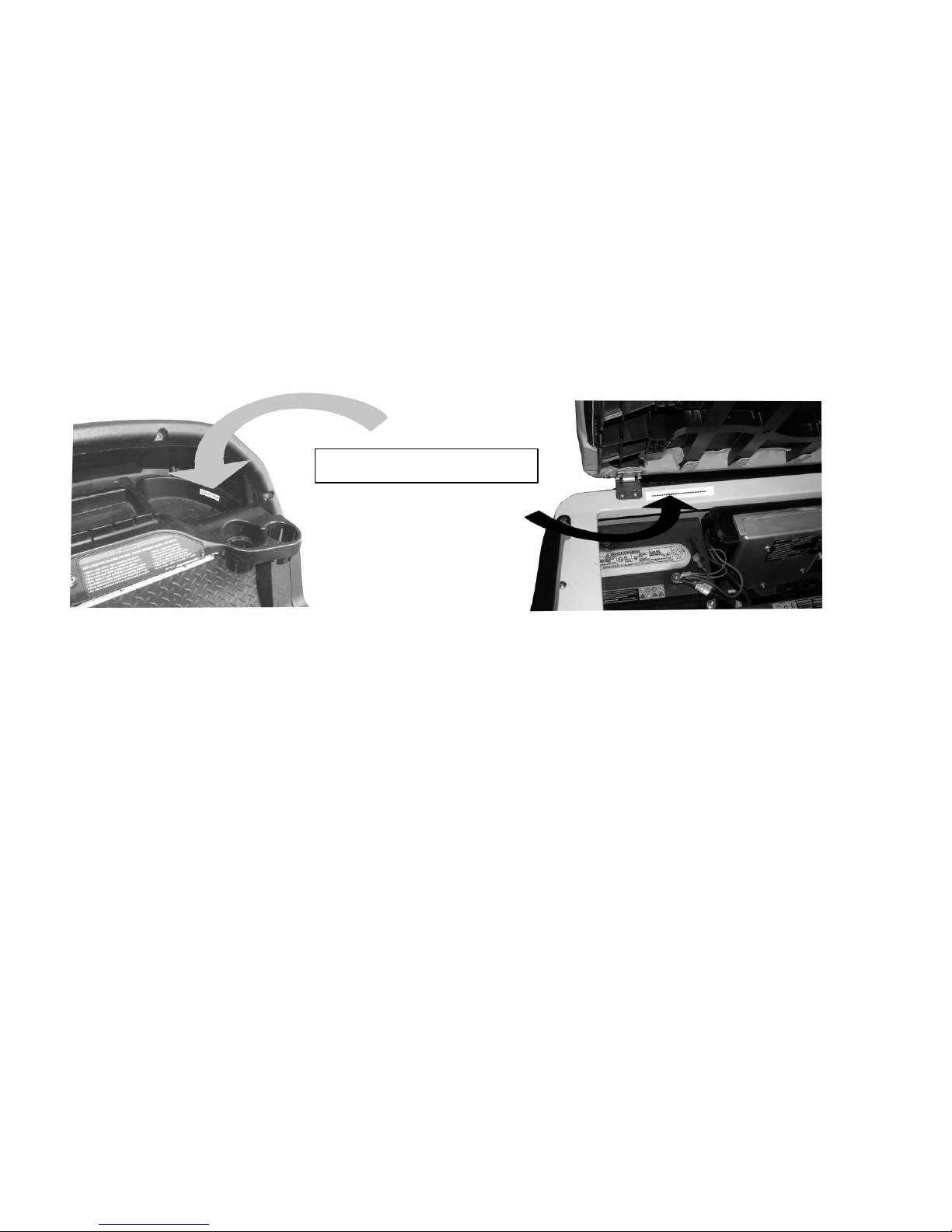
•Check the vehicle for proper location of all vehicle safety and operation decals and make sure they are in
place and are easy to read.
•Only trained technicians should service or repair the vehicle or battery charger. Anyone doing even simple
repairs or service should have knowledge and experience in electrical and mechanical repair. The
appropriate instructions must be used when performing maintenance, service, or accessory installation.
•Wear safety glasses or approved eye protection when servicing the vehicle or battery charger. Wear a full
face shield and rubber gloves when working on or near batteries.
•Do not wear loose clothing or jewelry such as rings, watches, chains, etc., when servicing the vehicle or
battery charger.
•Use insulated tools when working near batteries or electrical connections. Use extreme caution to avoid
shorting of components or wiring.
Electric vehicle only:
• Battery - Explosive gases! Do not smoke. Keep sparks and flames away from the vehicle and service area.
Ventilate when charging or operating vehicle in an enclosed area. Wear a full face shield and rubber gloves
when working on or near batteries.

8
•Place Tow/Run switch in the TOW position before disconnecting or connecting the batteries. Failure to
heed this warning could result in a battery explosion or severe personal injury.
•To avoid unintentionally starting the vehicle, disconnect the batteries as shown. See Battery Disconnection
on page 9.
•After disconnecting the batteries, wait 90 seconds for the controller capacitors to discharge.
Gasoline vehicle only:
•To avoid unintentionally starting the vehicle:
•- Disconnect battery cables, negative (-) cable first (Figures 2,3,4,5).

9
WARNING
•Disconnect the spark plug wire from the spark plug.
• Frame ground - Do not allow tools or other metal objects to contact frame when disconnecting battery
cables or other electrical wiring. Do not allow a positive wire to touch the vehicle frame, engine, or any
other metal component.
BATTERY DISCONNECTION
Refer to the following figures for correct battery disconnection information for your vehicle

10
GENERAL INFORMATION
Cruise Cars are available with either electric or gasoline power. Throughout this manual, important features unique to each
model are highlighted. We urge the owner/operator to read and understand this manual, and to pay special attention to the
features specific to his/her vehicle(s).

11
MODEL IDENTIFICATION
The serial number of your Cruise Car is printed on a label located in front of the passenger foot well above the dash, or
underneath the driver side seat on the edge of the seat pedestal. (Figure 6.1 and 6.2)
NOTE: Have the vehicle serial number available when ordering parts or making inquiries.
SAFETY COMMITTEE
If the cart is to be rented or is part of a fleet, we strongly recommend that a safety committee be appointed. One of the main
concerns of this committee should be the safe operation of the golf cars.
This should include at a minimum:
•Where golf cars should be driven.
•Ensuring that proper warnings of driving hazards are displayed and visible.
•Who should and who should not drive golf cars.
•Instructing first time drivers.
•Maintaining golf cars in a safe driving condition.
•How various rules are to be enforced.
Figure 6.1 –Serial Number Decal
Figure 6.2 –Serial Number Decal
# # # # # # # # # # # # #

12
CONTROLS AND INDICATORS - ELECTRIC VEHICLES
See General Warnings on page 7.
WARNING
•If renting or loaning the vehicle, make sure the driver is familiar with all controls and operating procedures
before allowing the vehicle to be driven.
•Do not shift the Forward/Reverse switch while the vehicle is moving. To avoid injury to an unsuspecting
passenger or damage to the vehicle, always bring the vehicle to a full stop before shifting the
Forward/Reverse switch.
•Release the accelerator pedal and then press the brake pedal firmly until the vehicle stops. To avoid
unintentionally starting or rolling the vehicle, set the park brake, place the Forward/Reverse switch in the
NEUTRAL position, turn the key switch to the OFF position, and remove the key when leaving the vehicle.
KEY SWITCH
The key switch is mounted on the dash to the right of the steering column (Figure 7). It has two positions, OFF and ON,
which are clearly labeled. See following NOTE.
FORWARD/REVERSE CONTROL
The Forward/Reverse rocker switch is located on the seat support panel, below and to the right of the driver's
right knee (Figure 8). The F (FORWARD) and R (REVERSE) are clearly marked. Push down the FORWARD
side of the switch to operate the vehicle in the forward direction, or push down the REVERSE side of the switch
to operate the vehicle in reverse. When the rocker switch is positioned in the NEUTRAL position, with neither
side down, the vehicle will not operate if the accelerator pedal is pressed. The reverse buzzer will sound as a
warning when the Forward/Reverse switch is in the REVERSE position

13
ACCELERATOR PEDAL
The accelerator pedal is the pedal on the right, with the word GO molded into it (Figure 9). The operation of the accelerator
pedal differs from that of an automobile. When the key switch is the ON position, and the Forward/Reverse switch is in either
the FORWARD or REVERSE position, pressing the accelerator pedal will automatically release the park brake and start the
vehicle moving in the direction selected (forward or reverse). As the accelerator pedal is pressed, speed will increase until
full speed is reached. When the accelerator is released, power will be cut off and the motor will stop running.
Electric vehicles use a special electrical system, which employs motor braking in some modes of operation. In those
modes, the vehicle operates as follows:
• Walk Away Braking: This feature prevents the vehicle from rolling away uncontrolled should the driver park on a slope
and leave the vehicle without locking the park brake. The vehicle will roll at about 1 mph (1.6 km/h). If the walk away
braking function remains engaged for two seconds or more, a warning buzzer will sound to alert the driver that motor
braking has been activated. See following WARNING.
WARNING
• Walk away braking will not limit vehicle speed to 1 mph (1.6 km/h) on very steep grades.
Do not operate vehicle on slopes exceeding 20% grades.
Excel System Vehicles
•Motor Braking:This feature helps to control vehicle downhill speed. When traveling downhill, motor braking engages to
maintain speeds proportional to the accelerator pedal position. For example, when the accelerator is fully pressed, motor
braking holds the vehicle at the programmed top speed. When the accelerator pedal is fully released, motor braking slows the
vehicle to a complete stop or allows the vehicle to coast freely, depending upon the selected controller setting. This feature is
selectable. Contact your dealer/distributor to inquire about this feature.
IQ System Vehicles
•Pedal Up Motor Braking: When vehicle speed is above 11 mph (17.7 km/h), releasing the accelerator pedal will activate
motor braking, which slows the vehicle speed. Once vehicle speed slows to below approximately 11 mph (17.7 km/h), with the
accelerator pedal still released, motor braking will be deactivated and the vehicle will coast freely. This feature is selectable.
Contact your dealer/distributor to inquire about this selectable feature.
•Pedal Down Motor Braking: This feature helps to control vehicle downhill speed. Motor braking is activated when the
vehicle reaches the programmed top speed and holds the vehicle at that speed. Motor braking is automatically disengaged
when vehicle speed slows below the programmed top speed.

14
BRAKE PEDAL
The brake pedal is the large pedal on the left with the word STOP molded into it. To slow or stop the vehicle, press the brake
pedal with your foot (Figure 10).
PARK BRAKE PEDAL
The park brake pedal is the small raised portion in the upper left corner of the brake pedal. It has the word PARK molded
into it. To set the park brake, press the brake pedal firmly and tilt the park brake portion of the pedal forward with your foot
(Figure 11). See following WARNING and NOTE.
WARNING
• The park brake will release automatically when either the accelerator or brake pedal is pressed. The park
brake has multiple locking positions and should be firmly pressed and locked to prevent the vehicle from
rolling.
NOTE: Vehicles equipped with lights: After the park brake is engaged, the brake lights will remain illuminated for up to
four minutes.

15
BATTERY WARNING LIGHT
Some electric vehicles are equipped with a dash-mounted warning light (below the steering column) that, when the vehicle is
in operation, indicates low battery voltage or, when the vehicle is being charged, indicate a charging problem (Figure 12).
The battery warning light is controlled by the onboard computer (if so equipped).
When the vehicle is in operation, the warning light is controlled by the onboard computer (if so equipped).
•Batteries' voltage drops below 48 volts when there is no load on the batteries (the vehicle is stopped and there are no
accessories on).
•Batteries have discharged to less than 25% of rated capacity.
If the warning light illuminates when the vehicle is operating, there will be enough power remaining to drive the vehicle for
approximately 30 minutes. However, the vehicle should be charged at the first opportunity. If the warning light illuminates
and the vehicle is unable to operate for 30 minutes, have your cart checked for a possible battery or electrical system
problem.
When the batteries receive an incomplete charge because 1) the DC power cord is disconnected, 2) AC power to the
charger is interrupted, 3) automatic charger shut-off occurs after 16 hours of operation, 4) the charger malfunctions, or 5) the
wrong charger is used, the warning light will indicate as follows:
•The warning light will not illuminate if the charge is 90% or more complete. The onboard computer (if equipped) will retain
in memory the amount of charge needed to fully replenish the batteries and will complete the charge during the next
charge cycle.
•When the charger is unplugged, the warning light will illuminate and remain illuminated for 10 seconds if the charge is less
than 90% complete but the vehicle has enough power for approximately 30 minutes of operation. This will alert the
operator that the vehicle may be used, but that it must be charged to completion as soon as possible.
•The warning light will repeatedly illuminate for 10 seconds, with 4 second intervals if the charger times out at 1.6 hours and
the batteries are not sufficiently charged. This indicates an abnormal charge cycle. The charger and batteries should be
checked.
•The warning light will repeatedly illuminate for 10 seconds, with 4 second intervals during a charge cycle (DC plug is still
connected) if AC power to the charger is interrupted. The light will go out when AC power is restored.

16
TOW/RUN SWITCH
WARNING
•Place Tow/Run switch in the TOW position before disconnecting or connecting the batteries. Failure to
heed this warning could result in a battery explosion or severe personal injury.
•When the Tow/Run switch is in the TOW position, all motor braking functions, including walk away braking,
are disabled.
Electric vehicles are equipped with a Tow/Run switch, located under the seat between the batteries (Figure 13) or (Figure
14). The switch must be in the RUN position in order to operate the vehicle. When the switch is in the TOW position, power
to the vehicle electrical components is turned off and the vehicle will not operate. See following NOTE.
NOTE: After placing the Tow/Run switch in the TOW position, allow 10 seconds to elapse before switching back to the
RUN position.
After placing the Tow/Run switch in the RUN position, allow 10 seconds to elapse before operating the vehicle.
The Tow/Run switch should be placed in the TOW position under the following conditions:
•Before Towing the Vehicle: Place the Tow/Run switch in the TOW position to disable all motor braking functions, thus
preventing possible damage that could occur to the vehicle or electrical components if the vehicle is towed while the walk
away braking motor braking function is operating.
•Before Disconnecting or Connecting Battery Cables: Place the Tow/Run switch in the TOW position to turn off power
to the vehicle electrical system, thus preventing severe arcing and possible battery explosion as the battery cables are
disconnected.
•For Long Term Storage: Place the Tow/Run switch in the TOW position to turn off power to the vehicle electrical system,
thus preventing vehicle electrical components from discharging the batteries.

17
CONTROLS AND INDICATORS - GASOLINE VEHICLES
See General Warnings on page 7.
WARNING
•If renting or loaning the vehicle, make sure the driver is familiar with all controls and operating procedures
before allowing the vehicle to be driven.
•Do not shift the Forward/Reverse handle while the vehicle is moving. To avoid injury to an unsuspecting
passenger or damage to the vehicle, always bring the vehicle to a full stop before shifting the
Forward/Reverse handle.
•Release the accelerator pedal and then press the brake pedal firmly until the vehicle stops. To avoid
unintentionally starting or rolling the vehicle, set the park brake, place the Forward/Reverse handle in the
NEUTRAL position, turn the key switch to the OFF position, and remove the key.
•Do not tamper with the governor. Doing so will void the warranty, as well as damage the engine and other
components, and could result in property damage, personal injury, or death due to unsafe speed.
KEY SWITCH
The key switch is mounted on the dash to the right of the steering column (Figure 15). It has two positions, OFF and ON,
which are clearly labeled. See following NOTE.
NOTE: The key can be removed only when the key switch is in the OFF position.
FORWARD/REVERSE CONTROL
The Forward/Reverse handle is located on the seat support panel, below and to the right of the driver's right knee (Figure
16). The handle has three distinct positions: F (FORWARD), N (NEUTRAL), and R (REVERSE). Rotate the handle towards
the driver (FORWARD) to operate the vehicle in the forward direction, or towards the passenger (REVERSE) to operate the
vehicle in reverse. When the handle is in the straight up position, (NEUTRAL), the vehicle will not operate. The engine will
stop if it is shifted to this position during operation. Our vehicles operate at reduced speed in reverse. The reverse buzzer will
sound as a warning when the Forward/Reverse handle is in the REVERSE position.

18
ACCELERATOR PEDAL
The accelerator pedal is the pedal on the right, with the word GO
molded into it (Figure 17). The operation of the accelerator pedal
differs from that of an automobile. When the key switch is in the ON
position, and the Forward/Reverse handle is in either the
FORWARD or REVERSE position, pressing the accelerator pedal
will automatically release the park brake and start the vehicle
moving in the direction selected (forward or reverse). As the
accelerator pedal is pressed, speed will increase until full speed is
reached. When the accelerator is released, power will be cut off and
the motor will stop running
BRAKE PEDAL
The brake pedal is the large pedal on the left with the word STOP molded into it. To slow or stop the vehicle, press the brake
pedal with your foot (Figure 18).
PARK BRAKE PEDAL
The park brake pedal is the small raised portion in the upper left corner of the brake pedal. It has the word PARK molded into
it. To set the park brake, press the brake pedal firmly and tilt the park brake portion of the pedal forward with your foot
(Figure 19). See following WARNING and NOTE.

19
WARNING
•The park brake will release automatically when either the accelerator or brake pedal is pressed. The park
brake has multiple locking positions and should be firmly pressed and locked to prevent the vehicle from
rolling.
NOTE: Vehicles equipped with lights: After the park brake is engaged, the brake lights will remain illuminated for up to
four minutes.
NEUTRAL LOCKOUT
For the convenience of the trained technician, there is a neutral lockout cam located on the back of the Forward/Reverse
shifter. If the neutral lockout cam is pulled out approximately 3/8 inch (10 mm) and then rotated one-half turn until it snaps
into place, the cam will be in the MAINTENANCE position (Figure 20). This will allow the technician to operate the engine in
neutral for certain maintenance procedures. With the cam in this position, the vehicle will not operate if the Forward/Reverse
handle is placed in either the FORWARD or REVERSE position.
To put the cam back into the OPERATE position, pull the cam out approximately 3/8 inch (10 mm) and rotate it one-half turn
until it snaps into place (Figure 21). See following WARNING and NOTE.
WARNING
•With the cam in the MAINTENANCE position and the engine running, the vehicle may move suddenly if the
Forward/Reverse handle is shifted or accidentally bumped. To prevent this, chock the front and rear wheels and
firmly set the park brake before servicing or leaving the vehicle.
NOTE: Be sure to return the cam to the OPERATE position after servicing the vehicle, or it will not operate with the
Forward/Reverse handle in either the FORWARD or REVERSE position.
This manual suits for next models
1
Table of contents
Popular Golf Car manuals by other brands

Columbia ParCar
Columbia ParCar P4G Service manual

Ingersoll-Rand
Ingersoll-Rand Club Car VILLAGER 8 ELECTRIC Operator's manual

Power Wheels
Power Wheels Barbie owner's manual

Club Car
Club Car 1998 DS Maintenance service manual

WindRunner
WindRunner G1 user manual

Columbia
Columbia EAGLE P4 Owner's and operator's manual