Textron EZGO TXT FLEET Guide

Service Parts Manual
ELECTRIC POWERED VEHICLE
634464-BE
ISSUED AUGUST 2013 REVISED SEPTEMBER 2019


Page i
Service Parts Manual
SERVICE PARTS MANUAL
48V ELECTRIC POWERED GOLF CARS
TXT FLEET
TXT FREEDOM
TXT SHUTTLE 2+2
STARTING MODEL YEAR 2014
DISCLAIMER: The E-Z-GO Division of Textron Inc. (E-Z-GO) reserves the right to incorporate engineering and design changes to products in this Manual,
without obligation to include these changes on units leased/sold previously.
The information contained in this Manual may be revised periodically E-Z-GO, and therefore is subject to change without notice.
E-Z-GO DISCLAIMS LIABLITY FOR ERRORS IN THIS MANUAL, and E-Z-GO SPECIFICALLY DISCLAIMS LIABILITY FOR INCIDENTAL AND CONSE-
QUENTIAL DAMAGES RESULTING FROM THE USE OF THE INFORMATION AND MATERIALS IN THIS MANUAL.
TO CONTACT US
NORTH AMERICA:
TECHNICAL ASSISTANCE & WARRANTY PHONE: 1-800-774-3946, FAX: 1-800-448-8124
SERVICE PARTS PHONE: 1-888-GET-EZGO (1-888-438-3946), FAX: 1-800-752-6175
INTERNATIONAL: PHONE: 001-706-798-4311, FAX: 001-706-771-4609
E-Z-GO DIVISION OF TEXTRON INC., 1451 MARVIN GRIFFIN RD., AUGUSTA, GEORGIA USA 30906-3852

Page ii Service Parts Manual
GENERAL INFORMATION
To obtain a copy of the limited warranty applicable to the vehicle, call or write a local
Distributor, authorized Branch or the Warranty Department with vehicle serial number and
manufacturer code.
The use of non Original Equipment Manufacturer (OEM) parts may void the warranty.
Overfilling of batteries may void the warranty.
BATTERY PROLONGED STORAGE
All batteries will self discharge over time. The rate of self discharge varies depending on the
ambient temperature and the age and condition of the batteries.
A fully charged battery will not freeze in winter temperatures unless the temperature falls
below -75° F (-60° C).
As with all electric vehicles, the batteries must be checked and recharged as required or at
a minimum of 30 day intervals.
BATTERY DISPOSAL
Lead-acid batteries are recyclable. Return whole scrap batteries to distributor,
manufacturer or lead smelter for recycling. For neutralized spills, place residue in acid-
resistant containers with absorbent material, sand or earth and dispose of in accordance
with local, state and federal regulations for acid and lead compounds. Contact local and/or
state environmental officials regarding disposal information.

Page iii
TABLE OF CONTENTS
Service Parts Manual
SECTION Page No.
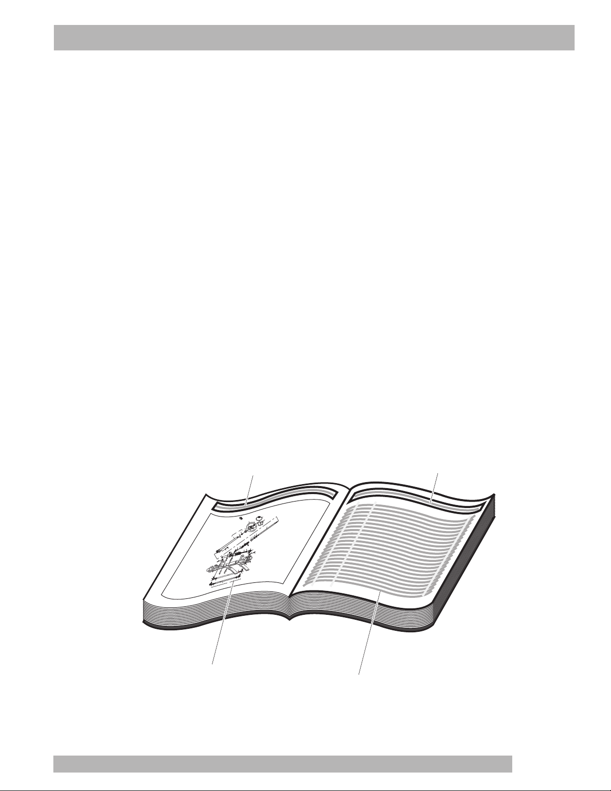
HOW TO USE THE SERVICE PARTS MANUAL. . . . . . . . . . . . . . . . . . . . . . . . . . . . . . . . . . . . . . . . . . . . . . . v
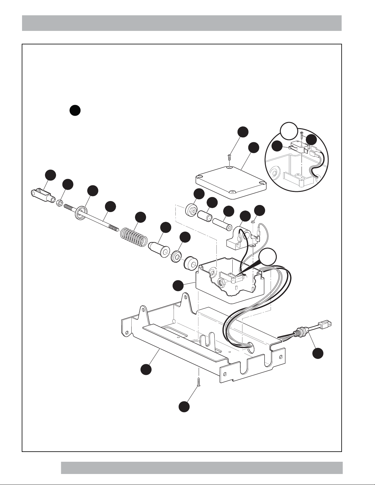
ACCELERATOR . . . . . . . . . . . . . . . . . . . . . . . . . . . . . . . . . . . . . . . . . . . . . . . . . . . . . . . . . . . . . . . . . . . . . . . . A
BATTERY CHARGER. . . . . . . . . . . . . . . . . . . . . . . . . . . . . . . . . . . . . . . . . . . . . . . . . . . . . . . . . . . . . . . . . . . . .B
BODY. . . . . . . . . . . . . . . . . . . . . . . . . . . . . . . . . . . . . . . . . . . . . . . . . . . . . . . . . . . . . . . . . . . . . . . . . . . . . . . . . C
BODY - FRONT. . . . . . . . . . . . . . . . . . . . . . . . . . . . . . . . . . . . . . . . . . . . . . . . . . . . . . . . . . . . . . . . . . C - 1
BODY - MID SECTION . . . . . . . . . . . . . . . . . . . . . . . . . . . . . . . . . . . . . . . . . . . . . . . . . . . . . . . . . . . . C - 5
BODY - REAR. . . . . . . . . . . . . . . . . . . . . . . . . . . . . . . . . . . . . . . . . . . . . . . . . . . . . . . . . . . . . . . . . . . C - 7
BODY - ACCESSORIES. . . . . . . . . . . . . . . . . . . . . . . . . . . . . . . . . . . . . . . . . . . . . . . . . . . . . . . . . . C - 11
BRAKES . . . . . . . . . . . . . . . . . . . . . . . . . . . . . . . . . . . . . . . . . . . . . . . . . . . . . . . . . . . . . . . . . . . . . . . . . . . . . . .D
ELECTRICAL . . . . . . . . . . . . . . . . . . . . . . . . . . . . . . . . . . . . . . . . . . . . . . . . . . . . . . . . . . . . . . . . . . . . . . . . . . .E
ELECTRONIC SPEED CONTROL . . . . . . . . . . . . . . . . . . . . . . . . . . . . . . . . . . . . . . . . . . . . . . . . . . . . . . . . . . .F
FRONT SUSPENSION AND STEERING . . . . . . . . . . . . . . . . . . . . . . . . . . . . . . . . . . . . . . . . . . . . . . . . . . . . . G
MOTOR . . . . . . . . . . . . . . . . . . . . . . . . . . . . . . . . . . . . . . . . . . . . . . . . . . . . . . . . . . . . . . . . . . . . . . . . . . . . . . . .H
REAR AXLE . . . . . . . . . . . . . . . . . . . . . . . . . . . . . . . . . . . . . . . . . . . . . . . . . . . . . . . . . . . . . . . . . . . . . . . . . . . J
REAR SUSPENSION . . . . . . . . . . . . . . . . . . . . . . . . . . . . . . . . . . . . . . . . . . . . . . . . . . . . . . . . . . . . . . . . . . . . K
SEATING. . . . . . . . . . . . . . . . . . . . . . . . . . . . . . . . . . . . . . . . . . . . . . . . . . . . . . . . . . . . . . . . . . . . . . . . . . . . . . .L
SEATING - CONVERTIBLE CARRIER . . . . . . . . . . . . . . . . . . . . . . . . . . . . . . . . . . . . . . . . . . . . . . . L - 1
SEATING AND BAG HOLDER - GOLF CAR. . . . . . . . . . . . . . . . . . . . . . . . . . . . . . . . . . . . . . . . . . L - 11
TOW BAR . . . . . . . . . . . . . . . . . . . . . . . . . . . . . . . . . . . . . . . . . . . . . . . . . . . . . . . . . . . . . . . . . . . . . . . . . . . . . M
PERMANENT . . . . . . . . . . . . . . . . . . . . . . . . . . . . . . . . . . . . . . . . . . . . . . . . . . . . . . . . . . . . . . . . . . .M - 1
CASUAL . . . . . . . . . . . . . . . . . . . . . . . . . . . . . . . . . . . . . . . . . . . . . . . . . . . . . . . . . . . . . . . . . . . . . . .M - 5
WEATHER PROTECTION . . . . . . . . . . . . . . . . . . . . . . . . . . . . . . . . . . . . . . . . . . . . . . . . . . . . . . . . . . . . . . . . N
WHEELS AND TIRES . . . . . . . . . . . . . . . . . . . . . . . . . . . . . . . . . . . . . . . . . . . . . . . . . . . . . . . . . . . . . . . . . . . . P

Page iv
NOTES
Service Parts Manual

Page v
Service Parts Manual
This manual is divided into several sections:
•GENERAL INFORMATION
•ILLUSTRATED PARTS BREAKDOWN
•APPENDIX
The first section, GENERAL INFORMATION, contains the following information:
•WARRANTY INFORMATION
•GENERAL INDEX
•HOW TO USE THE SERVICE PARTS MANUAL
The second section, ILLUSTRATED PARTS BREAKDOWN, contains illustrations and parts lists for all systems of your
vehicle.
The third section, APPENDIX, contains a listing of specialty products and accessories.
USE OF THE MANUAL
To use this manual, consult the GENERAL INDEX to locate the information or illustration required.
Introduction of some revisions varies due to supply of components; therefore, it is possible that various combinations of
components may be found that are not directly reflected by each illustration. Consult the illustration that best suits your
situation and then contact the Service Parts Department. It is important that the serial number of your vehicle and its
model number be supplied to Service Parts when ordering any replacement components.
Locate the serial number plate (see BODY located in the Illustrated Parts Breakdown section of this manual for its loca-
tion) and note the complete number shown on the plate.
Title Title
Left hand illustration page
(continued on right hand page
if required)
Parts list (continued on
rear of page if required)
Front of Vehicle
123
101
100
99
98
120
74
70
71
64
63
65
66
67
121
122
114
119
115
111
73
72
112
118
116
113
62
69
94
96
95
82,87
81,86
84,89
83,88
102,104
105
79
91
92
107
106
62 - IncludesItems 63 - 66, 69 - 74
70 - Includes Items 71 - 74
81 - Includes Items 82 - 84
86 - Includes Items87 - 89
94 - IncludesItems 95, 96
111- Includes Items 112- 114
118- Includes Items119- 121
126 - IncludesItems 127 - 131
103
*See Body Section for
decal information
127
128129
130
131
126
HOW TO USE THE SERVICE PARTS MANUAL

Page vi Service Parts Manual
HOW TO USE THE SERVICE PARTS MANUAL
1. WHEN THE PART NUMBER IS NOT KNOWN
•Determine the function and application of the part required. Turn to the General Index and select the most
appropriate title.
•Turn to the page number indicated and locate the desired part on the illustration.
•From the illustration, obtain the item number assigned to the desired part. Refer to the accompanying
description for specific information regarding the part.
2. IF YOU KNOW THE PART NUMBER
•Locate the part number or description in the appropriate column on the parts list page.
NOTE: It is suggested that you confirm that the part selected is correct by verifying it with the pictorial representation
on the illustrated page.
Should an asterisk (*) appear in the part number column on the parts list page, read upwards until a part number is
found. The part number is the lowest assembly sold by Service Parts and the asterisk (*) indicates that the part
depicted is not available for purchase.
NOTE: Descriptions are indented under the assembly that they are used on. That assembly is, in turn listed under the
assembly that it is used on. This process is repeated until the highest final assembly is reached.
To facilitate the maintenance and repair of the vehicle, a Technician’s Repair and Service Manual is
available from the Service Parts Department.

Page vii
Service Parts Manual
3. COLOR CODE FOR BODY COMPONENTS
The last two digits of the part number for the body part will denote the color code. Locate the part number for the cowl,
rear body, seat pod, side panel or seat wrap then locate your color in the list below. Replace the last ** or XX with the
two digit color code.
CODE # DESCRIPTION CODE # DESCRIPTION
05 JACOBSEN ORANGE 105 JACOBSEN ORANGE (WITH LIGHTS)
11 BLACK 111 BLACK (WITH LIGHTS)
17 LIGHT BEIGE 119 PATRIOT BLUE PEARL (WITH LIGHTS)
18 MUSHROOM 120 INFERNO RED METALLIC (WITH LIGHTS)
19 PATRIOT BLUE PEARL 126 STEEL BLUE PEARL (WITH LIGHTS)
20 INFERNO RED METALLIC 131 METALLIC CHARCOAL (WITH LIGHTS)
26 STEEL BLUE PEARL 135 SAFETY YELLOW (WITH LIGHTS)
31 METALLIC CHARCOAL 136 IVORY (WITH LIGHTS)
35 SAFETY YELLOW 137 FOREST GREEN (WITH LIGHTS)
36 IVORY 138 BRIGHT WHITE (WITH LIGHTS)
37 FOREST GREEN 139 FLAME RED (WITH LIGHTS)
38 BRIGHT WHITE 141 ELECTRIC BLUE (WITH LIGHTS)
39 FLAME RED 142 PLATINUM (WITH LIGHTS)
41 ELECTRIC BLUE 143 BURGUNDY (WITH LIGHTS)
42 PLATINUM 144 ALMOND (WITH LIGHTS)
43 BURGUNDY 151 SUNBURST ORANGE (WITH LIGHTS)
44 ALMOND 152 BRITISH RACING GREEN (WITH LIGHTS)
51 SUNBURST ORANGE 174 BARLEY GOLD (WITH LIGHTS)
52 BRITISH RACING GREEN 175 OASIS GREEN (WITH LIGHTS)
74 BARLEY GOLD 176 JAVA BROWN (WITH LIGHTS)
75 OASIS GREEN
76 JAVA BROWN
A5 OCEAN GRAY
HOW TO USE THE SERVICE PARTS MANUAL

Page A-1 Service Parts Manual
ACCELERATOR
To Harness
from
Direction
Selector
A
A
PEDAL BOX ASSEMBLY includes items 3 - 43
1
13
11
15
3
9
26
20
3
21
28
29
23
5
4
8
7
17
16
14
12

Page A-2
Service Parts Manual
ACCELERATOR
To Harness
from
Direction
Selector
ACCELERATOR PEDAL ASSEMBLY includes items 32 - 35
31
34
35
46
32
41
45
39
38
37
43
37

Page A-3 Service Parts Manual
When ordering parts, please specify the model and serial number of the product.
* Indicates a component that is not available as an individual part.
*** Indicates consult Customer Service Department for additional information.
ITEM PARTNO. 12345 DESCRIPTION QTY.
ACCELERATOR
1 613163 PEDAL BOX ASSEMBLY (INCLUDES ITEMS 3 - 43)..................................... 1
2
3 25853G01 PEDAL BOX AND COVER........................................................................ 1
4 25854G01 INDUCTIVE THROTTLE SENSOR........................................................... 1
5 00983G01 SELF THREADING NUT, 3/16"................................................................. 2
6
7 25857G01 PLUNGER SLEEVE.................................................................................. 1
8 28443G01 PLUNGER................................................................................................. 1
9 28444G01 PLUNGER CAM........................................................................................ 1
10
11 73332G01 ACCELERATOR ROD .............................................................................. 1
12 00532G4 HEX NUT, 5/16" - 24 ................................................................................. 1
13 10385G4 CLEVIS YOKE (ADJUSTABLE)................................................................ 1
14 17677G2 SPRING RETAINER, 3/8"......................................................................... 1
15 73046G01 COMPRESSION SPRING ........................................................................ 1
16 17979G1 ACCELERATOR ROD BUSHING............................................................. 1
17 17677G1 SPRING RETAINER, 1/2"......................................................................... 1
18
19
20 25861G02 MICRO SWITCH....................................................................................... 1
21 01050G01 TORX PAN HEAD PLASTITE SCREW, #4 - 20 X 5/8" LG....................... 2
22
23 620418 WIRING HARNESS (PEDAL BOX ASSEMBLY)....................................... 1
24
25
26 00684G6 PHILLIPS TRUSS HEAD MACHINE SCREW (SS), #8 - 32 X 3/4" LG .... 2
27
28 652241G03 ACCELERATOR PEDAL BRACKET......................................................... 1
29 01051G01 PHILLIPS PAN HEAD SCREW, #8 - 16 X 1/2" LG ................................... 4
30

When ordering parts, please specify the model and serial number of the product.
* Indicates a component that is not available as an individual part.
*** Indicates consult Customer Service Department for additional information.
ITEM PARTNO. 12345 DESCRIPTION QTY.
Page A-4
Service Parts Manual
ACCELERATOR
31 25799G03 ACCELERATOR PEDALASSEMBLY (INCLUDES ITEMS 32 - 35)......... 1
32 652824 ACCELERATOR PEDAL.................................................................... 1
33
34 27512G01 ACCELERATOR PEDAL PAD............................................................ 1
35 16409G1 OVAL RIVET, 3/8" X 15/32" LG.......................................................... 6
36
37 17838G1 NYLON BUSHING.................................................................................... 3
38 74432G01 PEDAL PIVOT PIN, 4.87" LG................................................................... 1
39 12064G6 PUSH NUT, 9/32" I.D................................................................................ 1
40
41 10386G3 CLEVIS PIN, 5/16" X 13/16" LG............................................................... 1
42
43 10387G3 COTTER PIN, 3/32" X 3/4" LG................................................................. 1
44
45 00715G2 HEX HEAD FLANGE BOLT, 5/16" - 18 X .8" LG............................................. 4
46 70135G01 PEDAL PIVOT COVER................................................................................... 1

Page B-1 Service Parts Manual
BATTERY CHARGER
1
2

When ordering parts, please specify the model and serial number of the product.
* Indicates a component that is not available as an individual part.
*** Indicates consult Customer Service Department for additional information.
ITEM PARTNO. 12345 DESCRIPTION QTY.
Page B-2
Service Parts Manual
BATTERY CHARGER
1 635669 48V BATTERY CHARGER, 3 METER CORD ............................................... 1
2 635670 48V BATTERY CHARGER, 5.5 METER CORD ............................................. 1
3 605834 NYLON CLAMP, 36" (NOT ILLUSTRATED) ................................................... 1

Page B-3 Service Parts Manual
BATTERY CHARGER
1
2
To BL+
To BL-
6
15
17
9
9
16
8
14
13
Front of Vehicle
12 ON-BOARD CHARGER ASSEMBLY includes items 13 - 17

When ordering parts, please specify the model and serial number of the product.
* Indicates a component that is not available as an individual part.
*** Indicates consult Customer Service Department for additional information.
ITEM PARTNO. 12345 DESCRIPTION QTY.
Page B-4
Service Parts Manual
BATTERY CHARGER
1 622419 WORLD CHARGER, 48V, 3 METER CORD .................................................. 1
2 622667 WORLD CHARGER, 48V, 5.5 METER CORD ............................................... 1
3 605834 NYLON CLAMP, 36" (NOT ILLUSTRATED) ................................................... 2
4
5
6 800706 FLANGED LOCK NUT, 1/4" - 20...................................................................... 2
7
8 631543 CHARGER INTERLOCK JUMPER.................................................................. 1
9 17618G1 NYLON CLAMP ............................................................................................... 3
10
11
12 638578 ON-BOARD CHARGER ASSEMBLY (INCLUDES ITEMS 13 - 17)................. 1
13 637104 CHARGER BRACKET............................................................................... 1
14 632744 ON-BOARD CHARGER, 48V.................................................................... 1
15 16705G3 TRUSS HEAD MACHINE SCREW (SS), 1/4" - 20 X 3/4" LG ................... 4
16 11027G2 FLANGED LOCK NUT, 1/4" - 20 ............................................................... 4
17 600462G03 AC CORD, SHIELDED, 6’ 7" LG ............................................................... 1

Page C-1 Service Parts Manual
Front of Vehicle
2
22
25
26
27
16
40
17
18
3
6
8
42
4
5
9
10
11
IP ASSEMBLY includes items 2 - 6
1
43
28
56
29
57
Apply to
inside of cowl
12
53
54
55
57
58
Cowl Shown
For reference
62
59
60
58 SPLASH GUARD,FRONT-KIT
includes items 59 - 61
61 SPLASHGUARD HARDWARE KIT
includes item 62
20
BODY - FRONT

Page C-2
Service Parts Manual
31
32
36
45
49
48
50
46
52
52
49
48
47
51
51
33
34
35
35
38
33
37
BODY - FRONT

Page C-3 Service Parts Manual
When ordering parts, please specify the model and serial number of the product.
* Indicates a component that is not available as an individual part.
*** Indicates consult Customer Service Department for additional information.
ITEM PARTNO. 12345 DESCRIPTION QTY.
1 628017 IP ASSEMBLY (INCLUDES ITEMS 2 - 6)........................................................ 1
2 628010 IP ASSEMBLY WITH COMPARTMENT.................................................... 1
3 641632G01 BALL HOLDER (DRIVER SIDE) ............................................................... 1
4 641632G02 BALL HOLDER (PASSENGER SIDE)....................................................... 1
5 00614G3 PAN HEAD PHILLIPS TAPPING SCREW, #8 - 15 X 3/8" LG .................. 4
6 71364G02 ’J’ TYPE SPEED NUT, #8 - 15 X .198" LG................................................ 5
7
8 628023 CUP HOLDER ................................................................................................. 1
9 71115G01 TRIM................................................................................................................ 2
10 71055G01 RIVET, 3/16" X .985" DIA................................................................................. 11
11 608290 PAN HEAD PHILLIPS TAPPING SCREW, #10 - 16 X 3/4" LG ....................... 5
12 625240 SAFETY LABEL............................................................................................... 1
13
14
15
16 619730G0XX COWL (see COLOR CODES in HOW TO USE section)................................. 1
17 71055G01 RIVET, 3/16" X .985" DIA................................................................................. 7
18 10570G11 RIVET (SS), 3/16" X .70"................................................................................. 2
19
20 16816G2 RATCHET RIVET, .25" X .887"........................................................................ 2
21
22 619730G1XX COWL WITH OPENINGS FOR LIGHTS
(see COLOR CODES in HOW TO USE section)............................................. 1
23
24
25 00438G6 HEX HEAD BOLT (WITH TOP), 5/16" - 18 X 3/4" LG ..................................... 2
26 00571G2 FLAT WASHER, 5/16" ..................................................................................... 2
27 71781G02 VINYL TAPE .................................................................................................... 2
28 71056G01 TRUSS HEAD MACHINE SCREW (WITHOUT TOP), 5/16" - 18 X .62" LG ... 4
29 00570G2 FLAT WASHER, 5/16" ..................................................................................... 4
30
31 624607 FRONT SHIELD .............................................................................................. 1
BODY - FRONT
This manual suits for next models
2
Table of contents
Other Textron Golf Car manuals

Textron
Textron EZGO TXT FREEDOM Guide

Textron
Textron EZGO TXT FLEET 2010 User manual

Textron
Textron EZGO RXV 2016 User manual

Textron
Textron EZGO TXT ELiTE FREEDOM Guide

Textron
Textron EZGO TXT VALOR Guide

Textron
Textron EZGO RXV ELiTE FLEET Guide

Textron
Textron E-Z-GO RXV Series User manual

Textron
Textron EZGO TXT FREEDOM Guide

Textron
Textron EZGO TXT VALOR Guide

Textron
Textron Ezgo RXV-E User manual