CruzPro PcFF80 User manual

CruzPro PC Sonar/ Fishfinder
for Win98, WinXp, Win2000 & Vista
PcFF80 User’s Manual

Updates of this manual will be periodically placed on the CruzPro website
at the location:
Corrections, suggestions for improvements and additions are welcome.
www.cruzpro.com/pcffman.pdf
Copyright 2005 CruzPro Ltd., New Zealand PCFFMANM
http://www.cruzpro.com

Table of Contents
Introduction . . . . . . . . . . . . . . . . . . . . . . . . . . . . 7
Warning . . . . . . . . . . . . . . . . . . . . . . . . . . . . 7
Specifications . . . . . . . . . . . . . . . . . . . . . . . . . . . 8
System Requirements . . . . . . . . . . . . . . . . . . . . . . . . . . . 8
Features . . . . . . . . . . . . . . . . . . . . . . . . . 9
Installation . . . . . . . . . . . . . . . . . . . . . . . . . . . . . . 10
Mounting and Wiring . . . . . . . . . . . . . . . . . . . . . . . . . . 10
Transducer Installation . . . . . . . . . . . . . . . . . . . . . . . 11
Software Installation . . . . . . . . . . . . . . . . . . . . . . . 14
USB Driver Installation . . . . . . . . . . . . . . . . . . . . . . . 15
Regional Options . . . . . . . . . . . . . . . . . . . . . . . 20
Connecting a GPS . . . . . . . . . . . . . . . . . . . . . . . 20
Operation . . . . . . . . . . . . . . . . . . . . . . . . . . . . . . . 21
Initial Installation . . . . . . . . . . . . . . . . . . . . . . . . . . 21
Operator’s Console . . . . . . . . . . . . . . . . . . . . . . . . . .23
Right Click Screen Settings . . . . . . . . . . . . . . . . . . . . . . . . . .23
Right Click on the Color Bars . . . . . . . . . . . . . . . . . . . . . . .24
Drop-Down Menus . . . . . . . . . . . . . . . . . . . . . . .26
File Menu . . . . . . . . . . . . . . . . . . . . . . .26
New . . . . . . . . . . . . . . . . . . . . . . .26
Open Settings . . . . . . . . . . . . . . . . . . . . . . .26
Save Settings . . . . . . . . . . . . . . . . . . . . . . .26
Save Setting As . . . . . . . . . . . . . . . . . . . . . . .26
Exit . . . . . . . . . . . . . . . . . . . . . . .26
Options Menu . . . . . . . . . . . . . . . . . . . . . . .27
Depth . . . . . . . . . . . . . . . . . . . . . . .27
Alarms . . . . . . . . . . . . . . . . . . . . . . .27
Temperature . . . . . . . . . . . . . . . . . . . . . . .27
Page 3

Background Color . . . . . . . . . . . . . . . . . . . . . . .27
Auto Settings . . . . . . . . . . . . . . . . . . . . . . .27
Serial Data ON/OFF . . . . . . . . . . . . . . . . . . . . . . .27
Record Screen Data to File . . . . . . . . . . . . . . . . . . . . . . .27
Playback Screen Data From File . . . . . . . . . . . . . . . . . . . . . . .27
Communications Ports . . . . . . . . . . . . . . . . . . . . . . .27
View Menu . . . . . . . . . . . . . . . . . . . . . . .28
Color Bars . . . . . . . . . . . . . . . . . . . . . . .28
White Line . . . . . . . . . . . . . . . . . . . . . . .28
Gray Line . . . . . . . . . . . . . . . . . . . . . . .28
Depth . . . . . . . . . . . . . . . . . . . . . . .28
Water Temperature . . . . . . . . . . . . . . . . . . . . . . .28
GPS Speed Over Ground . . . . . . . . . . . . . . . . . . . . . . .28
Range Gate . . . . . . . . . . . . . . . . . . . . . . .28
Help Menu . . . . . . . . . . . . . . . . . . . . . . .28
Console Settings and Their Effects . . . . . . . . . . . . . . . . . . . . . 29
Full/Split Screen . . . . . . . . . . . . . . . . . . . . . 29
Manual/Auto Mode . . . . . . . . . . . . . . . . . . . . . . . . 29
Sound ON/OFF . . . . . . . . . . . . . . . . . . . . . 30
Clutter Filter . . . . . . . . . . . . . . . . . . . . . . . . 30
Console Settings and Their Effects (Continued)
Noise Filter . . . . . . . . . . . . . . . . . . . . . 31
Chart Speed . . . . . . . . . . . . . . . . . . . . . . . . 31
Transmitter Power . . . . . . . . . . . . . . . . . . . . . 31
Display Threshold . . . . . . . . . . . . . . . . . . . . . 32
AScope Threshold . . . . . . . . . . . . . . . . . . . . . 32
Cursor Position . . . . . . . . . . . . . . . . . . . . . . . . 33
Mode . . . . . . . . . . . . . . . . . . . . . 33
Date and Time . . . . . . . . . . . . . . . . . . . . . 34
Latitude and Longitude . . . . . . . . . . . . . . . . . . . . . . . . 34
Pause and Clear . . . . . . . . . . . . . . . . . . . . . . 34
Screen Settings and Their Effects . . . . . . . . . . . . . . . . . 35
Frequency . . . . . . . . . . . . . . . . . . . . . 35
A-Scope . . . . . . . . . . . . . . . . . . . . . . . . 36

Page 5
Windows, Win98, WinXP, Win2K, Win2000 are trademarks of Microsoft,
Inc.
Signal Processing Type . . . . . . . . . . . . . . . . . . . . . 36
Depth Range . . . . . . . . . . . . . . . . . . . . . 37
Depth Offset and Zoom . . . . . . . . . . . . . . . . . . . . . . . . 38
Import data From / Export Data To. . . . . . . . . . . . 38
Manual Settings. . . . . . . . . . . . . . . . . . . . . 38
Transmit Pulse Width. . . . . . . . . . . . . . . . . . . 38
Fixed Analog Gain. . . . . . . . . . . . . . . . . . . 38
Analog Time-Varying Gain. . . . . . . . . . . . . . . . . . . 39
Digital Processor Type 1 and Type 2. . . . . . . . . . . . 39
NMEA 0183 Output . . . . . . . . . . . . . . . . . . . . . 40
Hints and Suggestions for Settings . . . . . . . . . . . . . . . . 41
Other CruzPro Products . . . . . . . . . . . . . . . . . 44

Page 6

Introduction
The PcFF80 PC Fishfinder consists of a “black box” interface, transducer
and software that turns your PC into a full-featured high resolution color
fishfinder running under the popular Microsoft Win98, WinXP, Win2000
and Vista operating systems. Unlike other “boxed” fishfinders, the PcFF80
will not go obsolete because the software can be updated via the internet.
The PcFF80 is a 50/200Khz color fishfinder with sea water temperature
and full/split screen capability that works in both standard analog mode
and DSP (Digital Signal Processing) modes to extend the sensitivity and
depth range. The standard package is supplied with a low-profile plastic
thru-hull transducer. Two different bronze thru-hull and a plastic transom
mount transducer options are available. The PcFF80 comes with both
RS232 and USB communication interfaces (cables not supplied).
The PcFF80 will display your current latitude, longitude and speed over
the ground if a GPS is connected to your PC. All displayed data can be
saved to logfiles for later playback.
The PcFF80 software is easy to learn and uses an intuitive Windows
interface with drop down menus and mouse control. All settings and
control values such as transmit power, pulse width, depth/temperature units,
zoom modes, etc. can be saved to named setup files for immediate future
use. With a few clicks of the mouse you can recall your favorite settings
for different areas or create entirely new settings.
Warning
Sonar pulses are affected by numerous naturally occurring phenomenon
such as currents, thermal layers, double and triple bounce, turbulence and
varying bottom conditions. While we make every attempt to try to insure
that the digital depth number displayed on the screen is correct you should
use this number only as one navigational input and not rely totally on the
displayed number. The settings you use for transmit power, gain, etc. all
affect the reliability of the displayed depth value and you should use other
navigational aids such as charts and GPS position to insure that you navigate
your vessel safely. Page 7

Specifications
Page 8
Operating Voltage: 9.5 to 16.0 VDC, 0.05 amps nominal, 4.7 amps
peak at max power
Indicator: Front panel LED for Power ON/Off and
communications indicator.
Output Power: 2560 watts peak-to-peak (320W RMS).
24KW DSP processed power (3200 WRMS)
Depth Capability: 1000 feet or more at 200kHz
1500 Feet or more at 50kHz
Operating temperature: 0 to 50 deg Celsius ( 32 to 122 deg Fahrenheit).
Interface Box: 100 x 80 x 50 mm (4 x 3.2 x 2 inch).
Powder Coated Aluminum Extrusion
Interface: RS-232, 115 KBaud, serial data and USB
Transducer: Dual Frequency 50/200kHz, Depth/Temperature
System Requirements
▲WIN98 SE, 2000, XP and Vista
▲500 Mhz Pentium PC (or better)
▲Serial Port (16550 compatible UART) and/or USB port
▲128MB RAM
▲50MB Hard Drive space
▲SVGA Graphics (1024 x 768 resolution)
▲Mouse / Keyboard

Features
▲High resolution Color FishFinder
▲200kHz, 50Khz and water temperature
▲GPS Latitude, Longitude and Ground Speed display
▲Auto and Manual controls for depth, gain, transmit power, etc.
▲Full or Split screen
▲Six different depth ZOOM settings
▲Record/Playback to/from log files
▲A-Scope (analog return signal strength)
▲Gray Line
▲White Line
▲STD (standard display)
▲STD/BTM (standard bottom lock)
▲Six Depth Ranges
▲Six Depth Offsets (shifts)
▲Manual & Auto Depth Shift
▲8 Selectable Chart Speeds
▲10 Selectable Noise filter settings
▲8 Selectable Clutter settings
▲5 Selectable Intensity Color pallets
▲5 Selectable background colors
▲Feet, Meter, Fathoms selection
▲Degrees F and Degrees C Temperature selection
▲Simple On-screen Temperature calibration
▲"Speed-of-Sound" adjustement for salt/fresh water & user defined
▲Deep and Shallow water alarms
▲Four types of Intelligent Fish alarms
▲Anchor Drag alarm
▲Both RS-232 Serial and USB communications interface built-in
▲Adjustable Transmitter power and Adjustable Receiver Gain
▲Digital Cursor Readouts (Full and Split screens)
▲Analog and DSP (Digital Signal Processing) control
▲Depth Dependent Gain control
▲DEMO (Playback) Mode
▲Built-in thermal shut-down protection
▲Built-in self test functions
▲Built-in POWER/communication activity LED
▲Upgradeable software (via internet) Page 9
Installation
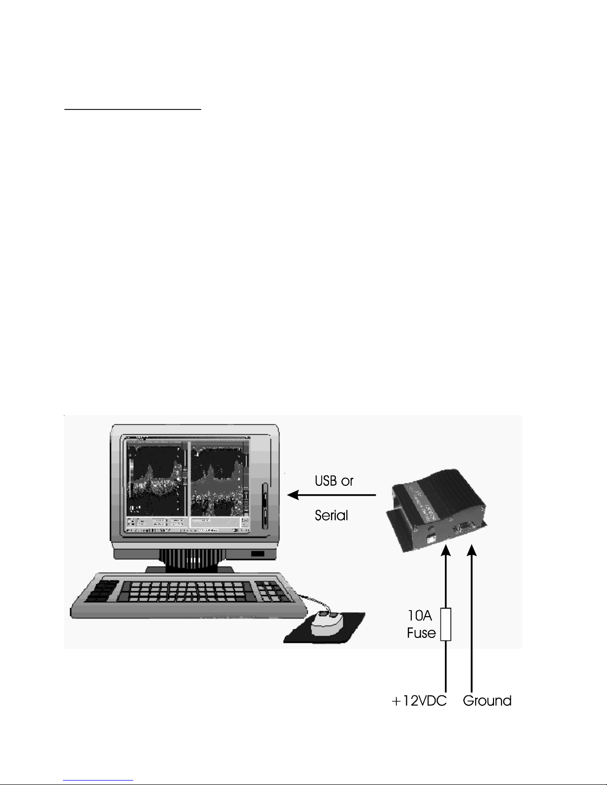
Mounting and Wiring
The Interface Box (“black box”) should be located in a dry area in where
the temperature does not exceed 50 deg C (120 deg F). The length of the
cable between the Interface Box and the PC should not exceed 2M (6
feet) in length. You have an option of connecting the Interface Box to
your PC with either a RS232 cable connected to a DB-9 nine-pin COM
port or a standard USB port.
The transducer comes supplied with a 6 pin Conexal female connector
that plugs into the 6 pin male Conexal connector on the Interface Box.
Two power leads (red and black) are also wired into the female transducer
connector and are used to power the Interface Box from a suitable +12VDC
power source as shown in Figure 1. The power source should be able to
supply the maximum current of 4.7 amps peak required during high power
Page 10
Figure -1 Red Black
Interface Box

Page 11
pulses. For protection, a 10 amp fuse should be connected in series with
the red +12V power lead. The wires supplying power to the Interface
Box should be heavy enough to carry 5 amps without dropping more than
one or two tenths of a volt. This will depend on the length of the wires
and Figure 2 will help guide you.
Figure 2 - Length From Interface Box to Power Supply
3 8 10 15 Meters
10 26 33 49 Feet
------------------------------------------
16 16 14 12 Gauge
Keep the Interface Box away from radios, radars, other electrical wires,
TV’s and antennas as much as possible to help prevent interference.
Transducer Installation
Plastic housings are recommended for fiberglass or metal hulls. Never
install a plastic Thru-Hull housing into a wooden boat hull. The swelling
of the wood may cause a fracture to occur. Bronze housings are
recommended for wood or fiberglass hulls. Never install a bronze housing
in a metal hull, because electrolytic corrosion can occur. Stainless steel
housings are recommended for metal hulls to prevent electrolytic corrosion
from occurring. Never install a metal housing in a hull with a positive
ground.
The transducer supplied for use with the PcFF80 is a dual frequency 50/
200Khz depth and temperature transducer. The use any other transducer
other than that expressly supplied with the PcFF80 will void the warranty
and can result in damage to the Interface Box. The transducers contain a
crystal element and care should be taken in handling the transducer so as

not to damage the sensitive transducer face. You should not coat the trans-
ducer face with antifouling paint. Mounting the transducer inside the boat
to “shoot through the hull” will result in less than optimal performance
and the use of an adhesive such as epoxy, glue, silicon adhesive or bed-
ding compound will void the transducer warranty.
A low profile plastic thru-hull transducer is supplied as standard with the
PcFF80 PC Fishfinder. Two different bronze thru-hull transducers or a
transom mount transducer are available as options. The following in-
structions are for installation of the plastic thru-hull transducer. Please
see the separate installation instructions provided with the other trans-
ducer options for the correct installation of those units.
The transducer should be located in an area of the boat hull that is free
from turbulence caused by thru-hulls, paddle wheels or any other
obstructions. It is important that the water flowing by the transducer face
be free of air bubbles caused by turbulence. If the hull is not parallel to
the water, then a suitable fairing block should be used to insure that the
transducer is mounter perpendicular to the sea bottom. On sailboats the
transducer should not be located too close to the keel.
In routing the cable to the sounder, avoid placing it near or parallel to
other electrical cables, particularly ignition and alternator wiring. Use care
when routing the cable through bulkheads and other parts of the vessel to
avoid tearing the cable jacket thus exposing it to the harsh environment.
Acoustic noise is another item to take into consideration when determining
a location of the transducer. Vessel generated noise from the propellers,
shafts and other machinery should be avoided also. After determining the
best location from the outside, consider the need for room inside the hull
to tighten the mounting nut and the need to route the transducer cable
away from other electrical noise generating wires..
Once a location has been determined, and prior to drilling any holes in the
hull. Inspect the location from the inside of the hole to ensure that the
Page 12

Page 13
location you have chosen will not interfere with any bulkheads, plumbing
or any other obstruction.
1. Drill a small hole first from the inside of the hull at the desired location
for the transducer. This will be a locating hole for the final drilling.
2. From the outside, enlarge the locating hole to ¼” or whatever size
necessary for the pilot drill of the 2” hole saw. Drill the pilot hole vertically,
followed by the hole saw.
3. After drilling, remove any rough edges around the hole and thoroughly
clean and sand the inside and outside surfaces around the hole.
4. Remove the wing nut from the transducer housing. Apply a generous
amount, approximately 1/16” thick, of a good marine adhesive/sealing
compound around the lip of the housing that contacts the hull. The
compound should also extend up the sidewall of the housing, ¼” higher
that the combined thickness of the hull and wing nut. This will ensure
there is sealant in the threads to seal the hull and to hold the wing nut
securely in place.
5. From the outside of the hull, insert the transducer housing and gently
rotate the housing to squeeze out any excess sealant.
6. From the inside, thread down the wing nut until it makes contact with
either the hull or fairing block, if used. The wing nut should then be
tightened to a snug fit, hand tighten only. DO NOT OVERTIGHTEN
THE WING NUT.
Note: For a cored fiberglass hull, thru hull transducer installation should
only be performed by a trained technician. Improper sealing of the core
material can lead to premature failure or possible water leakage.

Software Installation
Place the distribution CD into your CD/DVD drive and the install program
should launch automatically. If it does not, click on “Start”, “Run” and
type “D:\setup.exe” (substitute your CD ROM drive letter for “D” if your
CD ROM is on another drive than “D”).
Click OK and follow the instructions. Use the defaults unless you have a
good reason not to. If the installation was successful, you should see:
If you connect to the PcFF80 Interface Box with a RS232 serial cable and
one of your serial COM ports, then you can skip the following USB Driver
Installation section and proceed directly to the “Connecting a GPS” section.
Page 14
USB Driver Installation
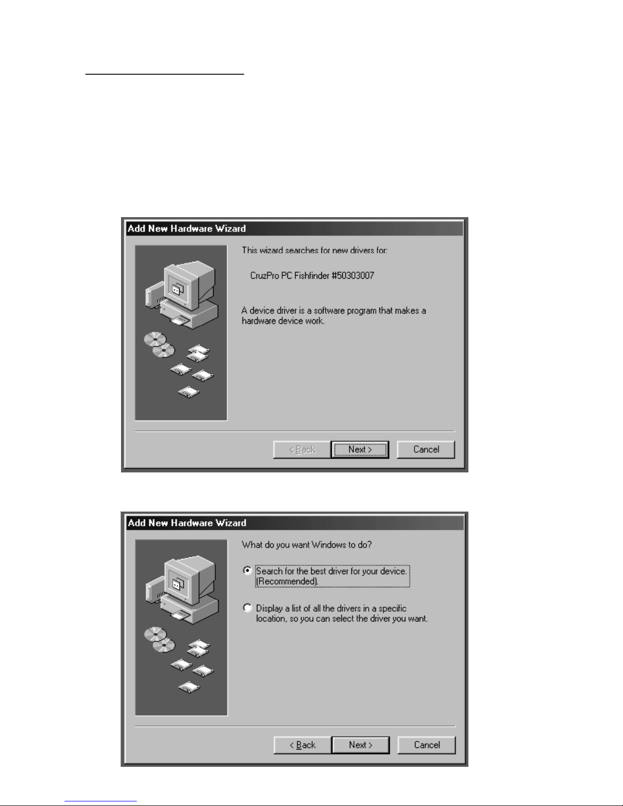
If you connect to the PcFF80 Interface Box with a USB cable, then you
will need to install and setup the appropriate USB driver software. Leave
the distribution CD in the CD ROM drive and plug a USB cable into the
Interface Box and your PC USB port. When you tun on the power to the
Interface Box, Windows will detect the new hardware and depending on
your version of Windows you will see a message similar to:
Click “Next” and “Next” again when you see:
Page 15

When the “Add New Hardware Wizard” comes up, click “Specify a loca-
tion”, type “D:\drivers” (substitute your CD ROM drive letter for “D”)
and click “Next”. Depending on your operating system Windows will
select a driver from the distribution CD. Click “Next” and the correct
driver will be automatically installed.
Page 16

Page 17
If the USB driver installation is successful, then you will see the follow-
ing screen. Click “Finish” to complete the installation of the USB driver.
After the USB driver has been installed, it must be optimized using the
Windows “Device Manager” before you can use the new driver. To get
into the Windows Device Manager:
In Win98: Click “START”, “Settings”, “Control Panel”, “System”,
“Device Manager”.
In WinXP: Click “START”, “Settings”, “Control Panel”, “Performance
and Maintenance”, “System”, “Hardware”, “Device Manager”.
In Win 2000: Click “START”, “Settings”, “Control Panel”, “System”,
“Hardware”, “Device Manager”.
In Vista: Click “START”, “Settings”, “Control Panel”, “System”, “Hard-
ware”, “Device Manager”.
The following screen will be displayed:

Select "View device by type" then click on "Ports (COM and LPT)" and
select "USB Serial Port (COMx)". Click the “Properties” button to bring
up the USB Serial Port properties page.
Click on "Port Settings", set "Bits per second" to 115200 and set “Flow
control” to None. Click the "Advanced" tab to display the next screen:
Page 18
None
None
None

Set the COM Port Number to the COM port number you want such as 3,
4, 5, 6, 7 or 8 (if they are not being used). Set the following parameters as
shown:
USB Transfer Sizes: Receive (Bytes) to 64
Transmit (Bytes) to 64
BM Options Latency Timer (msec) to 5
Options Disable PNP - checked.
Click OK until you get to the Device Manager and close it and any other
open windows (such as the Control Panel). This completes the USB
driver installation and setup.
If using the USB port, be sure to plug the USB connector into the PcFF80
Interface Box and your PC USB port and boot your PC before connect-
ing +12V power to the Interface Box. Turn off the power to the Interface
Box before removing the USB cable. Page 19

Regional Options
The PcFF80 Windows software expects to see numbers with a decimal
point not a comma. If the Regional Options in Windows is set to use
commas for numbers the software will not work. Use Control Panel -
Regional Options to set numbers to match the figure below.
Connecting GPS
The PcFF80 Windows software will display GPS latitude, longitude and
Speed Over the Ground (SOG) if a GPS is connected to your PC on COM1
to COM8. There are numerous ways to connect a GPS to your PC and
you should follow the GPS manufacturer’s instructions. The “Initial
Installation” section of this user’s manual will show you how to select the
GPS port. This port can be changed or disabled at any time with a few
clicks of the mouse from the PcFF80 Windows software.
Page 20
Table of contents
Popular Sonar manuals by other brands

Klein Marine Systems, Inc.
Klein Marine Systems, Inc. MA-X VIEW 600 Operation and maintenance manual

Lowrance
Lowrance X51 Installation and operation instructions

Humminbird
Humminbird 385ci DI Combo Operation manual

Tritech
Tritech Eclipse product manual

Furuno
Furuno DS-80 Operator's manual

Garmin
Garmin echo 200 Series owner's manual


Lowrance
Lowrance PRO X51 Installation and operation instructions

Humminbird
Humminbird 788ci NVB Compatibility listing

Marcum Technologies
Marcum Technologies LX-7L user manual

Lowrance
Lowrance 000-14012-001 quick guide

Furuno
Furuno COLOR SCANNING CSH-23F/24F Operator's manual

Simrad
Simrad SN90 quick start guide