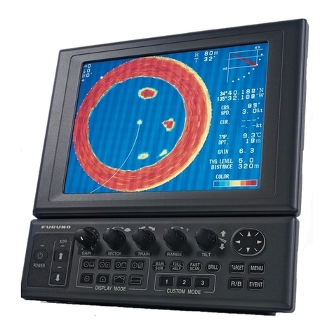
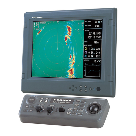
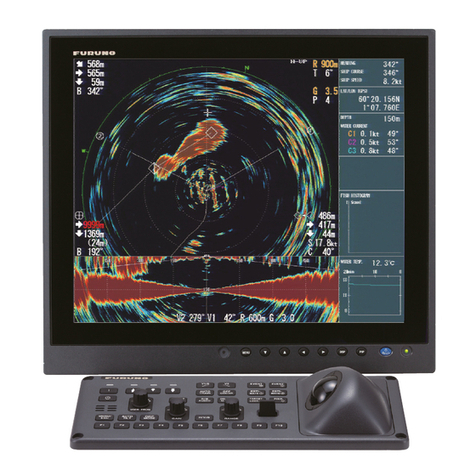
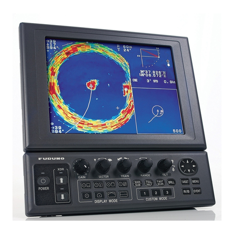
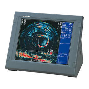
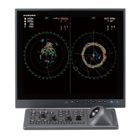
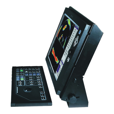
Furuno COLOR SCANNING CSH-23F/24F User manual

COLOR SCANNING SONAR
MODEL CSH-23F/24F
Back

The paper used in this manual
is elemental chlorine free.
Your Local Agent/DealerYour Local Agent/Dealer
9-52 Ashihara-cho,9-52 Ashihara-cho,
Nishinomi
y
a 662-8580, JAPANNishinomi
y
a 662-8580, JAPAN
Tele
p
hone :Tele
p
hone : 0798-65-21110798-65-2111
FaxFax 0798-65-42000798-65-4200
::
F
IRST EDITION :
F
IRST EDITION :NOVNOV.. 19971997
Printed in JapanPrinted in Japan
A
ll ri
g
hts reserved.
A
ll ri
g
hts reserved. GG :: FEBFEB.. 24, 200524, 2005
Pub. No.Pub. No. OME-13050OME-13050
*
00080818601
*
*
00080818601
*
*
00080818601
*
*
00080818601
*
(( DAMIDAMI )) CSH-23F/24FCSH-23F/24F * 0 0 0 8 0 8 1 8 6 0 1 ** 0 0 0 8 0 8 1 8 6 0 1 *
*
OME
13050
G
00
*
*
OME
13050
G
00
*
*
OME
13050
G
00
*
*
OME
13050
G
00
*
* O M E 1 3 0 5 0 G 0 0 ** O M E 1 3 0 5 0 G 0 0 *

i
SAFETY INSTRUCTIONS
WARNING
Do not open the equipment.
Hazardous voltage which can
cause electrical shock exists
inside the equipment. Only
qualified personnel should
work inside the equipment.
Immediately turn off the power at the
switchboard if water leaks into the
equipment or something is dropped in
the equipment.
Continued use of the equipment can cause
fire or electrical shock. Contact a FURUNO
agent for service.
Do not disassemble or modify the
equipment.
Fire, electrical shock or serious injury can
result.
Do not place liquid-filled containers on
the top of the equipment.
Fire or electrical shock can result if a liquid
spills into the equipment.
Do not operate the equipment with wet
hands.
Electrical shock can result.
Keep heater away from equipment.
A heater can melt the equipment's power
cord, which can cause fire or electrical
shock.
Immediately turn off the power at the
switchboard if the equipment is emitting
smoke or fire.
Continued use of the equipment can cause
fire or electrical shock. Contact a FURUNO
agent for service.
Make sure no rain or water splash leaks
into the equipment.
Fire or electrical shock can result if water
leaks in the equipment.
Use the proper fuse.
Fuse rating is shown on the equipment.
Use of a wrong fuse can result in equipment
damage.
WARNING

ii
CAUTION
Do not exceed 18 knots when operating
the equipment and do not exceed 16
knots when lowering or raising the
transducer.
The transducer may become damaged.
The zinc block attached near the
transducer must be replaced yearly.
The junction between the transducer and
main shaft may corrode, which can result
in loss of the transducer or water leakage
inside the ship.
Do not use the equipment for other than
its intended purpose.
Personal injury can result if the equipment
is used as a chair or stepping stool, for
example.
Do not place objects on the top of the
equipment.
The equipment can overheat or personal
injury can result if the object falls.
WARNING
To avoid electrical shock, do not
remove cover. No user-serviceable
parts inside. TYPE:86-003-1011-0
CODE No.:100-236-230
TYPE:03-160-1042-0
CODE No.:100-302-750
DANGER
Electrical shock hazard.
Turn off power before
servicing.
WARNING LABEL
Warning labels are attached to the equipments. Do not remove the lables. If the labels
are missing or damages, contact a FURUNO agent or dealer about replacement.

iii
TABLE OF CONTENTS
FOREWORD
AWord to CSH-23F/24F Owners...........................................................................................................vii
Features ...............................................................................................................................................vii
System Configuration ...........................................................................................................................viii
SYSTEM CONFIGURATION
Control Layout on Display Unit, Processor Unit and Remote Control Box ........................................... 1-1
Main Panel .......................................................................................................................................... 1-2
Sub Panel 1.......................................................................................................................................... 1-4
Sub Panel 2 (data setting window) ....................................................................................................... 1-5
Remote Control Box............................................................................................................................ 1-8
OPERATIONAL OVERVIEW
Turning the Power On/Off.................................................................................................................... 2-1
Adjusting Screen Brilliance, Control Panel Backlighting...................................................................... 2-1
Lowering the Transducer...................................................................................................................... 2-1
Selecting a Display Mode .................................................................................................................... 2-2
Selecting a Display Range.................................................................................................................... 2-3
Setting the Tilt Angle........................................................................................................................... 2-3
Adjusting the Gain............................................................................................................................... 2-7
Measuring Range and Bearing to a Target ............................................................................................ 2-7
FINE TUNING THE PICTURE
Eliminating Unwanted Feeble Echoes.................................................................................................. 3-1
Suppressing Seabed Tail....................................................................................................................... 3-3
Suppressing Seabed and Sea Surface Reflections in Shallow Waters..................................................... 3-4
Rejecting Sonar Interference and Noise................................................................................................ 3-4
Adjusting Beamwidth .......................................................................................................................... 3-6
MARKS AND DATA
Marks, Data and Display Mode............................................................................................................ 4-1
Permanently Displayed Marks and Data............................................................................................... 4-3
Erasable Marks and Data ..................................................................................................................... 4-4
MENU OVERVIEW
USER Menu Operation........................................................................................................................ 5-1
USER Menu Description...................................................................................................................... 5-3
SYSTEM Menu Description ................................................................................................................ 5-5
DATASET Menu Description.............................................................................................................. 5-8
INIT SET/TEST Menu Description.....................................................................................................5-11

i
v
FUNCTION KEYS
Programming the Function Keys...........................................................................................................6-1
Replaying a Function Key.....................................................................................................................6-2
Function Key Fine Tuning ....................................................................................................................6-2
Saving Function Key Settings to a Memory Card..................................................................................6-3
Replaying Function Key Settings from a Memory Card.........................................................................6-3
ADVANCED LEVEL OPERATION
Finding Fish School Center...................................................................................................................7-1
Tracking a Fish School (target lock)......................................................................................................7-2
Detecting Fish Schools Aurally.............................................................................................................7-7
The Fish Alarm.....................................................................................................................................7-8
Relocating Fish School for Easy Observation........................................................................................7-9
Comparing of Fish School Concentration............................................................................................7-10
Measuring Fish School Speed.............................................................................................................7-11
The Event Mark..................................................................................................................................7-12
True Motion Display...........................................................................................................................7-14
Plotting Net Location Mark.................................................................................................................7-15
Observing Net Behavior......................................................................................................................7-16
Target Slice Display............................................................................................................................7-17
VERTICAL SCANNING DISPLAY
Using Vertical Scanning Display...........................................................................................................8-1
Application to Bonito and Tuna Fishing................................................................................................8-2
PORT/STARBOARD, HORIZONTAL SLICE DISPLAYS
Port/Starboard display...........................................................................................................................9-1
Horizontal slice display.........................................................................................................................9-2
MEMORY CARD OPERATIONS
Initializing Memory Cards..................................................................................................................10-1
Saving the Picture...............................................................................................................................10-2
Transferring Echo Data from Internal Memory to Memory Card.........................................................10-2
Saving Net Shooting Data...................................................................................................................10-3
Replaying Saved Data.........................................................................................................................10-4
Deleting Memory Card Contents.........................................................................................................10-4
TURNING MARKS, DATA ON/OFF.................................................................11-1
INTERPRETING THE DISPLAY
Seabed Echoes....................................................................................................................................12-1
Fish Schools .......................................................................................................................................12-2
Sea Surface Reflections ......................................................................................................................12-3
Wake..................................................................................................................................................12-3
False Echo by Sidelobe.......................................................................................................................12-4
Noise and Interference........................................................................................................................12-4

v
WARNINGS
Overvoltage Warning...........................................................................................................13-1
Unretracted Transducer Warning.........................................................................................13-1
SELF TESTS
Opening the Self Test Menu ................................................................................................14-1
Self Test Description............................................................................................................14-2
Interface Unit CS-120A Self Test........................................................................................14-5
INPUT DATA SELECTION
Selection of Data at Interface Unit CS-120A.......................................................................15-1
Setting Distances Between Net Sonde Transmitters............................................................15-2
MAINTENANCE
Display Unit Maintenance....................................................................................................16-1
Hull Unit Maintenance.........................................................................................................16-2
Replacement of Fuse, Memory Card Battery.......................................................................16-3
MENU TREE...................................................................................................... A-1
SPECIFICATIONS...........................................................................................SP-1
INDEX .............................................................................................................. IN-1

This page is intentionally left blank.

vii
FOREWORD
A Word to CSH-23F/24F Owners
Congratulations on your choice of the FURUNO CSH-23F/24F Color Scanning Sonar.
We are confident you will see why the FURUNO name has become synonymous with
quality and reliability.
For over 50 years FURUNO Electric Company has enjoyed an enviable reputation for
quality marine electronics equipment. This dedication to excellence is furthered by our
extensive global network of agents and dealers.
This equipment is designed and constructed to meet the rigorous demands of the
marine environment. However, no machine can perform its intended function unless
operated and maintained properly. Please carefully read and follow the recommended
procedures for operation and maintenance.
We would appreciate hearing from you, the end-user, about whether we are achieving
our purposes.
Thank you for considering and purchasing FURUNO equipment.
Features
The CSH-23F/24F is a full-circle, multibeam electronic color scanning sonar which
detects and displays fish schools on a 15/21 inch non-glare, high-resolution color CRT.
Also, the CSH-23F has two types of models: a model with display unit and a model with
processor unit and no monitor (monitor is supplied by user).
The main features of the CSH-23F/24F are
• Vivid 16-color, echo strength dependent display for improved recognition of seabed,
fish school concentration, distribution and volume.
• Memory card for storage and replay of sonar picture (whole screen or echo inside
estimate mark), net shooting data, ship’s track, tidal current data, etc.
• Function keys for customized operation.
• Menu-driven operation with help screen.
• Wide variety of display modes: normal sonar picture, echo sounder combination,
historical display combination, port/starboard display, horizontal slice, target slice,
and unique vertical scanning.
• Various marks and alphanumeric fishing information for intuitive operation.
• Remote control box for armchair control of major functions.
• High power MOS FET transmitter for reliable operation.
• Automatic screen degausser

viii
System Configuration
STANDARD OPTION
REMOTE CONTROL BOX
CSH-116
DISPLAY UNIT
CSH-230F (CSH-23F)
MONITOR (MU-151C)
or
COMMERCIAL MONITOR
SUB DISPLAY*
CSH-236
STEP-DOWN
TRANSFORMER
PT-400
INTERFACE UNIT
CS-120A
VI-1100A
INTERFACE UNIT
FNZ JOINT BOX
CS-170
TRANSMITTER UNIT
CSH-310
SHIP'S MAINS
100 VAC, 1
φ
,
50/60 Hz
110/115/220/230 VAC,
1
φ
, 50/60 Hz
SPEED LOG
NAVIGATOR
CURRENT INDICATOR
COLOR VIDEO SOUNDER
AD CONVERTER
ECHO SOUNDER, COLOR
VIDEO SOUNDER
NET SONDE
SHIP'S MAINS
100 VAC, 1
φ
,
50/60 Hz
SHIP'S MAINS
100/110/220 VAC, 1
φ
,
50/60 Hz
or
PROCESSOR UNIT
CSH-235F
HULL UNIT
CSH-21080 (800 mm stroke)
CSH-21120 (1200 mm stroke)
CSH-2400F (CSH-24F)
POWER
SUPPLY UNIT
CSH-380B RECEIVER UNIT CSH-220A
CSH-21160 (1600 mm stroke)
*: CSH-23F only

1-1
CONTROL DESCRIPTION
Control Layout on Display Unit, Processor Unit and
Remote Control Box
POWER TRANSDUCER
OFF ON
F1 F2 F3
-
+
NORM E/S HIST RECALL MEMO
TARGET
SLICE
SHOOT R/B
-
+
-
+
RANGE GAIN
AUTO
TILT
WIDTH
TILT
SCAN DEPTH
DIM CONT BRILL AUDIO
NET
COURSE TARGET
LOCK
EVENT1 EVENT2
ESTI-
MATE1 ESTI-
MATE2
FISH OFF-
CENT
PUSH-OPEN
VERT
SCAN
Same as Sub-panel
of the display unit
*: The contrast and billiance
controls are disable. Adjust
them at a monitor.
+-
+-
+-
+-
+-
+-
DISP
POWER TRANSDUCER
OFF ON
F1 F2 F3
-
+
NORM E/S HIST RECALL MEMO
TARGET
SLICE
SHOOT R/B
-
+
-
+
RANGE GAIN
AUTO
TILT
WIDTH
TILT
SCAN DEPTH
DIM CONT BRILL AUDIO
NET
COURSE TARGET
LOCK
EVENT1 EVENT2
ESTI-
MATE1 ESTI-
MATE2
FISH OFF-
CENT
VERT
SCAN
SUB PANEL 1
MAIN PANEL
SUB PANEL 2
*
Display unit Processor unit
(CSH-23F only)
123
DISPSELECT DATA
EVENT TGTLOCK
ESTIMATE
1
NETCOURSE
FISH
OFF-
CENT
TX
1234
FUNCTION
5
+
RANGE
+
GAIN
SHOOT MEMO
TGT
SLICE
RECALL
AUTO
AUTO
BOOST TILT
TRAIN
SCANDEPTH
-
-
Remote control box
Figure 1-1 Display unit, processor unit and remote control box

1-2
Main Panel
POWER TRANSDUCER
OFF ON
F1 F2 F3
-
+
NORM E/S HIST RECALL MEMO
TARGET
SLICE
SHOOT R/B
- +- +
RANGE GAIN
AUTO
TILT
WIDTH
TILT
SCAN DEPTH
DIM CONT BRILL AUDIO
NET
COURSE TARGET
LOCK
EVENT1 EVENT2
ESTI-
MATE1 ESTI-
MATE2
FISH OFF-
CENT
VERT
SCAN
Figure 1-2 Main panel
Main panel control description
lortnoCnoitcnuF
,NOREWOP FFOREWOP xTgnirudsthgilyekehtevobapmalehT.metsysehtnosnruT:NO .ffodenrutsi1lenapbusniyekXTehtnehwsknilbdna .recudsnartehtgnitcarterretfasserP.metsysehtffosnruT:FFO
RECUDSNART sedivorpyekworranwodllamsehT.recudsnartehtrewoldnaesiaR PUehT.noisurtorplluf,yekworranwodegraleht;noisurtorp-dim worra.recudsnartehtsesiar
]+[,]-[,3F-1F .gninutenifedivorp]+[,]-[.margorpresuotgnidroccayalpsidpusteS

1-3
Control Function
NORM, E/S, HIST
(Mode keys) Select display mode: NORM, normal sonar picture; E/S, Echo sounder
combination; HIST, Historical display.
Lamp above a key lights to show current selection.
RECALL, MEMO RECALL: Replays saved picture.
MEMO: Saves picture to memory card or internal memory.
RANGE Selects a picture display range. Range selected appears on the display.
GAIN Adjusts receiver sensitivity.
TARGET SLICE Using automatic tilting, displays the echo inside the estimate mark at
several different tilt angles.
VERT SCAN Turn vertical scan display on and off.
SHOOT Press when net is cast. The net shooting mark, *net sonde marks and
*current mark appear at the own ship mark. The net shooting mark,
net sonde marks and current mark move on the *ship's track as the
ship moves. The lamp above the switch lights and time *distance run
appears on the display until the net shooting mark is turned off.
(* Requires external sensor.)
R/B Provides range and bearing data from own ship to a target. Select
target with trackball and then press the R/B key. A line connects
between own ship mark and trackball mark to show bearing to target.
TILT Changes the tilt angle of the sounding beam between -5°and 60°.
AUTO TILT Automatically tilts the sounding beam up and down in 2°steps within
the tilt angle selected by the WIDTH key. The lamp above the key
lights when automatic tilt is on.
WIDTH Sets tilt width in automatic tilt.
NET COURSE Marks location of net.
TARGET LOCK Tracks a fish school.
EVENT Inscribe event mark on the display, to find horizontal, range, depth
and bearing to a target. Event key can be functioned as the SHOOT
key of the remote control box.
ESTIMATE 1, 2 Compare volume of two fish schools.
FISH Measures fish school speed.
OFF-CENT Relocates selected target. Lamp above key lights when off-center
function is on.
DIM Adjusts the backlighting of the control panels and the brightness of
the lamps above keys.
CONT Adjusts screen contrast.
BRILL Adjusts screen brilliance.
AUDIO Adjusts volume of built-in loudspeaker, which monitors a target
appearing along the bearing marker.
TRACKBALL Follows on-screen movement of the trackball mark, to enter marks
and off-center the screen.

1-4
Sub Panel 1
RECALL MEMOHISTE/SNORM
F4 F5F3F2F1
ONOFF
POWER TRANSDUCER
CARD
REPLAY COLOR NET
REPLAY TX
HELP
END
MENU
Figure 1-3 Sub panel 1
Sub panel 1 control description
Control Function
MENU Opens/closes the menu.
END • When the menu is displayed it terminates menu operation and
returns control to the sonar picture.
• When in a sub menu it returns control to previous sub menu.
HELP Provides operating information for current menu.
cd[ \ Select items on menus.
CARD REPLAY Replays card-stored control and menu settings.
COLOR Changes display color among four choices.
NET REPLAY Replays internally stored net shooting data. To replay, press key to
light lamp above it, select item to replay, and press the key again.
TX Press to transmit, when transducer is lowered. The lamp lights during
transmission.

1-5
Sub Panel 2 (data setting window)
SIGNAL
DELETE MK
ES
SONR
Q
BEAM
AUTO
ALM
Q
AUDIO
NEAR
7
MEDIUM
8
FAR
9
CYCLE
7
PL
8
OUTPUT
9
TVG TX
+ + + + + +
- - - - - -
OPER
P-SET
(TOGGLE)
Setting change keys
Change control setting.
Item selection keys
Select item.
OPER P-SET key
Opens/closes data setting window.
ITEM
(TVG
Q
TX selected)
CURRENT SETTINGS for item selected (TVG
Q
TX)
This example shows settings
of TVG and TX.
TVG
Q
TX
Figure 1-4 Sub panel 2
Note: The sub-panel 2 for the processor unit is arranged vertically.
Sub panel 2 control description
Item
Main
Item Main Sub
Setting
Range Description Normal
Setting
NEAR 0-9
Adjusts receiver gain within
100 m. 5
MEDIUM 0-9 Adjusts receiver gain between
100 m and 400 m. 5
TVG
FAR 0-9
Adjusts receiver gain beyond
400 m. 5
CYCLE 0-9
Sets Tx cycle. 9 is normal setting
(fastest). “0” synchronizes with
external KP.
9
PL 0-9
Sets Tx pulselength. 9 is normal
setting. 9
TVG ●TX
TRANSMIT
OUTPUT 0-9 Sets Tx output power. 9 is
maximum power. 9
(Continued on next page)

1-6
niaM metI metI gnitteS egnaR noitpircseD lamroN gnitteS
niaMbuS
LANGIS
LANGIS
SSECORP
LN01–0.seohcedetnawnustcejeR3
CGA01–0
reviecersecuderyllacitamotuA hcusseohcegnortstsniaganiag siohcehsifostsujdA.debaessa .debaesraendeyalpsid
0
*CGA2
-
5+ot4
RA
fI.seohcedebaessesserppuS sserppustonnacenolaCGA .CGA2esu,seohcedebaes 0
LANGIS
SSECORP
EVRUC4–1
-neserpsusrevlevelohcestceleS rehgihehT.evrucrolocnoitat eesotsitireisaeeht,gnitteseht .neercsehtnoseohcekaew
2
RI3–0 -retnidnaesionmodnarstcejeR srednuosohcerehtoybecneref
.sranosro 0
WOLGFA4–0
sihcihw,wolgretfaohcestsujdA -evomohcegnihctawroflufesu ehtgnittesehtrehgihehT.tnem .sniamerwolgretfaehtregnol
0
SE
1SE
teN(
)redroceR
EGNAR
)GNRND(61
.soP
ohcefoegnarhtpedsteS foegnarsteS.erutciprednuos drawnwodredrocerten
.gnidnuos
m061
NIAG01–0.ytivitisneseviecerstsujdA5
TFIHS
)GNRPU(
–0
m0001
ohcefohtpedtratsyalpsidsteS
foegnarsteS.erutciprednuos
.gnidnuosdrawpuredrocerten m0
1SE
teN(
)redroceR
LN01–0 ybdesuac(stodeulbstcejeR .neercseritneno)retawytrid 0
ROLOC9–0 nideyalpsidseohcesetanimilE
.deificepssroloc 0
RI ,NO
FFO rehtoybecnerefretnisetanimilE .srednuosohcerosranos FFO
KMETELED
ETELED
KRAM
-ro+
otyek
.esare
kramtsedlosesaregnisserphcaE tneve,kramtnevegnoma pihsnwo,kramhsif,kram
.kram
ETELED
KRAM KCART fo5/1seteledgnisserphcaE
.htgnelllarevo
HSIF.deteledsikcarThsiF
*2AGC and HOR functions cannot be used together. If one is used the other is
automatically set to “0”.
(Continued on next page)

1-7
niaM metI metI gnitteS egnaR noitpircseD lamroN gnitteS
niaMbuS
MAEB•RNOS
RANOS
RANOS2–1 ro,ranoselgnisrof"1"esoohC .ranoslaudrof"2" 1
TFIHS-F2–1 "1"esoohC.ycneuqerfxTstfihS .esulamronrof 1
MT/PU edomnoitatneserpstceleS gnidaeH,)puN(pu-htroNgnoma .)MT(noitoMeurT,)puH(pu puH
MAEB
*ROH01–0 xRfohtdiwmaeblatnozirohsteS ,rebmunehtrehgihehT.maeb .maebehtreworraneht 0
REV4–0
fohtdiwmaeblacitrevsteS lamronsi"0".maebnoissimsnart ediwrof"2"dna"1".gnittes ecafrusecuderot"3";maeb eslafsserppusot"4";rettulc .seohcemottob
0
OTUA
OTUA TLIT
FFO/NOFFO,NO.elgnatlitgninnacsffo/nosnruTFFO
HTDIW :EDIW ±01-2 °,±61-4 °,±02-6 °
:WORRAN ±4-1 °,±6-2 °,±8-3 °
±2°–±01
°
OTUA NACS
FFO/NOFFO,NO ,LBEgninnacsffo/nosnruT .rotcesoiduasnacshcihw FFO
HTDIW gninnacscitamotuasesoohC gnomahtdiw ±01 °,±02 °,±04 °
dna ±06 °.±01 °
OIDUA•MLA
HSIF MRALA
FFO/NOFFO,NO.ffo/nomralahsifsnruTFFO
LEVEL51–0
hsifhcihwtalevelohcesteS 51–0srebmuN.sdnuosmrala noitatneserp61otdnopserroc hsidder,51,eulbpeed,0:sroloc .nworb
01
ENOZ -/+sserP .yek ehtgnisu,enozmralasteS .yek+dnallabkcart
OIDUA
ROTCES gnomarotcesoiduasesoohC03 °06, °09, °081, °033dna °.03 °
BREVER9–0 noitarebreverfohtgnelsesoohC sevigrebmunregraL.oiduarof .noitarebreverregnol 0
RETNEC -/+sserP .yek ,rotcesoiduafonoitceridsteS .yek+dnallabkcartehtgnisu
*HOR and 2AGC functions cannot be used together. If one is used the other is
automatically set to “0”.

1-8
Remote Control Box
123
DISPSELECT DATA
EVENT TGTLOCK
ESTIMATE
1
NETCOURSE
FISH
OFF-
CENT
TX
1234
FUNCTION
5
–
+
RANGE
+
–
GAIN
SHOOT MEMO
TGT
SLICE
RECALL
AUTO
AUTO
VERT
SCAN
TILT
TRAIN
SCANDEPTH
Each press displays water
temperature or depth at screen
center for about five seconds.
Turns on transmitter.
Shifts trackball mark.
1-3: Same as 1-3 on main panel.
4-5: Same as - and + on main panel.
Displays the net shooting mark.
Saves picture to memory card.
Present a four (or five) angle view of
echo inside estimate mark. Light switch
to start.
Varies the tilt angle of the
sounding beam between -5°
and 60°.
Automatically tillts sounding
beam in 2°steps within tilt
angle selected by the WIDTH key.
Not used.
Not used.
Adjusts receiver sensitivity.
Selects display range.
Press to enter mark
shown on key or shift
screen center.
ises/lowers the transducer.
: Raises transducer.
: Mid protrusion
: Full protrusion
elects which display unit to
ontrol in multiple display unit
stallation.
Replays a stored picture.
➡
➡
➡
Figure 1-5 Remote control box

2-1
OPERATIONAL OVERVIEW
Turning the Power On/Off
Turning the power on
Press the ON switch on the main panel. The lamp above the
switch should light. If it doesn’t press the TX switch on sub
panel 1.
Turning the power off
Retract the transducer with the cswitch and then press the OFF
key on the main panel.
Note:The transducer isautomatically retractedinto thetank even
if the OFF switch is pressed before retracting the transducer.
However, make it a habit to retract the transducer before turning
off the power.
Adjusting Screen Brilliance, Control Panel Backlighting
The BRILL control adjusts screen brilliance, and the DIM con-
trol adjusts control panel backlighting. These controls are on the
lower part of the main panel.
Lowering the Transducer
Press dor dswitch. The lamp above the
switch blinks during lowering of the trans-
ducer and lights when the transducer is
completely lowered. In normal use fully
lower the transducer. The transducer ex-
tends *1200 mm below the ship’s hull, pro-
vidingstable andcavitation-free soundings.
If the transducer may become entangled in
the net, after shooting the net, for example,
partially raise the transducer with the d
switch. This raises the transducer by 400
mm (transducer extends *800 mm from
ship’s hull).
*Hull unit with 1600 mm (full) and 1200
mm (mid) protrusions are also available.
CAUTION
Do not exceed speed noted in the speci-
fications when operating the equipment
or lowering or raising the transducer.
The transducer may become damaged.
Do not press the cswitch during
lowering of the transducer, and do not
press the
d
or dswitch during raising
of the transducer.
The equipment may become damaged.

2-2
Selecting a Display Mode
The CSH-23F/24F provides three display modes: normal sonar
picture, echo sounder (E/S) combination, and history display
combination. Those modes may be selected with the NORM, E/
S and HIST keys.
Table 2-1 Display mode description
Mode Description
The sonar picture appears over the entire screen.
This mode is useful for detecting and tracking fish
schools.
The default display area is 1.3 times
the range, but it can be changed to
1.6 times the range on "EXT KP/TM
DSP" in the SYSTEM menu.
Navigation information can be
displayed in the text window at
the screen bottom by turning on
"DATA DISPLAY" in the USER
menu.
Normal scanning picture appears on the upper 5/8
of the screen and the signal fed from the echo
sounder on the lower 3/8. This mode is suitable for
judging fish school concentration.
When two echo sounders are connected, each
pressing of the E/S key alternately selects echo
sounder 1 or echo sounder 2.
Note that a net recorder can be connected as echo
sounder 2; select it on the "ES" sub menu in the
INIT SET/TEST menu.
Normal scanning sonar picture appears on the upper
5/8 of the screen and the history display on the
lower 3/8. Three types of history displays are
available: Audio, Port/Starboard and Horizontal
Slice. You can select which one to display on the
USER menu.
NORMAL
E/S
HISTORY
Text window
This manual suits for next models
2
Table of contents
Other Furuno Sonar manuals

Furuno
Furuno TS-331A User manual

Furuno
Furuno DS-60 User manual

Furuno
Furuno COLOR SCANNING CSH-55 User manual

Furuno
Furuno FE-1280 User manual

Furuno
Furuno CH-28 User manual

Furuno
Furuno CSH-5L User manual

Furuno
Furuno CH-300 Manual

Furuno
Furuno CSH-83 User manual

Furuno
Furuno CH-250 User manual

Furuno
Furuno DS-60 User manual
Popular Sonar manuals by other brands

Interphase
Interphase Sea Scout Operation manual

Lowrance
Lowrance X-25B Installation and operation instructions

Simrad
Simrad SH90 - REV A datasheet

Kongsberg
Kongsberg SBP 29 installation manual

Humminbird
Humminbird 610 Installation and operation manual

Eagle
Eagle ID-6300 Installation and operational manual