Crystal Mountain Storm Cafe User manual
Service Manual
Storm Café
Hot, Cold and Coffee Dispenser

2
Notes

3
SECTION 1: Product Specification 4
Dimensional Drawing 5
Description of Product Model Number 6
SECTION 2: Parts Listing and Exploded Views 7
Parts Listing 7
Exploded Views 8
Fluid Path Diagram 9
Wiring Diagram 9
SECTION 3: Water Bottle Installation and Replacement 10
SECTION 4: Replacement of SmartFlo™ System 14
SECTION 5: Electrical Diagnosis and Replacement 17
Cold Control Replacement 17
Cold Control Adjustment 19
Hot Thermostat/Limiter Replacement 20
Hot Tank Replacement 21
Compressor Relay/Overload Replacement 24
SECTION 6: Cleaning & Sanitization 26
Cleaning and Sanitizing the Water Cooler 26
Monthly Cleaning and Sanitizing of the Brewer 31
Clearing the Inlet or Outlet Needle 32
SECTION 7: Displaying and Clearing Fault Codes 34
SECTION 8: Purging Water from System 35
SECTION 9: Troubleshooting 36
CAUTION: Optimum Operating Range 50°F-90°F (10°C-32°C)
Table of Contents

4
The Storm Café water dispenser with coffee brewer is the latest model
in the Storm family of coolers. The Café combines the convenience of
the original Storm bottom load cooler with a single serve coffee cup
type brewer. This generation of the Storm has an upgraded fascia with
lighting over each faucet handle.
Specifications
Storm Café
Power Rating Single Phase
100-115VAC 60Hz
Standard Current 8.9~9.5A
Power Cold 70W
Consumption Hot 1000W
Cold
Compressor Single Phase Compressor
Refrigerant Type R134a (32g)
Temperature Range 4-10°C(39.2-50°F)
Hot/Coffee
Heater Internal Heater
Temperature Range 73.9°C -85°C (165°F -185°F)
Temp. Range for Coffee 91.5°C (196.7°F)
Safety Device Bimetal (Limiter115°C (239°F) OFF)
Temperature Control Bimetal 95°C (203°F)
NTC Control Electronic
Net Weight 15.1kg (33.1 lb.)
Loading Quantity 20’ Container: 204 Units
40’ container: 420 Units
5
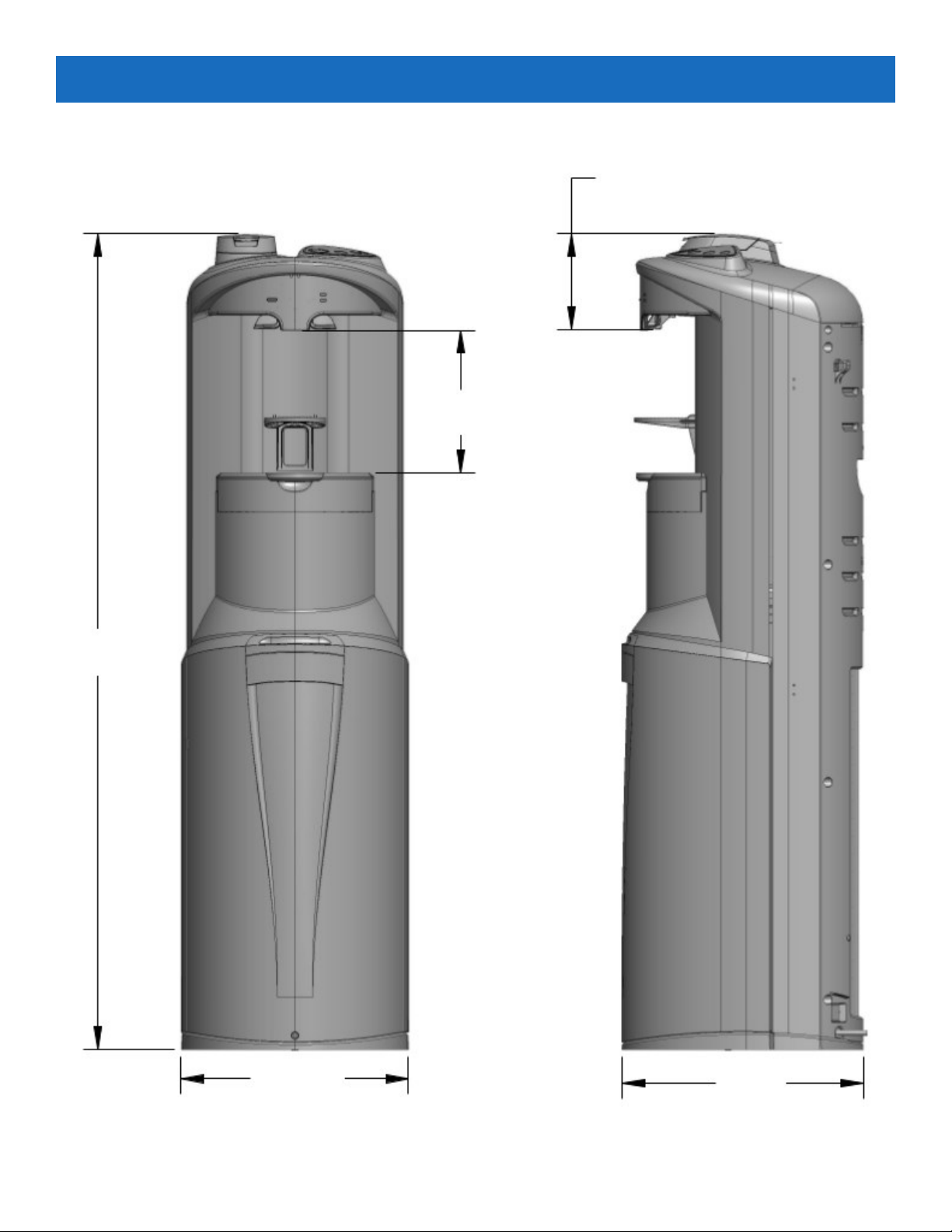
Dimensional Drawing
45.172 (1147.37)
7.904 (200.76)
5.273 (133.93)
12.598
(319.99)
13.386
(340)
Dimensions are shown in Inches (mm)

6
The model and serial number can be found on the rear of the cooler.
See the example to right.
AB FM2KHK 1
Cooler Shape Reservoir Type Type of Lid # of
Faucets
Body Color Temp.
Option
Insert Color Voltage Option
AB=
Storm Coffee
Brewer
F=
SmartFlo™
Water
Cartridge
M=
Manifold
2K=
Black
H=
Hot & Cold
K=
Black
1=
115V
CF=
Café
Description of Product Model Number

7
DESCRIPTION ABFM2KHK1CF
1. Tube Guide, Hot PLC-C150176
2. Handle Assembly (contains hot & cold handles) SUB-G300001
3. Spring, SS, Faucet FAS-C100104
4. Pin, Handle 76mm FAS-C100199
5. Flow Meter ELE-C100489
6. Tube, Silicone, Flow Meter SIL-C150043
7. Connector, Water, Female PLC-C150167
8. Valve, One Way POU-C100100
9. Cover, Pump PLC-C150174
10. Tube, Silicone, Air Pump SIL-C150032
11. Pump, Air, DC12V ELE-C100436
12. Cover, RJ11 PLC-C150177
13. Upper Shelf Assembly SUB-C200632
14. Cold Control REF-C100035
15. Motor, 12V DC, 1600 RPM ELE-C100204
16. Bushing, Motor PLC-C150052
17. Door Rail, Cap PLC-C150033
18. Latch, SmartFlo, Cafe PLC-C150166
19. Spring, SS, Safety Button FAS-C100116
20. Safety Button, Red PLC-C150126
21. PCB Switch Board ELE-C100421
22. Top Cover Assembly (8, 10, 12 oz brew size) SUB-C200722
Top Cover Assembly (6, 8, 10 oz brew size) SUB-C200839
23. Pod Holder PLC-C150162
24. Housing, Rear Café Assy SUB-C200640
25. Housing, Front, Café Assy SUB-C200642
26. Steam Valve, Café SUB-C200634
27. Solenoid Valve SUB-C200638
28. Base, Café Module Assy SUB-C200639
29. Cover, Power PCBA PLC-C150188
30. SmartFlo, Single Pack SUB-C200724
31. Hot Tank Assembly SUB-C200628
32. NTC, White ELE-C100457
33. NTC, Red ELE-C100452
34. Limiter ELE-C100459
35. Thermostat, Sealed ELE-C100458
36. Drain Cover PLC-C150216
37. Plug, Drain, Yellow SIL-C100154
38. Drain Cap PLC-C100399
39. Drain Fitting PLC-C150121
40. Spring Clip FAS-C000029
41. Tube, Drain SIL-C150002
Parts Listing
8
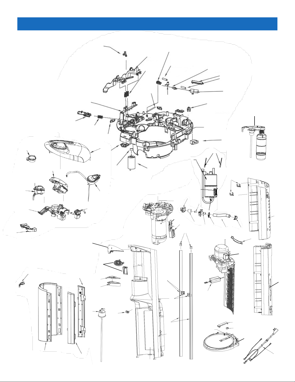
Exploded View
1
2
3
47
5
68
9
10
11
12
13
14
15
16
17
18
19
20
21
22
25
24
23
26
2728
29
30
31
32, 33
31
34, 35
36
37
38 39 40 41 42
43
44
45
47, 48
46
49
50
51
52, 53
54 55
56
58
57
59 60
61
62
63
64
65
66, 67
68
69
70
73
71
72

9
Fluid Path Diagram
Electrical Diagram
SmartFlo
Water
Pump
Cold Water
Dispense
Hot Water
Dispense Coee
Dispense
Bole
Pinch
Valve
Pinch Valve
Hot
Tank
Solenoid
Coee Pod
Brewer Head Brewer
Housing
Air Pump
One-Way
Valve
Flow
Meter
Steam Valve
Cold
Reservoir
Brewer
Lid
Switch
Connector
Blk
Hot Switch
Coee UI PCBA
Power Cord
Hot
Tank
Limiter
Hot Thermostat
Cold Control
Heater Control
PCBA
Blk
Blk
White
G/Y
G/Y White
White
White
Transformer To Overload
To Relay
Compressor
Flow Sensor
Lid Switch
LED FPC
LED Panel
MAIN PCBA
Switch PCB
Switch PCBA
Intensity SW
Water Pump
Solenoid
Air Pump
Bole SW
BK
Yellow
Blue Thermistor Dispense
Thermistor Control
Red
White
NTC
Red
NTC
10
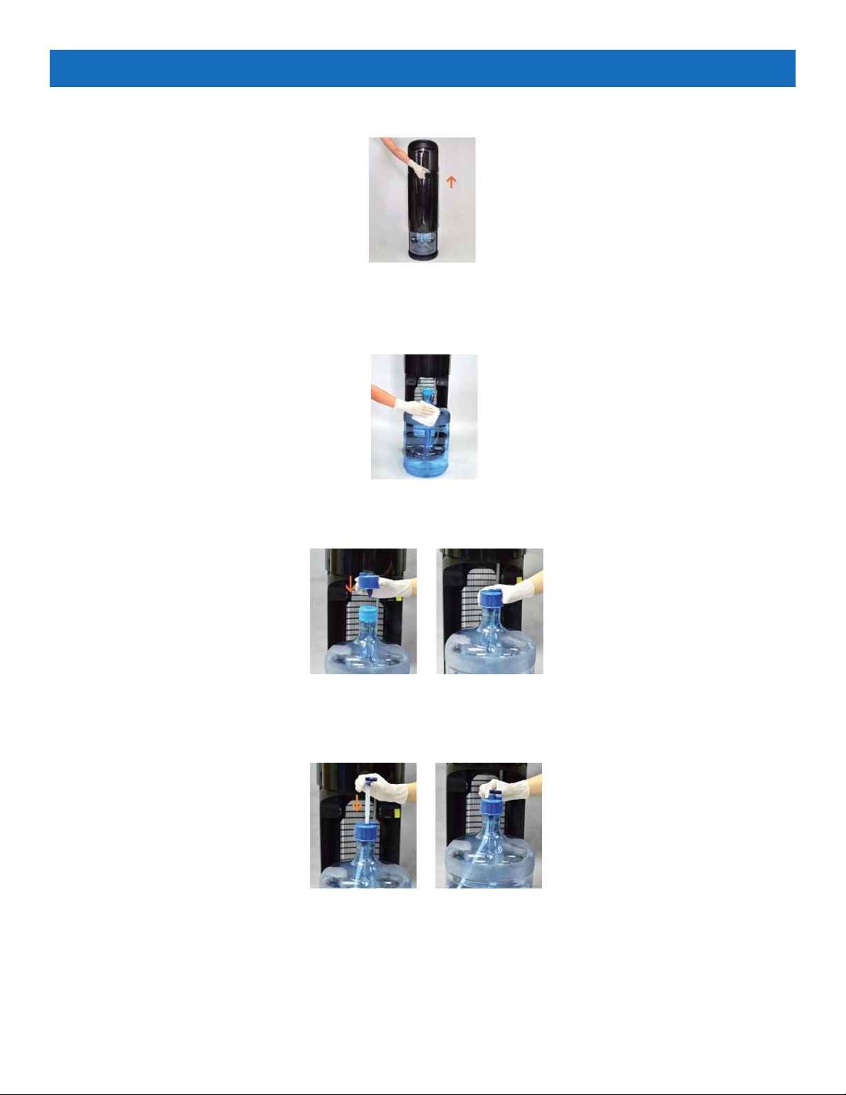
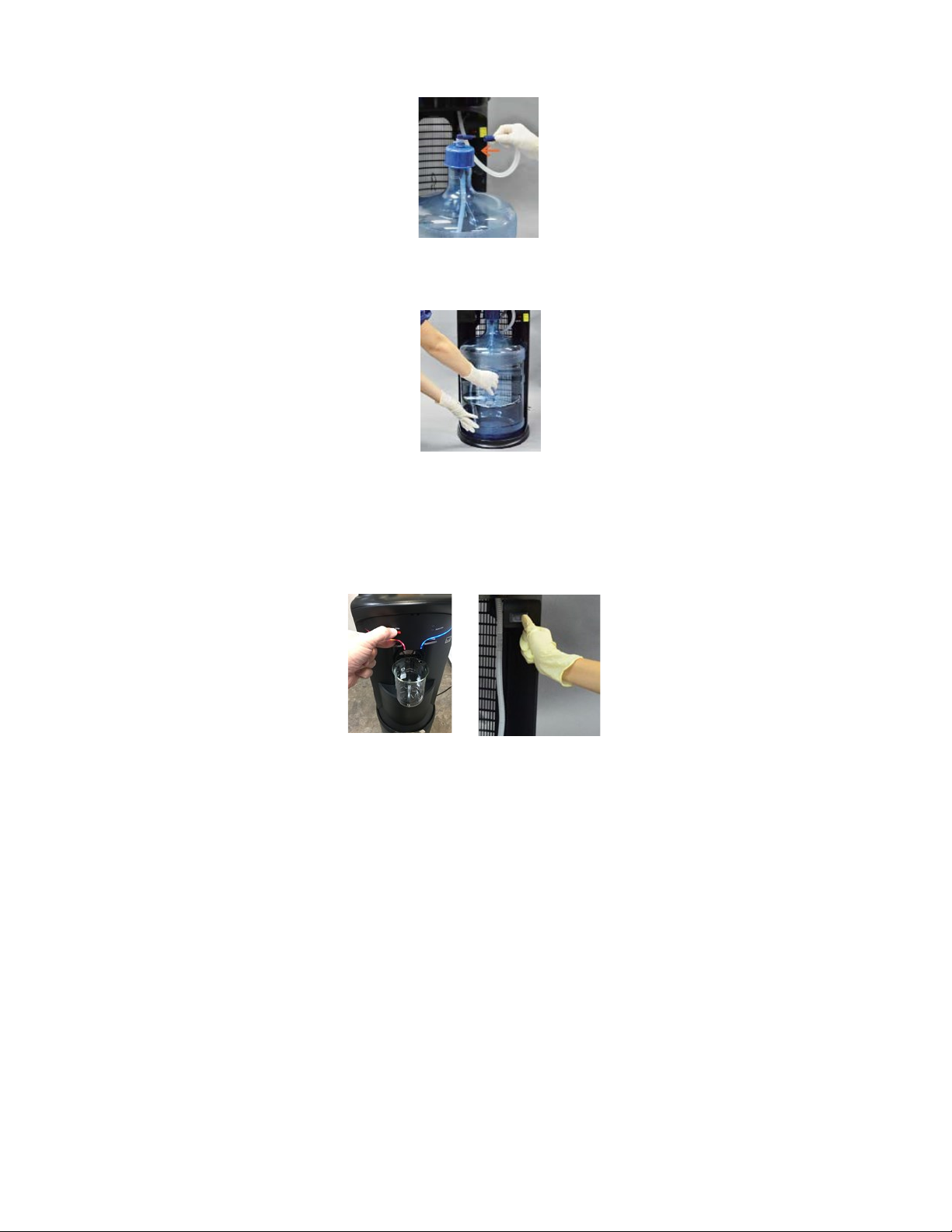
1. Open Dispenser door (Fig.1). Slide door upward to access bottle area.
2. Place fresh bottle outside of the cabinet.
3. Clean the outside of new bottle with a cloth (Fig. 2).
4. Remove label/seal from the bottle cap (if applicable) and insert spike cap through the bottle cap (do not remove bottle cap)
and press down to secure (Fig. 3 & 4).
5. Insert the bottle adapter assembly through spike cap until tube hits bottom of the bottle (Fig. 5 & 6).
Fig. 1
Fig. 2
Fig. 3 Fig. 4
Fig. 5 Fig. 6
Water Bottle Installation and Replacement
11
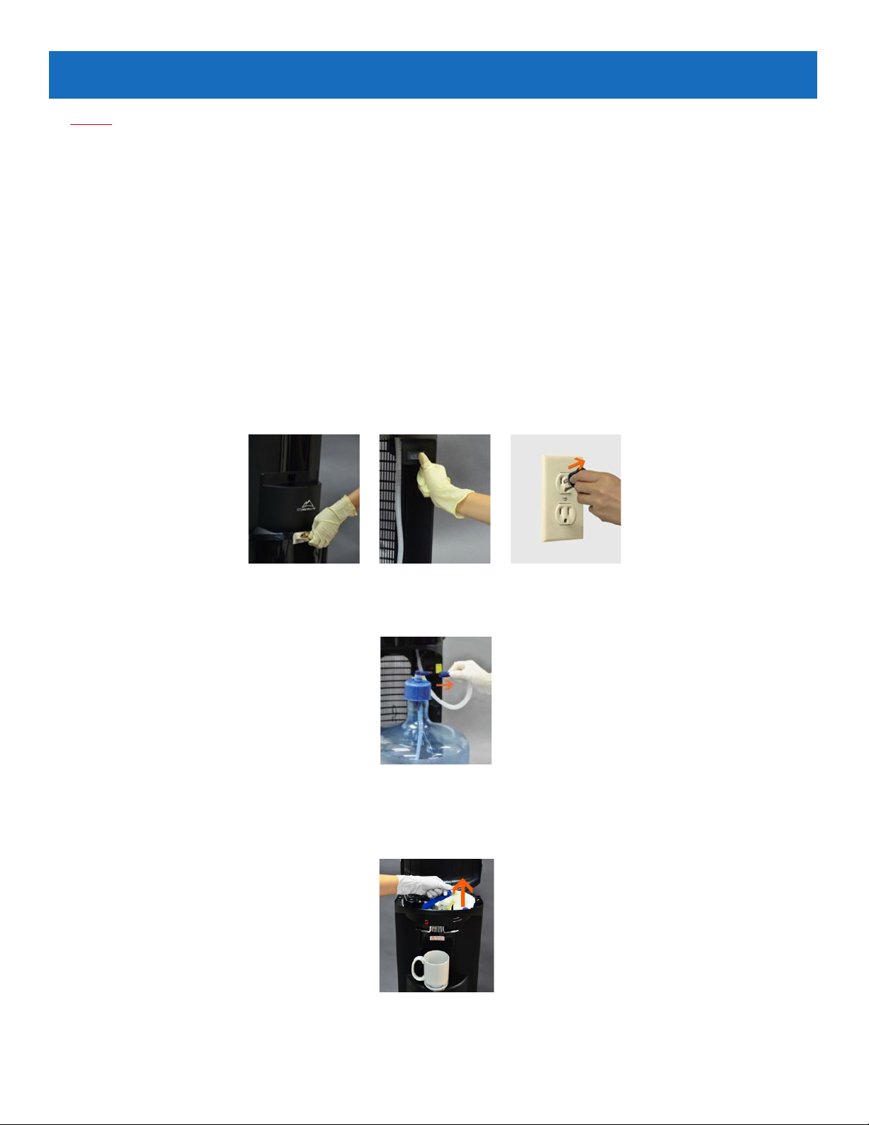
6. Remove the red protective cap from the blue tube of the SmartFlo and install onto the bottle adapter assembly
(Fig. 7).
7. Slide bottle into cabinet (Fig. 8) and close the door. Push down to close.
8. Depress the cold lever to fill the cold water tank (Fig. 9). When water begins to flow in a steady stream from the cold faucet,
the tank has been filled (approximately 1 minute although it may be less time). Repeat the process with the hot lever until the
flow out of the hot faucet is a steady stream. Lift the door to the bottle area and turn on the hot tank switch (Fig. 10) and
close the door by lowering back into place.
Fig. 7
Fig. 8
Fig. 10
Fig. 9

12
A blinking blue light above the cold water lever and a blinking “Replace Bottle” on the brew selection panel will alert you when
your water bottle is getting low. Water may be dispensed normally until empty (no water flows from the water outlets when lev-
ers are depressed).
Note: A flashing blue light above the cold water lever will alert you to when the SmartFlo Water Cartridge should be replaced.
The system has been pre-set to provide indication after a period of 12 months of use. User may operate the cooler as normal until
the bottle has been emptied. Note: To reset the life timer system, the SmartFlo is required to be removed from the dispenser for a
minimum of 15 seconds while the unit is connected to the mains power supply.
1. Open Dispenser door (Fig. 11). Slide door upward to access bottle area.
2. Slide empty bottle out of cabinet (Fig. 12).
3. Place a fresh bottle outside of the cabinet.
4. Clean the outside of new bottle with a cloth (Fig. 13). Remove the security label/seal from the bottle cap (if
applicable).
5. Remove bottle adaptor from the empty bottle (Fig.14) and remove the cap from the Hose Assembly (Fig.15).
Note: to maintain sanitization of the system, refrain from touching the section of the bottle adapter tube that
is inserted into the bottle.
Fig. 11
Fig. 12
Fig. 13
Fig. 14 Fig. 15
Changing the Water Bottle

13
6. Install Spike Cap through the bottle cap (do not remove bottle cap) and press down to secure (Fig. 16 & 17)
7. Insert the Bottle adaptor assembly through Spike cap until tube hits bottom of the bottle (Fig. 18 & 19).
8. Slide bottle into cabinet and close the door (Fig. 20 to Fig. 22). Push door down to close.
9. Place a container under faucet and dispense cold water until a smooth stream of water is dispensed. This may
take up to 1 minute.
Fig. 16 Fig. 17
Fig. 18
Fig. 20 Fig. 21 Fig. 22
Fig. 19
14
Notice:
The information and/or procedures presented in the following demonstration(s) should be performed by a trained Water Cooler
Service Technician only. Never attempt to service or repair a water cooler while it is plugged into any power supply. Prior to
any service or repair of the water cooler, ensure that the water has been completely drained from the system.
For the best tasting and highest quality water, it is recommended to change the SmartFlo™ Water Cartridge every 12 months.
Follow the steps below to replace the SmartFlo™. It is recommended to empty the bottle prior to replacement of the SmartFlo™
and bottle adaptor.
Note: A blue light above the cold water lever will alert you when the SmartFlo™ Water Cartridge should be replaced. The sys-
tem has been pre-set to provide indication after a period of 12 months of use. Users may operate the cooler as normal until the
bottle has been emptied.
Note: To reset the timer system, the SmartFlo™ must be removed from the dispenser for a minimum of 15 seconds while the unit
is connected to the mains power supply.
1. Open Dispenser door (Fig. 1). Slide door upward to access bottle area. Turn off the hot tank power switch (Fig. 2) and unplug
the water cooler (Fig. 3).
CAUTION: WATER IN HOT TANK IS VERY HOT AND CAN CAUSE SEVERE BURNS. ALLOW SUFFICIENT TIME FOR
THE HOT WATER TO COOL BEFORE DRAINING (1-2 HOURS)
2. Take bottle out from the base. (Caution: don’t break the corrugated tube.) Remove the connecter from adapter. Fig. 4).
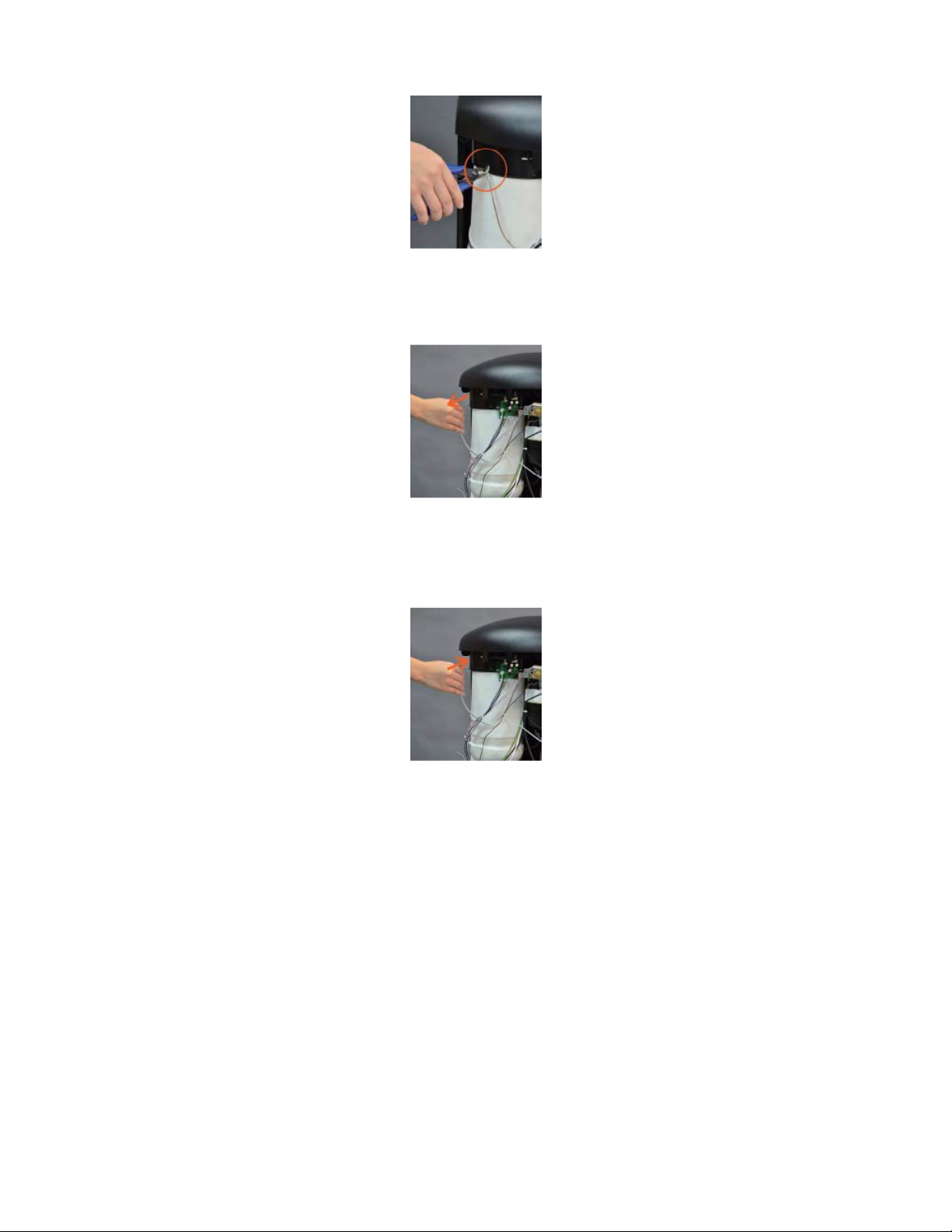
3. Place a glass or other container below the water outlets (to catch drips) and unlatch the blue locking clip located
near the front of the cooler to release the water tubing (Fig. 5).
Fig. 1 Fig. 2 Fig. 3
Fig. 4
Fig. 5
Replacing the SmartFlo™
15
Fig. 12 Fig. 13 Fig. 14
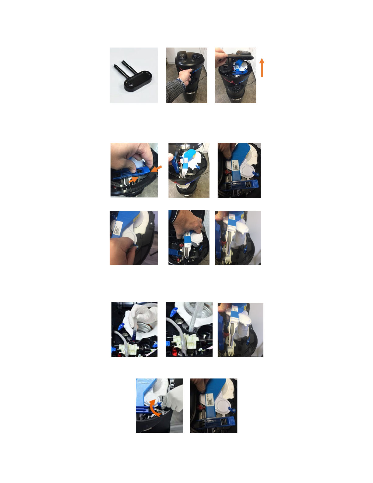
4. Using the top cover key (Fig. 6), insert into the two holes (on the front, approximately 2 inches above and to the right of
hot water safety button), push key inward to open top cover (Fig. 7 & 8).
5. Squeeze the latch’s end to open (Fig. 9 & 10). Turn counterclockwise to release the two blue knobs (Fig. 11 & 12).
Pull to remove the SmartFlo™ Water Cartridge and discard in recycling bin (Fig. 13 & 14).
6. Install a new SmartFlo™ Water Cartridge. Install the connector and corrugated tube into the inlet through cooler to bot-
tom (Fig. 15 & 16). Insert the reservoir into evaporator (Fig. 17). Ensure the SmartFlo™ is installed properly. Turn the
two blue knobs to lock into place (Fig. 18 & 19).
Fig.11
Fig. 9 Fig. 10
Fig. 6 Fig. 7 Fig. 8
Fig. 15 Fig. 16 Fig. 17
Fig. 18 Fig. 19
16
Fig. 20
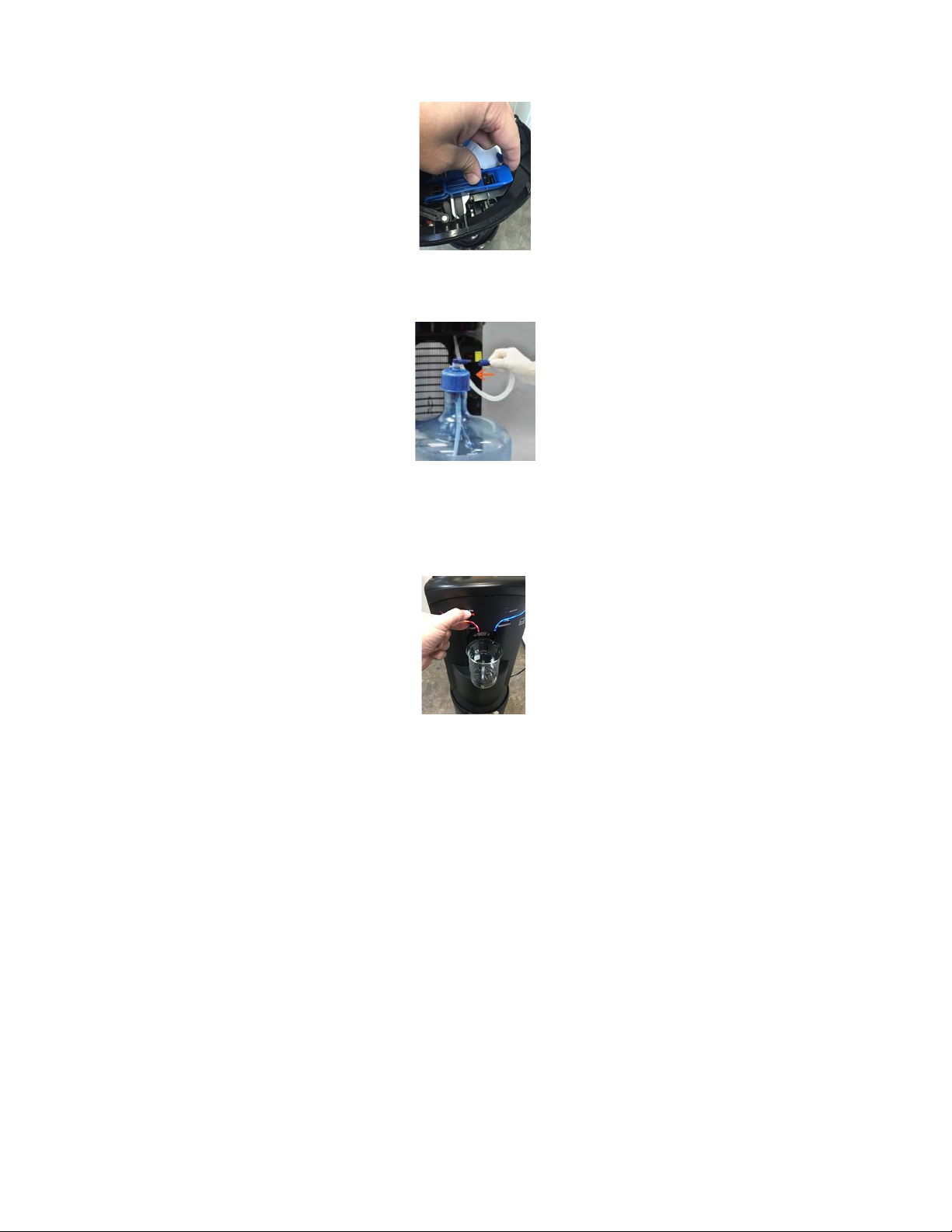
7. Close and latch the locking arm (Fig. 20).
8. Install the hose connecter to bottle adapter (Fig. 21). Put the water bottle into the bottom of the cooler.
9. Close the top cover and lower the door to close. Plug the cooler into the electrical outlet. Pull the cold faucet lever
until a steady stream of water comes out. Then, push the hot safety button and press the hot water faucet lever to
activate water flow. Keep pressing the hot water faucet lever until water comes out (Fig. 22).
10. Lift the door to open. Turn the hot tank power switch ON. Push downward to close the door.
CAUTION: TO PREVENT DAMAGE TO THE HOT TANK, DO NOT SWITCH ON IF HOT TANK IS EMPTY.
Fig. 21
Fig. 22

17
Fig. 1
Notice:
The information and/or procedures presented in the following demonstration(s) should be performed by a
trained Water Cooler Service Technician only.
Never attempt to service or repair a water cooler while it is plugged into any power supply.
Prior to any service or repair of the water cooler, ensure that the water has been completely drained from the system.
1. Turn off hot tank power switch (located on the front panel, inside the door) (Fig. 1) and unplug the water cooler.
2. Remove the upper back panel from the water cooler.
3. Remove both mounting screws from the cold control. (Fig. 2 & 3).
4. Remove the cold control from the plastic shelf (Fig. 4).
5. Remove the terminals from the thermostat, taking care to identify where each terminal is installed (Fig. 5 - 7).
Fig. 2 Fig. 3
Fig. 5 Fig. 6 Fig. 7
Fig. 4
Cold Control Replacement
18
6. Cut the small plastic zip tie holding the cold control sensor bulb to the evaporator insulation (Fig. 8).
7. Pull the sensor tube out from the evaporator insulation to remove (Fig. 9). Note: If required, install the Sensor tube cover onto
the replacement cold control.
8. Install the replacement cold control into the evaporator insulation until it bottoms out—approximately 5 inches (Fig. 10). Note:
Care should be taken while installing the sensor tube that the protective cover within the evaporator insulation is in the proper
position.
8. Install a replacement zip tie to hold the sensor within the evaporator insulation.
9. Reinstall the wire terminals onto the cold control taking care to place in original position.
10. Install the cold control to the plastic shelf, re-using the original screws.
11. Reinstall the upper back panel.
12. Re-connect the cooler to the power supply. Note: Ensure proper thermostat setting (see section for Cold Control Adjustment).
Fig. 8
Fig. 9
Fig. 10
19
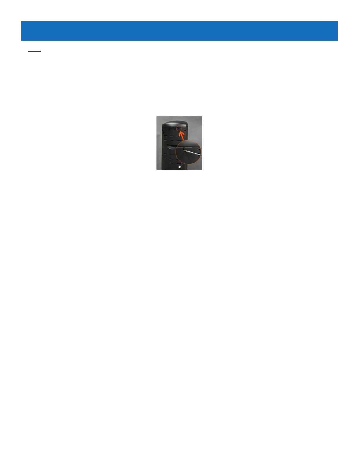
Note:
The Cold Control can be adjusted without the removal of any panel. The adjustment screw is on the top rear (when viewed
from the rear, see Fig. 1).
To make the water colder, rotate the screw in the clockwise direction approximately 1 hour position. Allow the cooler to
stabilize for 2-3 hours to ensure proper temperature of the cold water. (Note: do not change the setting by more than 1 hour
setting at a time to prevent freezing).
To make the water warmer, rotate the screw in the counterclockwise direction approximately 1 hour position. Allow the
cooler to stabilize for 2-3 hours to ensure the proper temperature of the cold water.
Fig. 1
Cold Control Adjustment

20
Notice:
The information and/or procedures presented in the following demonstration(s) should be performed by a trained Water Cooler
Service Technician only.
Never attempt to service or repair a water cooler while it is plugged into any power supply.
Prior to any service or repair of the water cooler, ensure that the water has been completely drained from the system.
Note: Begin with the unit unplugged, the water drained, and the upper back panel removed.
Tip: Use a plier or flathead screwdriver to pry wire connecters off (Fig. 1).
1. Remove the wire terminals from the thermostat or limiter and identify.
2. Remove the two screws. Remove the thermostat (or limiter) from its bracket (Fig. 2).
3. There is enough heat transfer paste on the tank and old control to simply wipe the bottom of the new con-
trol against the old one (Fig. 3). Place into position and evenly tighten the two screws.
4. Reconnect the wires onto the thermostat (or limiter) as identified.
Fig. 3
Fig. 2
Fig. 1
Thermostat and/or Limiter Replacement
Other manuals for Storm Cafe
1
Table of contents


