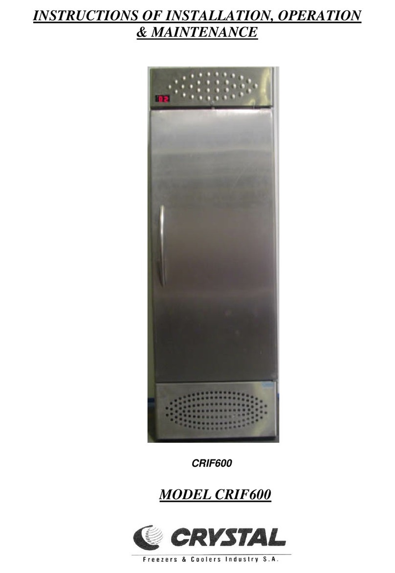
Crystal CRF400 Programming manual

INSTRUCTIONS OF INSTALLATION, OPERATION
& MAINTENANCE
VERTICAL STATIC DISPLAY FREEZERS CRF400

2
1. INTRODUCTION
Proper installation and maintenance are essential for maximum satisfaction from your appliance. It is therefore
necessary to carefully read and observe the indications of these instructions for use.
2. TRANSPORT (figure 1)
3. INSTALLATION OF THE APPLIANCE
Unpack the appliance. In order to remove it from the pallet use a screwdriver and unscrew the 4 screws that are
given in figure 2.
Make sure the appliance is stable and in horizontal position.
Perfectly level the appliance by adjusting the adjustable stands that are provided with the appliance.
Never install the refrigerator in a room exposed to direct sun radiation nor in the vicinity of a heat source
such as cooker, a stove, a heater, a fireplace etc.
Avoid installing the appliance in confined rooms, damp, and without airing or in wall recesses.
The clearance behind the appliance must be at least 10 cm distance from the wall or other voluminous objects.
This clearance is the minimum required to ensure normal ventilation of the refrigeration mechanism. You will
find one spacer with two fixing screws within the appliance which obtains the airing space of 10 cm in the case of
screwing it directly on the grill panel of the engine-room (see figure 3).
4. ELECTRICAL CONNECTION
Make sure that the feed cable and the socket are appropriate for the appliance power. In case of doubt, contact a
qualified technician.
Before inserting the plug in the mains outlet, make sure the voltage mentioned on the nameplate inside the appliance
to the right, compiles with the one of your network. A discrepancy of +/- 10% is acceptable.
Too high or too low voltage network may seriously damage the compressor. Such damages are not covered by the
guarantee. The appliance must be earthed as prescribed by the relevant legislation whereas it is indispensable for your
personal safety. The manufacturer has provided for earthing in the electrical installation and external surface of the
appliance.
NOTE: Upon start up, running may be noisy. Noise will only last for the engine “running in” time and will dim
progressively.
Figure 1
Always transport the appliance in vertical position, do not
overturn it and do not load it in leaning position.
Figure 2 Figure 3
SCREW
SCREW
SCREW
Figure 2

3
5. OPERATION
Once the appliance is installed, wait for at least 30 minutes before start – up. Afterwards, insert the plug in the mains
outlet.
The thermostat and the operation switch “I-0” are located behind the fitted metallic grill panel. In order to operate the
appliance, the operation switch must be on position “I” and the thermostat should be switched on the appropriate setting
(not on ‘0’, see figure 4&6).
Start up the appliance with no load and make sure the door is properly closed.
Wait for at least two hours so that the required temperature is achieved inside the freezer.
Store the products.
The compressor will not restart immediately, in case of starting up the appliance straight after terminating its
operation – either via the thermostat or due to power failure –. This is normal. The compressor will automatically start
soon after.
For your appliance’s protection, always wait for fifteen minutes before each restart.
After each opening the door, for a short while, you will notice some mist on the window. This is absolutely normal
and the mist will disappear completely.
Do not use electrical devices inside the food storage area of the appliance.
WARNING: we remind you that your appliance is a preserver for frozen products. It has not been designed
for the storage of products of ambient or higher temperature.
This appliance is not designed for use from the people (including children) with decreased physical , aesthetic or
intellectual abilities or with deficiency of experience and knowledge, unless they are under supervision or have been
given instructions concerning the appliance use from the person responsible for their safety.
The children have to be supervised in order to avoid playing with the device.
6. THERMOSTAT (Figure 4)
The thermostat, which is located behind the fitted metallic grill panel automatically sets the temperature inside the
appliance so that it varies from the minimum to the maximum value permitted by the chosen setting.
The thermostat position is set and checked by our company to ensure the optimum preservation temperature of products,
such as ice-cream cakes, ice creams and etc.
7. THERMOMETER
The cylindrical thermometer, which is located behind the fitted metallic grill panel that covers the engine-room
located in the appliance’s base, indicates the temperature inside the food compartment.
8. LIGHT SWITCH
The light switch, which is located behind the fitted metallic grill panel beside the thermometer, features two positions
ON – OFF and controls the internal lighting as well as the lighting of the advertising sign placed at the top of the
appliance.
The thermostat, depending on the ambient temperature and its design
classification, is capable of maintaining the products to an average
temperature from –18 to -23οC. Lower temperatures can be achieved
inside the appliance when the thermostat adjustment switch is rotated
clockwise from position 1 to position 7.
When the thermostat is set to 0 (off) the appliance is switched off.
Figure 4

4
9. WATER DRAINING
Condensation waters, which come from the evaporator and from the evaporative shelves of the refrigeration cabin
during defrosting, drain as follows:
•Set the operation switch on position 0 (figure 5-A)
•Unscrew the screw that is located at the top of the metallic grill panel (that covers the engine-room) and
holds it on the metallic support of the thermometer (top-left of the appliance). Next, remove the fitted
grill panel, moving it slightly upwards so that it disengages from the screws and then pull it towards
yourself.
•Pull the drainage towards you (see the figure 5-B).
•Place a container beneath the drainage pipe for collecting the water (see the figure 5-B).
•Remove the outer plug pulling it gently (see the figure 5-B)
•Remove the grill panel which is located at the bottom of the freezer (from inside the cabin).
•Remove the inner drainage plug that is located on the freezer’s bottom inside the cabin.
•Once the waters are drained, repeat the steps in the inverse order and start operating the appliance by
setting the operation switch on position I.
10. CLEANING OF THE FREEZER
For the purpose of cleaning the freezer interior, DO NOT use sharp objects or chemicals in order to accelerate the
process of defrosting. Follow the instruction that is recommended by the manufacturer, i.e. the use of lather in lukewarm
water.
11. CLEANING OF THE CONDENSER (figure 6)
For proper operation of the appliance, the condenser must be free of dust. Clean the condenser at least once in
three months, as follows:
Unplug the appliance.
Remove the metallic grill panel from the appliance following the instructions in paragraph 9.
Clean the condenser by using a soft brush or a vacuum cleaner.
Replace the grill panel back on the holding screws.
Insert the plug and switch on the appliance.
LIGHT
SWITCH
THERMOMETER OPERATION
SWITCH
THERMOSTAT
INNER
DRAINAGE PLUG
OUTER DRAINAGE
PLUG
DRAINAGE
PIPE
OUTER
DRAINAGE PLUG
WASTE WATER
COLLECTION CONTAINER
Figure 6
Figure 5-B
Figure 5-A

5
12. SERVICE
A) If the appliance does not work satisfactory or at all, check as follows:
The temperature inside the appliance is not cool enough, check whether:
¾The appliance is in the vicinity of a heat source and thus should be moved.
¾The condenser is covered with dust and dirt and should be cleaned.
¾The thermostat is on a lower setting (i.e. position ‘1’ or ‘2’) and not on the recommended one (i.e. half-way,
position 4).
¾The door of the appliance is properly closed.
Although connected, the appliance does not work, check whether:
¾There is power in the socket and the plug is properly inserted in the socket.
¾There is power supply network failure.
¾The power control fuse to your appliance has been destroyed.
¾Your appliance’s power cable is damaged.
Your appliance emits a metal noise, check whether:
¾There is contact between your appliance and other metallic objects.
¾The appliance is properly leveled with the floor.
B) If you wish to replace the lamp or the advertising sign on the upper part of your appliance do that as follows:
Unplug the appliance.
Unscrew the screw located halfway on the upper part of the advertising sign and unbutton the sign by pressing it
slightly upwards.
Replace the lamp and repeat the steps in the inverse order so that your appliance gets back in operation.
C) If you wish to change the lamp in the interior (figures 7 & 8) do that as follows:
Unplug the appliance.
By using a screw driver press slightly the edge of the transparent fitted cover so that it comes out. Then pull both
the edges of the cover so that the compartment is completely released from the cabin (figure 7).
Disconnect the lamp holder (figure 8-3) from the lamp (figure 8-2) without removing the lamp and then remove it
from the metal holders (figure 8-1).
Replace the lamp and repeat the steps in the inverse order so that the appliance goes back in order.
TRANSPARENT
FITTED COVER
Figure 7
Figure 8

6
D) If the door does not close satisfactory (does not revert or does not secure properly) you may proceed as follows:
E) In case that a service must take place in the compartment of the engine, note that it is necessary to be done by a
qualified technician and proceed as follows:
Remove the metal grill panel from the appliance following the instructions in paragraph 9.
Unscrew the two screws that hold the sliding engine base, which are located at the front, just behind the grill panel.
Pull towards you the engine base without moving the appliance.
Proceed to the service of the engine.
After you have finished, repeat the steps in the inverse order so that your appliance gets back in operation.
F) If the feed cable is damaged, it must be replaced by the manufacturer or a qualified person from the service
department, or by similarly specialized personnel, in order to avoid danger.
G) Do not cause any damage to the cooling circuit by the intervention of unauthorized personnel. Advise the
manufacturer and assign such works only to specialized technicians.
NOTE: Our Company has an organized network of qualified technicians throughout Greece. For any maintenance
or operation problem, contact your retailer.
Keep this booklet as well as all documents provided with your appliance and read the guarantee terms carefully.
Place a sharp object - such as a small screw driver, stabber,
nail etc - in one of the holes which are located at the top of
the torsion bar, which is located on the upper side of the door
under the top hinge.
By applying resistance with the stabber, unscrew with the
screwdriver the kingpin which is screwed on the top of the
torsion bar (figure 9). ATTENTION, HOLD THE SHARP
OBJECT STEADY TO AVOID AN INJURY BECAUSE
THE SPRING IS UNDER TENSION.
By using a sharp object, turn the top of the torsion bar
anticlockwise until you are able to screw promptly the
kingpin in the next hole. After you screw the kingpin remove
the sharp object.
Examine if the door secures satisfactorily following the above
mentioned procedure. If not, repeat the above steps.
TOP OF
TORSION BAR
DOOR
SHARP
TOOL
CANOPY
KINGPIN
SCREW
DRIVER
HINGE
Figure 9

7
1Fluorescent
Lamp
Λαµπτήρας
φθορισµού
Στραγγαλιστικό
πηνίο
Μετασχηµατιστής
πόρτας
Illuminated
canopy
Light
switch
glass
resistor
Door
Internal
lighting
Overload
Start
capasitor
Relay
Terminal
Door
Transformer
Operation
Switch
Thermostat
Condenser
fan motor
Ballast
Starter
ΦΑΣΗ- LINE
ΤΥΠΟΣ ΚΑΛΩ∆ΙΩΝ
CABBLE 'S TYPE
ΓΕΙΩΣΗ - GROUNDING
ΟΥ∆ΕΤΕΡΟΣ - NEUTRO
12
Yw-gn Μετώπη
διαφήµισης
∆ιακόπτης
φωτισµού
16
15
Αντιστάσεις
τζαµιού
Πόρτα
καταψύκτη
13
14
Εσωτερικός
φωτισµός
Yw-gn
We
Be
'Ασπρο - White
Μπλε - Blue
Κίτρινο - Yellow
πράσινο - green
Bn
Re
ΧΡΩΜΑ ΚΑΛΩ∆ΙΩΝ
CABBLE 'S COLOUR
Καφέ - Brown
Μαύρο - Black
Κόκκινο - Red
Bk
Yw-gn
Re
4 3
9Θερµικό
11
10
Πυκνωτής
εκκίνησης
Ρελέ
8Κλέµα
7
Be Bn
4∆ιακόπτης
λειτουργίας
6
5
Θερµοστάτης
Ανεµιστήρας
συµπυκνωτή
3
2
Εκκινητής
6
Be
L1N
Bk
5
Bk
Yw
Be
Bn
10
Be
Bn
Be
Bn
11
S
C
Bk
R
Bk
Bn Bn
N
NBe
L
8
LBn
Yw-gn
S
1
S
We We
3
We
We
2
14
Bn
2
N
L
We
Bn
Be
Bn
Be
S
3
We 1
Yw-gn
16 Bk
7
Bk
12
13
15
13. ΗΛΕΚΤΡΟΛΟΓΙΚΟ ΚΥΚΛΩΜΑ (ELECTRICAL CIRCUIT)
4
9
MONTEΛΟ (MODEL) : CRF400
Table of contents
Other Crystal Freezer manuals
