Crystal CRIF600 Programming manual

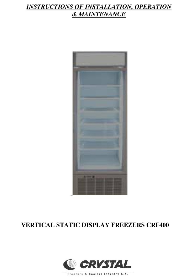
INSTRUCTIONS OF INSTALLATION, OPERATION
& MAINTENANCE
CRIF600
MODEL CRIF600

2
1. INTRODUCTION
Proper installation and maintenance are essential for best use of your appliance. It is therefore necessary to
carefully read the instructions of this manual.
2. TRANSPORT (Figure 1)
3. INSTALLATION OF THE APPLIANCE
•Unpack the appliance. In order to remove it from the pallet use a screwdriver and unscrew the 4 screws (Fig. 2).
•Make sure that the appliance is stable and in horizontal position.
•Perfectly level the appliance by adjusting the adjustable stands that are provided with the appliance.
•Never install the freezer in a room exposed to direct sun radiation nor in the vicinity of a heat source such as
cooker, stove, heater, fireplace etc.
•Avoid installing the appliance in confined rooms, in rooms with dampness without airing or in wall recesses.
•The clearance behind the appliance must be at least 10 cm distance from the wall or other voluminous objects. This
clearance is the minimum required to ensure normal ventilation of the refrigeration mechanism. You will find one
spacer with two fixing screws within the appliance, which obtains the airing space of 10 cm after fitting it at the
back of the freezer (Fig. 3A).
•Inside your appliance, you will find:
1. Inox door handle and two inox screws inside a plastic bag.
2. Offset handle and two stabilization screws inside a transparent bag.
3. Shelves for products placement.
4. Four hooks per each shelf for its proper stabilization. (see figure 3).
5. One pair of keys for the lock (see figure 1a).
4. ELECTRICAL CONNECTION Figure 1a
Make sure that the feed cable and the socket are appropriate for the appliance’s power. In case of doubt, contact a
qualified technician.
Before inserting the plug in the mains outlet, make sure the voltage mentioned on the nameplate inside the appliance
(on the top right) compiles with the one of your network. A discrepancy of +/- 10% is acceptable.
Too high or too low voltage network may seriously damage the compressor. Such damages are not covered by the
guarantee. The appliance must be earthed as prescribed by the relevant legislation whereas it is indispensable for your
personal safety. The manufacturer has provided for earthing in the electrical installation and external surface of the
appliance.
NOTE: Upon start up, running may be noisy. Noise will only last for the engine “running in” time and will
decrease progressively.
5. SHELVES (Figure 3).
Place the shelves upon the hooks carefully so that the two
fitted wires of each shelf to be placed at the cabinet’s back (Fig 3).
That way, the proper airflow at the cabinet’s back is ensured.
Figure 1
Always transport the appliance in vertical position, do not
overturn it and do not load it in leaning position.
SCREW
SCREW SCREW
Figure 2
Β
Α
Figure 3

3
6. OPERATION
Once the appliance is installed, wait for at least 30 minutes before start – up. Afterwards, plug in the appliance.
The thermostat and the operation switch “O/I” are located behind the fitted metallic grill panel. In order to operate the
appliance, the operation switch must be on.
Start up the appliance with no load and make sure the door is properly closed.
Wait for at least two hours in order to achieve the required temperature inside the freezer. Then, place the products.
The compressor will not restart immediately, in case of starting up the appliance straight after terminating its operation –
either via the thermostat or due to power failure –. This is normal. The compressor will automatically start soon after.
For your appliance’s protection, always wait for fifteen minutes before each restart.
Do not use any electrical devices inside the storage places for appliance’s foods.
Keep the air openings in the cover without any obstacle.
This appliance is not to be used by individuals (and kids also) with low physical or mental abilities or lack of
experience and knowledge but only if they are supervised or specific orders were given by someone who is responsible
for their safety.
The kids should be supervised in order to avoid playing with the appliance.
7. PRODUCTS LOADING (Figure 4)
8. ELECTRICAL THERMOSTAT - THERMOMETER (Figure 5)
Place the products on the shelves without blocking the proper
airflow inside the cabinet (Fig. 4). Do not place products at the top
shelf, which would block the airflow exit due to their height, from the
fan to the cabinet top. The distance of 10 cm among the products and
the fan is necessary.
The thermostat is located behind the fitted metallic canopy at
the top of the freezer. Our company sets it so that your appliance
could be able to maintain your products to an average temperature
from -24 to -18οC according to its climate class (40 οC temperature
and 40% relative humidity of the environment).
If you wish, you can change the temperature average inside
the cabinet by programming the electrical thermostat-thermometer
properly.
The necessary commands are given below.
1
Í
1
Í
Figure 4
Figure 5

4
The thermostat is been set by our company to ensure average temperature
from -24 οC (lower set point, stops the compressor’s operation) to -18 οC (higher set point, starts the compressor’s
operation). You can change the lower set point easily as follows:
By pressing the i-set button, press the same time the left arrow (temperature reduction) or the right arrow (temperature
increase). That way, you can change the lower set point according to your needs (Fig. 5).
For example, if you set a new set point at -23 οC, then the new temperature average will be from -23 to -17 οC.
The electrical thermostat-thermometer has been set by our company so that the lower set point to have an average
between -30 to -15 οC. The average between the lower and the higher set point is fixed and equal to 6οC.
In case of freezer malfunction, some alarms warnings are given on the display through explicit indications and
intermittent buzzer sounding. During an alarm, by pressing any button, the buzzer is muted.
If the problem remains (is not repaired), the buzzer sounding will be repeated for 20 second per hour while the
digital indication will be always shown on the display.
Digital Indications of ALARMS
INDICATION EXPLANATION POSSIBLE CAUSE POSSIBLE SOLUTION
1.HI ….. High cabinet temperature Ice forming upon evaporator/
ambient temperature too
high/ bad air flow due to
products positions.
Defrost/improve ambient
climate conditions/
products re-arrangement,
see §7
2.LO ….. Low cabinet temperature Thermostat damage Replacement
3.DO ….. Door left open … Close it at once
4.HP ….. High condenser pressure Dust upon condenser Condenser Cleaning (See
§11)
5.E1 ….. False indication of cabinet sensor …. Replacement
6.E2 ….. False indication of evaporator sensor … Replacement
7.E3 ….. False indication of condenser sensor … Replacement
In any case, you should be advised by the manufacturer and assign such works only to specialized technicians.
Additionally:
¾Whenever the freezer’s door is open, the evaporator fan located at the top of the cabinet will stop.
¾If the freezer’s door left open for 3 minutes, the compressor will stop.
¾If the freezer’s door left open for 5 minutes, then the corresponding indication ALARM will appear on the
thermostat.
Defrost procedure
The thermostat has been set by our company to perform 3 defrost circles per 24 hours using an electrical resistor for
15 minutes each time. During defrost operation, the evaporator’s fan stops.
The defrost procedure is programmed to last 15 minutes maximum in case of having evaporator’s temperature less
than 30 οC. If during this procedure, the evaporator’s temperature overpasses the limit of 30 οC, the defrost procedure will
end immediately (will not last for 15 minutes).
After the defrost procedure, two cycles will follow:
1. The freezer remains for 4 minutes in order the water drainage to be completed through the plastic tube
from the evaporator to the engine room.
2. Once the drainage is completed, the freezer remains for another 4 minutes so that the temperature of -10 οC
to be achieved inside the evaporator. Then, the evaporator fan will start its operation. If during this last 4
minutes procedure, the limit of -10 οC inside the evaporator is not achieved, the evaporator fan will start
anyway. In case of achieving the limit of -10 οC before the end of the 4 minutes, the evaporator fan will
also start.

5
You could also start defrost manually by pressing the defrost button (the one with the defrost sign) for at least 2
sec.
Finally, during freezer’s operation, the freeze indication is ON (top right side of the thermostat) while there is an
indication that the evaporator fan works too (indication below the previous one). Every time that the freezer’s door is
open, the evaporator’s fan stops and the indication of the evaporator’s fan is OFF.
During defrost procedure, the defrost indication (located below the other indications) is ON while the other
indications (freeze and evaporator’s fan) are OFF.
For more information regarding the instructions of use of the electronic thermostat-thermometer, you could be
advised by its manufacturer’s manual.
9. WATER DRAINAGE
Condensation waters, which come from the evaporator at the top of the cabinet, are drained externally through a
plastic tube and gathered inside a plastic container, which is located inside the engine room.
10. CLEANING OF THE FREEZER
For the purpose of cleaning the freezer interior, DO NOT use sharp objects or chemicals in order to accelerate the
defrost process. It is recommended the use of lather in lukewarm water.
11. CLEANING OF THE CONDENSER (Figure 6)
For proper operation of the appliance, the condenser must be free of dust. Clean the condenser at least once
in a month, if your appliance operates in an outdoor environment, or once in three months, if it operates indoors,
as follows:
•Unplug the appliance.
•Unscrew the screw that is located at the top of the metallic grill panel (that covers the engine-room) at the bottom of
the appliance. Next, remove the fitted grill panel, moving it slightly upwards so that it disengages from the screws
and then pull it towards yourself.
•Clean the condenser by using a soft brush or a vacuum cleaner (Fig. 6).
•Re-place the metallic grill panel in the inverse order.
•Insert the plug in the mains and switch on the appliance.
Figure 6

6
12. SERVICE
A) If the appliance does not work satisfactory or at all, check as follows:
The temperature inside the appliance is not cool enough, check whether:
¾The appliance is in the vicinity of a heat source and thus should be moved.
¾The condenser is covered with dust and dirt and should be cleaned.
¾The settings of the electrical thermostat-thermometer have been changed.
¾The door of the appliance is not properly closed.
¾The products are placed recently and the appliance needs more time to achieve the desirable temperature inside
the cabinet.
Although connected, the appliance does not work, check whether:
¾There is power in the socket and the plug is properly inserted in the socket.
¾There is power supply network failure.
¾The power control fuse to your appliance has been destroyed.
¾Your appliance’s power cable is damaged.
Your appliance emits a metal noise, check whether:
¾There is contact between your appliance and other metallic objects.
¾The appliance is properly leveled on the floor.
B) If the door does not close satisfactory (does not revert or does not secure properly) you may proceed as follows:
C) In case that a service must take place in the compartment of the engine, note that it is necessary to be done by a
qualified technician and proceed as follows:
Remove the metal grill panel from the appliance following the instructions in paragraph 11.
Unscrew the two screws that hold the sliding engine base, which are located at the front, just behind the grill panel.
Pull towards you the engine base without moving the appliance.
Proceed to the service of the engine.
After you have finished, repeat the steps in the inverse order so that your appliance gets back in operation.
D) If the power cable is damaged, the manufacturer must replace it or a qualified person from the service department,
or by similarly specialized personnel, in order to avoid danger.
E) Do not cause any damage to the cooling circuit by the intervention of unauthorized personnel. Advise the
manufacturer and assign such works only to specialized technicians.
Keep this booklet as well as all documents provided with your appliance.
Place a sharp object - such as a small screw driver, stabber, nail
etc - in one of the holes which are located at the top of the torsion
bar, which is located on the upper side of the door under the top
hinge.
By applying resistance with the stabber, unscrew with the
screwdriver the kingpin which is screwed on the top of the torsion
bar (Fig. 7). ATTENTION, HOLD THE SHARP OBJECT
STEADY TO AVOID AN INJURY BECAUSE THE SPRING
IS UNDER TENSION.
By using a sharp object, turn the top of the torsion bar
anticlockwise until you are able to screw promptly the kingpin in
the next hole. After you screw the kingpin remove the sharp
object.
Examine if the door secures satisfactorily following the above-
mentioned procedure. If not, repeat the above steps.
TOP OF
TORSION BAR
DOOR
SHARP
TOOL
CANOPY
KINGPIN
SCREW
DRIVER
HINGE
Figure 7

7
Table of contents
Other Crystal Freezer manuals
