- 10 -
w w w . C T C U . c o m
Operation
Select any of the menu items by keying in the menu item number or letter.
Use the [ESC] to return to a previous menu. Any setting is immediately
applied to the transponder's circuitry. After all of the parameter settings
have been selected, press "s" from the main menu to save the parameters
in non-volatile RAM (NVR). To revert to previous settings before saving,
press "r" to reset (reload previously saved parameters).
Explanation of Settings
1. Port Active: This will enable or disable the card. When inactive, no
transmissions will be able to occur.
2. Baud Rate Select: This will bring up the data rate selection list. Select
the required 3R recovery speed by choosing the protocol.
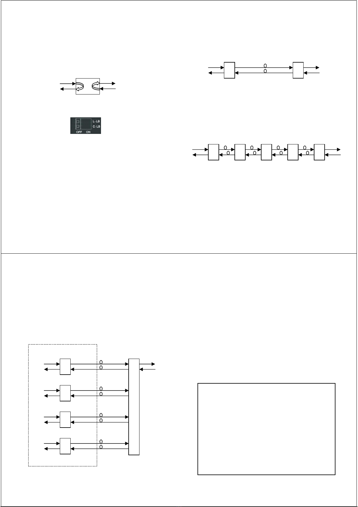
3. Loopback Function: Regardless of settings for items 4&5, if disabled all
loopback functions are terminated.
4. Line Side Loopback: This will activate the Line side loop back
diagnostics. Item 3 must also be enabled.
5. Client Side Loopback: This will activate Client side fiber loop back
diagnostics. Item 3 must also be enabled.
6. Line Side Link Fault Pass-Through: Enables or Disables LFP function.
7. Client Side Link Fault Pass-Through: Enables or Disables LFP
function.
8. Line Side Auto Laser Shutdown: This can enable ALS for line side.
9. Client Side Auto Laser Shutdown: Can enable Client side ALS.
D. XFP/SFP+ Digital Diagnostic: Enables user to read the serial data
stored in XFP/SFP+ modules.
F. Factory Default: Restores all settings to factory default.
R. Port Reset: This will cause the parameters settings in NVR to be
reloaded.
S. Store Parameters: Saves the setting parameters into non-volatile RAM
(NVR)
- 11 -
w w w . C T C U . c o m
Modern optical SFP transceivers support digital diagnostics monitoring
(DDM) functions according to the industry-standard SFF-8472. This feature
is also known as digital optical monitoring (DOM) and gives the end user
the ability to monitor real-time parameters of the SFP, such as optical
output power, optical input power, temperature, etc.
Example of reading Digital Diagnostics in XFP
Parameters are read from any MSA (Multisource Agreement) compliant
XFP/SFP+ module. Extended information is only available in modules which
support D/D or DOM function.
****************************************
*** CTC UNION TECHNOLOGIES CO.,LTD ***
*** FRM220-10G Manager Ver:1.00 ***
****************************************
XFP/SFP+ Digital Diagnostic
<1> Line Side Digital Diagnostic: [Have]
<2> Client Side Digital Diagnostic: [Have]
--------------------------------------------------------------
----------------
Line Side:
Vendor Name :[FINISAR CORP. ]
Vendor Part Number :[FTLX8511D3 ]
Fiber Type :[Multi ]
Tx Wave Length :[0850 nm ]
RX Wave Length :[0850 nm ]
Link Length :[0082 m ]
Tx Power :[ -03 dBm]
Rx Power :[ -13 dBm]
Rx Sensitivity :[ 00 dBm]
Temperature :[ 42 C ]
- 12 -
w w w . C T C U . c o m
Upgrading
The FRM220-10G card may be firmware upgraded when it is placed in
the FRM220 with NMC management card. The user may use a local
console connection to the NMC, a remote Telnet (IP) connection, or a Web
based (HTTP) connection with any available browser. The NMC
communicates to all cards through a serial RS485 control bus. The upgrade
code is transferred to the NMC by way of TFTP server.
Quick Procedure
Place the line card's upgrade code on the TFTP server. Make sure you
know the case sensitive file name. Connect to the FRM220-NMC by local
console or by remote Telnet connection. From the main menu choose:
<L> SNMP System Configuration Setup
Then:
<U> Upgrade Line Card Menu
Select the line card type (3R-10G) and local unit. Enter filename.
The upgrade should complete in only a couple of minutes. DO NOT
disconnect or pullout/insert any other cards during the upgrade process.
****************************************
*** CTC UNION TECHNOLOGIES CO., LTD. ***
*** FRM220 NMC VER. 2.01 ***
****************************************
<< Upgrade Line Card Menu >>
Target IP : 59.125.162.252
Target Gateway : 59.125.162.241
TFTP Server IP : 59.125.162.243
Please select a card type:
<1> : FRM220-10/100I and FMC-10/100I <3> : FRM220-SERIAL
<2> : FRM220-FXO/FXS <4> : FRM220-155MS
<5> : FRM220-DATAPORT <6> : FRM220-E1/T1
<7> : FRM220-1000EDS/1000ES-2F <8> : FRM220-1000ES-1/1000E-1/1000E-2F
<9> : FRM220-10/100IS-2 <A> : FRM220-1000TS/1000T
<B> : FRM220-3R-2.7G-2S/3S <C> : FRM220-5E1/ET100T
<D> : 5E1/ET100S <E> : E1/ET100T
<F> : E1/Data <G> : FRM220-3R-10G
<ESC>: Previous Menu
The card type = FRM220-3R-10G-SX
Please enter the slot number '2'~'20' or 'all': 3
The slot number = 3
Please select <1>: Local <2>: Remote Unit <3>: Remote B Unit
<ESC>: Previous menu.
- 13 -
w w w . C T C U . c o m
About XFP/SFP+ Units
The FRM220-10G accepts any XFP or SFP+ unit that complies with the
MSA standard. Follow all ESD precautions when handling the card and
pluggable modules. Fiber optic components and cables are very sensitive to
dirt, dust and mishandling, especially in high-speed networks. Dirty or
mistreated fiber may cause errors and an unwanted degradation of signal
quality. Remove the dust caps on XFP/SFP+ only when ready to plug in
optical cables.
When selecting XFP/SFP+ optical modules, make sure the modules are
able to support the required data rates. A 10G XFP/SFP+ should be able to
support 10G Ethernet, OC-192/STM-64 or 10G Fiber Channel.
Installation
CTC Union supplied XFP/SFP+ modules are of the Bale Clasp type. The
bale clasp pluggable module has a bale clasp that secures the module into
the XFP/SFP+ cage.
•Inserting a Bale Clasp XFP/SFP+ Module into the cage
Step 1 Close the bale clasp upward before inserting the pluggable
module.
Step 2 Line up the XFP/SFP+ module with the port, and slide it into the
cage.
•Removing a Bale Clasp XFP/SFP+ Module
Step 1 Open the bale clasp on the XFP/SFP+ module. Press the clasp
downward with your index finger.
Step 2 Grasp the XFP/SFP+ module between your thumb and index
finger and carefully remove it from the XFP/SFP+ cage.
Bale Clasp type SFP+ with bale open