CTI ComTec, Inc. PLA-800 User manual

Submitted by:
CTI.ComTec, Inc.
1 Classic Court, North
Palm Coast, Florida 32137
386-445-5545
March 16, 2002
CTI
.C
om
T
e
c
PLA
-800
Po
wer
A
m
plifi
er
S
er
ial
Nu
mb
er
1010
CTI
.C
om
T
e
c
PS
L
-
1000
Po
we
r
Su
pply
S
er
ial
Nu
mb
er
1010
T
e
s
t
R
e
por
t
f
or G
r
ant
of
C
er
ti
f
i
c
ation
Fo
r U
se
i
n
Par
t
97
A
mat
e
u
r
S
er
vi
ce
U
nd
e
r
T
h
e
R
ul
es
o
f
t
h
e F
e
d
er
al
C
o
m
mun
i
ca
t
ions
C
om
m
is
s
ion
PLA-800 USERS MANUAL
Appendix C

APPENDIX C
COPY OF SETUP AND OPERATING INSTRUCTIONS


Please Read Before Operating
Caution: Lethal High Voltage Present
Before operating both the PLA 800 and the PSL 1000, certain
precautions should be taken.
The PSL 1000 Power Supply generates over 2000 volts Direct Current at
a current capacity of over.6000 amperes. It also generates 350 Volts
Direct Current at .150 amperes. Both voltages are Lethaland will cause
death upon contact with the human body.
Although there are several built-in safety features to protect YOU from
exposure to high voltage, the following steps whould be followed at all
times.
NEVER OPERATE, EITHER THE PLA 800 OR PSL 1000, REMOVED
FROM THEIR INDIVIDUAL ENCLOSURES.
NEVER REMOVE ANY CONNECTORS FROM EITHER UNIT
WHILE POWER IS APPLIED.
NEVER INSERT METAL OBJECTS INTO THE COOLING VENT
HOLES ON TOP OR BELOW EITHER UNIT, WHILE POWER IS
APPLIED.
WARNING
THE VOLTAGES USED IN THIS EQUIPMENT ARE SUFFICIENTLY
HIGH TO ENDANGER LIFE. ALL PERSONNEL ARE ADVISED TO
BE THOROUGHLY FAMILIAR WITH THESE UNITS BEFORE
TROUBLESHOOTING THEM IN A POWER-ON CONDITION.
ALWAYS USE CAUTION.

INTRODUCTION
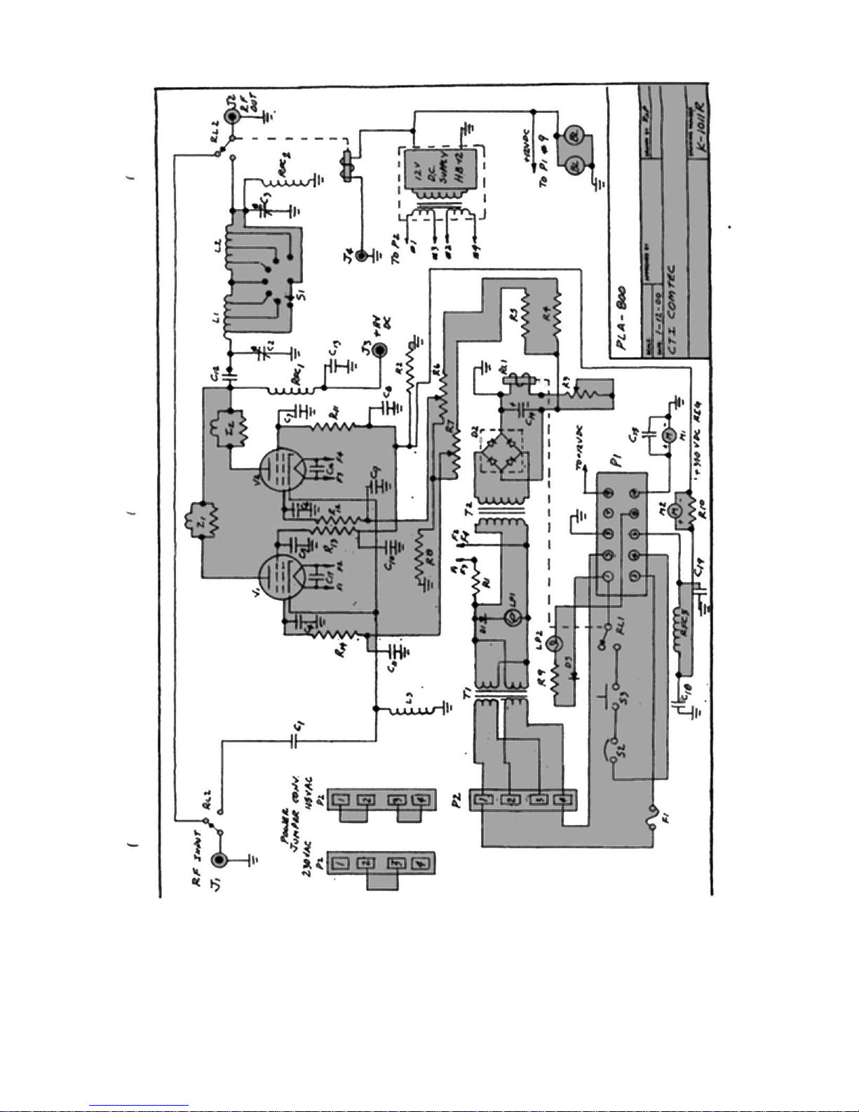
The PLA-800 Linear Amplifier uses a pair of 4CX250’s tetrodes as final amplifier tubes.
These tubes have been used and are still used today by the military because of its compact
size and ability to put out power ina compact space. They also have the ability to amplify
signal from .1 MHz to 500 MHz. Therefore their power bandwidth is approximately 500
MHz.
The 4CX250B’s have a control screen grid. The voltage and regulated current for the
screens are supplied by the PSL 1000 Power Supply. Using screen voltage regulation, the
grids have the advantage of self-limiting the current flow to the plates of the tubes. As a
result, the tubes cannot be driven into saturation causing distortion. The maximum
allowable screen current is regulated by the power supply. Once that point of current
demand is reached, the screen limits the plate current flow to it’s maximum. Therefore,
and ALC circuit, to prevent driver overload, is not required.
The maximum plate and cathode current flow is measured by the 0-500 ma. meter on the
front panel. The screen current only, is measured by the 0-50 ma. meter located also on the
front panel.
The band switch and plate and loading capacitors are also located on the front panel. The
capacitors use a 6:1 vernier ball drive to give smooth, easy tuning. Also located on the
front panel are the two lights indicating filament voltage on and plate current on. The
filament supply is contained in the PLA-800 and is protected by the 3 AG fuse next to the
indicator light. These bulbs are tungsten elements, with a life of 50,000 hours. The plate
on and off switch is located in the middle of both lamps.
Both the amplifier and power supply are inter-locked for your safety. The removal of the
FOUR (4) thumbscrews will allow you to slide the units forward and out of their respective
enclosures. NEVER open either unit with the AC and DC power applied. As an added
safety feature, the power supply has a mechanical shorting rod, which, upon sliding the
unit out of the enclosure beyond 1/4 of an inch, will ground the high voltage capacitor
bank. This is done for your safety and should NOT be defeated.
Built into the PSL 1000 power supply is a maximum current overload circuit. If more than
600 ma. is delivered to the load, the circuit will activate, opening the plate relay and
removing the high voltage. At the same time, the current overload indicator lamp on the
front panel of the power supply will light and an audible alarm will sound. To reset the
high voltage back, simply push the reset button on the panel. The power supply is also
equipped with a voltmeter allowing you to monitor the high voltage (0-500 vdc) and the
screen voltage (0-500 vdc).
Under normal loading conditions, the PLA-800 will deliver 600 watts key down or 1200
watts PEP output. However, the key down power level should not be maintained for more
than 10 seconds. In cases where RTTY or AM is used, the amplifier should be operated at
one-half power level. 1200 watts PEP can be operated at any time.

Tuning Procedure
On the rear panel of the PLA-800 you will see the Power Output Connector or RF Out
(SO239), a High Voltage connector, a Control Voltage Connector, a Push-to-Talk jack, a
Ground Connector, and the Power Input Connector (SO239) or RF In.
Connect the Control Voltage Connector and High Voltage Connector between the
amplifier and power supply. The power supply has the appropriate mating connectors
along with the AC input power plug. The AC input power can be adapted to 115 VAC or
230 VAC service (See power change over section).
Apply the RF in coax connector from your transceiver. A transceiver with a variable
output control should be used. That is, one which can vary the amount of drive power to
the amplifier. Set your drive control on the transceiver to minimum. Connect the PTT
(push-to-talk) connection using the RCA jack to your transceiver. This will put the
amplifier into the circuit when you transmit from your transceiver. In the receive mode,
the amplifier will be in by-pass.
Connect a coax line from the RF OUT to your tuner or directly into your antenna load. An
output power watt meter should be used, in-line with the antenna. This should be used to
tune the amplifier correctly.
Upon completion of the above, double check all connections to make sure they are
installed correctly and tightly.
Apply AC power by switching on the Main Power Switch on the power supply front panel.
The green indicator light will illuminate and the yellow filament light on the amplifier will
illuminate. Be certain that the plate switch on the amplifier is OFF. You will hear the fans
in the amplifier also begin to operate. Let the amplifier warm up for approximately 60
seconds. This will ensure that the filaments of the 4CX250Bs will come up to temperature.
After 60 seconds of warm up, turn on the plate switch located on the front panel of the
amplifier. Observe the meter readings on the amplifier. The plate meter should come off
of the Zero position by about 10 ma. and the screen current meter should read 0 ma. These
are the resting currents for both circuits without drive applied.
Select the desired band for both amplifier and driver. Simply turn the band switch on the
amplifier to the desired band. Place the driver (transceiver) in the CW mode. If you have
a transceiver with an Auto Tune Control, press the auto-tune function.
With the key down on the transceiver, begin to increase the drive control on the transceiver
and bring the plate current on the amplifier to approximately 300 ma. Begin tuning the
plate turning control and the loading control fir a maximum reading on the power watt
meter. If you have a tuner with an SWR meter in the circuit, be sure to tune the SWR for
minimum. Remember, the maximum output with minimum SWR. Continue to tune at this
power level until you are confident that the amplifier is adjusted properly. It is possible to
tune the amplifier too heavily. Continue to adjust the output for maximum by alternating

between the Plate Tuning and Loading Controls. Do NOT exceed the 300 ma. current on
the plate meter in CW.
DO NOT DRIVE AT THIS CURRENT LEVEL FOR MORE THAN 10 SECONDS AT A
TIME. Release the carrier for 10 seconds and then key down again to optimize output.
Once at maximum output, remove the drive and let the amplifier cool down for about 10
seconds. Increase the drive level on your exciter to show a 500 ma. reading on the Plate
Meter. Screen Current should be at 30 ma. If the screen current is showing a negative
downturn on the meter, the plate loading is too heavy. Simply back off the loading control
until the screen current reads 30 ma. Tetrodes do exhibit negative screen current. This is
OK. Depending upon the load value, it is possible to show negative screen current with
maximum output. You should be at the maximum output of the amplifier.
If there is excessive drive and plate current, the overload circuit will activate. Reset it by
pushing in on the reset button on the Power Supply.
At this point you should be ready to transmit SSB or CW. Place your driver into SSB and
modulate normally. You will see the Plate Meter kick up to 500 ma. and the output will
exceed 1200 watts PEP. If RTTY is used, you must reduce the plate current to 250 ma. as
a maximum operating plate current.
Bias Adjustment
On the rear panel of the PLA-800 is a RED square push button and an ORANGE colored
test point jack. To adjust the bias on the 4CX250Bs follow the steps below.
1. Remove the high voltage RED connector to the amplifier on the rear panel.
2. Place the PLATE SWITCH on the front panel to OFF.
3. Place a multimeter in DC Volts position and on a scale of 0-2—volts. Insert the
negative lead of the multimeter into the orange test point jack. Ground the
positive lead of the multimeter to chassis ground on the amplifier.
4. Turn the PSL 1000 Main Power Switch to ON.
5. Push in on the RED square button switch and read the bias voltage on the
multimeter.
6. To adjust the bias voltage, use a straight blade screwdriver in the pot control on
the rear of the amplifier, next to the test point jack.
7. You must continue to push in on the red switch to adjust the bias.
8. The correct voltage for the 4CX250Bs is –57 volts DC.
9. Once adjusted, release the red button switch and the bias voltage will climb to
the cutoff voltage which will be above –100 Volts DC.
10. The bias is now adjusted for AB1 service and the amplifier can be operated.
Power Change Over
Both the PLA-800 and PSL 1000 can be used for 115 volt C/50-60 Hz operation or 230
volts AC/50-60 Hz operation. The units are supplied for 115 VAC operation unless
specifically requested.

Change over to 230 VAC is simple.
1. Remove the PLA-800 from it’s enclosure by removing the four (4)
thumbscrews on the front panel and slide the unit out by pulling on the front
grab handle.
2. Turn the PLA-800 over exposing the underneath chassis compartment. In the
lower right rear, from the front panel end, there is a four (4) pin terminal block
with push on connectors. You can count the pins on the block from 1 (one)
through 4 (four) in either direction. There are two black jumpers connecting
pins 1, 2, 3, and 4. Remove the two jumpers from their respective pins by
grabbing the insulated portion of the connector pins.
3. Replace ONE jumper back onto the terminal block, by pushing each end of the
jumper onto pins 2 and 3.
This completes the change over of the PLA-800 to 230 VAC.
For the PSL 1000 Power Supply change over follow these steps.
1. Remove the PSL 1000 from it’s enclosure in the same way as the PLA-800.
Turn the power supply over, exposing the underneath chassis.
2. At the bottom left rear of the chassis is the same type four (4) pin terminal
block as in the PLA-800. Remove the two (2) jumpers and replace one (1)
jumper to pins 2 and 3.
3. Find the push on the terminal connected to chassis ground (green wire with
push-on terminal). Connect it to terminal 2 as well. (The same procedure was
used with the PLA-800 with the exception of the ground push-on connector.)
4. Next, you will change over pins located in the front underneath portion of the
power supply. You will see four (4) breaker overloads. Two (2) for 115 Volt
AC (10 AMP) and two (2) for 230 Volt AC (5 AMP). Pull the WHITE WIRE
connector from the 10 AMP Breaker and push it onto the 5 AMP Breaker. Do
the same for the BLACK WIRE connector. Make sure that the white wire is
attached to the breaker with the white wire already attached on the breaker.
The same for the black wire to the breaker with the black wire already attached.
This completes the internal change over for both the PLA-800 and the PSL
1000. Return the units back to their respective enclosures and replace the four
(4) thumbscrews securely.
5. Finally, replace the male connector on the line cord with an appropriate 230
VAC plug. Since there are many types of connectors for primary power, it is
recommended that you consult your local electrician or if you are familiar with
an existing plug arrangement already in operation, use the plug required. Make
sure that the GREEN wire in the line cord, normally used for ground at 115
VAC operation, now becomes the neutral for 230 VAC operation.


Parts List Model PLA-800
Symbol
Description
Function
CTI Part #
C1
Capacitor, .01 uf 600VDC
RF Coupling
C101B
C2
Capacitor, 37-250pf variable air
Plate tune
73-1-80-37 M73
C3
Capacitor, 65-1500pf variable
air
Output Tune
73-1-32-65 M73
C4,C5,C6,C7,C8
C9,C10,C11,C18,
C19
Capacitor,
.001uf@1000VDC
RF Decoupling
Ceramic
.001/1000
C12
Capacitor, .001uf@12,500VDC
RF Blocking
Mylar .001/12.5K
C13
Capacitor, .01uf@5000VDC
RF Decoupling
Oil .002/5k
C14
Capacitor, 33uf@450VDC
Bias Filter
CTE1.33.450
C15,C16,C17
Capacitor, .01uf@1000VDC
RF Decoupling
Ceramic .01/1000
R1
Resistor, .25ohm/25watts
Filament
drop/6V
RC .25GF
R2
Resistor, 25Kohm/10watts
Screen Bleeder
RC25KGF
R3
Resistor, 1.5K/25watts
Relay Dropping
RC 1.5KGV
R4,R5,R8
Resistor, 1.0K/2watts
Bias Dropping
RC 1.5KGF
R6,R7
Resistor Variable, 5.0K/2watts
Bias Adjust
RC 5.0KGV
R9
Resistor 3.0K 3watts
Lamp Dropping
RC3.0KGF3
R10
Resistor, 1.0ohm 1/2 watt
Screen Meter
Shunt
RC 1.0OKG
R11,R12,R13,R14
Resistor, 100ohm 1/2 watt
Limiting
Resistor
RC 100
D1,D3
Diode Silicon,[email protected]
Lamp Rectifier
DS4007
D2
Diode Bridge,[email protected]
Bias Rectifier
BS 2001
RL1,RL2
DPDT Relay12VDC30aCont.
Bias and PTT
PBT92S11D22-12
M1
Meter, 0-500 ma. DC
Total DC
current
H635-.50
M2
Meter, 0-50 ma. DC
Screen Current
H635-.05
RFC2,3
RF Decoupling
RFCH 2.5MH
RFC1
Plate Choke
RFCH 1201
LP1
Lamp Indicator 6.0V
Fil. Indicator
CT14-030.006
LP2
Lamp Indicator 60V
Plate Indicator
CT14-030.060
F1
Fuse 3AG/3.0a
Filament Fuse
CTFH-3AG
S1
Rotary7 pos. sw. 4,500 Volts
Plate Band Sw.
CTR802A07

Symbol
Description
Function
CTI Part #
S2
SPST 250V/10a
Plate ON?OFF
Switch
CTSP-10
S3
SPST Microswitch
Interlocking
SW
L1
Coil 14.0-24.5MHz
Final Tank Coil
TC-6-10
L2
Coil 1.5-7.0MHz
Final Tank Coil
TC-6-20
L3
Coil 85uh
Input Load Coil
LC-.5-85
J1,J2
SO 239 Coax Connector
Input/Output
Coax
SO239
J3
Female Chassis Connector
High Voltage
Connector
CTM-7500M
J4
Female Chassis Connector
RCA/PTT
RCA Phono
P1
Jones10 Male Chassis
Connector
Control
interconnector
P2
4 Pin Push-On Strip
Primary Power
Selector
T1
115/230VAC Pirm. 6.3VAC
Sec
Filament
Transformer
T2
115VAC/6.3VAC
Bias
Transformer
V1, V2
4CX250B Tetrodes
Power tubes
CT4CX250B
BL1,BL2
12VDC 2.38”Sq. Fans 17cfm
Cooling tubes
Z1, Z2
50 ohm, 2 w/3 turns, 1/2 dia.
Parasitic
Surpressor
HB-12
Relay and Fan
power


CTI.ComTec, hereinafter referred to as CTI, warrants the equipment (except electron
tubes, fuses, lamps, batteries and articles made of glass or other fragile or other expendable
materials) purchased hereunder to be free from defect in materials and workmanship under
normal use and service, when used for the purposes for which the same is designed, for a
period of one year from the date of delivery F.O.B. factory. CTI further warrants that the
equipment will perform in a manner equal to or better than the published technical
specifications as amended by any additions or corrections thereto accompanying the formal
equipment offer.
CTI will replace or repair any such defective items, F.O.B. factory, which may fail within
the stated warranty period, PROVIDED;
1. That any claim of defect under this warranty is made within sixty (60) days
after discovery thereof and that inspection by CTI, if required, indicates the
validity of such claim to CTI’s satisfaction.
2. That the defect is not the result of damage incurred in shipment from or to the
factory.
3. That the equipment has not been altered in any way either as to design or use
whether by replacement parts not supplied or approved by CTI, or otherwise.
4. That any equipment or accessories furnished but not manufactured by CTI, or
not of CTI design shall be subject only to such adjustments as CTI may obtain
from the supplier thereof.
Electron tubes* furnished by CTI, but manufactured by others, bear only the warranty
given by such other manufacturers. Electron tube wsarranty claims should be made
directly to the manufacturer of such tubes.
CTI’s obligation under this warranty is limited to the repair or replacement of defective
parts with the exception noted above.
At CTI’s option, any defective part or equipment which fails within the warranty period,
shall be returned to CTI’s factory for inspection, properly packed with shipping charges
prepaid. No parts or equipment shall be returned toCTI, unless a return authorization is
issued by CTI. If, for any reason, any equipment is returned for a full refund, there will be
a 20% restocking charge deducted from the selling price.
No warranties, express or implied, other than those specifically set forth herein shall be
applicable to any equipment manufactured or furnished by CTI and the foregoing warranty
shall constitute the Buyers sole right and remedy. In no event does CTI assume any
liability for consequential damages, or for loss, damage or expense directly or indirectly
arising from the use of CTI products, or any inability to use them either separately or in
combination with other equipment or materials or from any other cause.
*Electron tubes also includes semi-conductor devices

PROCEDURE FOR RETURN OF MATERIAL OR EQUIPMENT
Should it be necessary to return equipment or material for repair or replacement, whether
within warranty or otherwise, a return authorization must be obtained from CTI prior to
shipment. The request for return authorization should include the following instructions:
1. Model Number of Equipment
2. Serial Number of Equipment
3. CTI Part Number
4. Nature of defect or cause of failure
5. The contact or purchase order under which equipment was delivered
PROCEDURE FOR ORDERING REPLACEMENT PARTS
When ordering replacement parts, the following information must be included in the order
as applicable:
1. Quantity required
2. CTI Part Number
3. The Equipment Model Number in which part(s) are used
4. Brief Description of the Item
PROCEDURE IN THE EVENT OF DAMAGE INCURRED IN
SHIPMENT
CTI’s Warranty specifically excludes damage incurred in shipment to or from the factory.
In the event equipment is received in damaged condition, the carrier should be notified
immediately. Claims for such damage should be filed with the carrier involved and not
CTI.
All correspondence pertaining to Warranty Claims, return, repair, or replacement and all
material or equipment returned for repair or replacement, within Warranty or otherwise,
should be addressed as follows:
CTI.ComTec, Inc.
Engineering Services Department
1 Classic Court North
Palm Coast, FL 32137

This manual suits for next models
1
Table of contents
Popular Amplifier manuals by other brands

Norma
Norma Revo IPA-70B USB user manual

Millennia
Millennia HV-3C quick start guide

Ground Zero
Ground Zero GZIA 1.1150D owner's manual

DigitaLinx
DigitaLinx DL-DA12S installation guide

TacT Audio
TacT Audio M/S - 2150 X owner's manual

SIIG
SIIG 1x4 HDMI 1.3 CAT5e Distribution Amplifier Quick installation guide