CUES WTR III Transporter Manual

WTR III Transporter
OPERATION & MAINTENANCE MANUAL
P/N TX920, Revision 3: 062320
Wheeled/Tracked Transformer Transporter
CUES

TABLE OF CONTENTS
II CUES Inc.,WTR III User Manual | TX920 CUES Inc., WTR III User Manual | TX920 III
www.cuesinc.com,| salesinfo@cuesinc.com www.cuesinc.com,| salesinfo@cuesinc.com
Chapter : Introduction
Introduction
Features & Benets
Chapter : System Description
System Description
Chapter : Equipment Overview
System Congurations, Weights,
Lengths, and Optional Equipment
WTR III Wheeled Conguration Matrices
Chapter : Setup & Installation
WTR III Assembly
Converting the WTR III from Wheels To
Tracks
How To Install the Right Track Module
How to Install the Camera Cradle and Left
Track Module
Final Installation and Test
Adapting to Dierent Pipe Congurations - Tracks
How to Install the Adapters
Adapting to Dierent Pipe Congurations - Wheels
Cable Installation and Removal
Camera Connections
Chapter : Operating the WTR III
WTRIII Operations
Maintenance
WTR III Spare Parts

TABLE OF CONTENTS
II CUES Inc.,WTR III User Manual | TX920 CUES Inc., WTR III User Manual | TX920 III
www.cuesinc.com,| salesinfo@cuesinc.com www.cuesinc.com,| salesinfo@cuesinc.com
Chapter : WTR III BOM’s & Drawings
BOM’s & Exploded View Drawings
Appendices
Safety Precautions
CUES Month Warranty
Material Return Policy
Parts and Service
Additional Safety Precautions/Labels
Record of Revisions
ADAPT THE TRANSPORTER BASED ON YOUR NEEDS

IV CUES Inc.,WTR III User Manual | TX920 CUES Inc., WTR III User Manual | TX920
www.cuesinc.com,| salesinfo@cuesinc.com www.cuesinc.com,| salesinfo@cuesinc.com
FYI
IV CUES Inc.,WTR III User Manual | TX920 CUES Inc., WTR III User Manual | TX920
www.cuesinc.com,| salesinfo@cuesinc.com www.cuesinc.com,| salesinfo@cuesinc.com
® equipment is designed to be easy to use during day to day operation. However, it is powered
electrically and thus must be operated with care and safety. PLEASE READ THE INFORMATION ON SAFETY AND
MAINTENANCE EVEN IF THE SYSTEM IS SET UP BY SOMEONE ELSE.
Care was taken in the design of this product and in the production of this document and related materials. However,
® makes no warranty for the use of its products and assumes no responsibility for any errors or omissions
in this document or for incidental or consequential damages resulting from the use of the products or the information
contained in this document. Specications may change without notice.
All rights are reserved. No part of this publication may be reproduced, stored in any information system, or transmitted
by any means, manual, electronic, or mechanical without the prior written permission of ® .
We would be pleased to hear from you. If you see any errors or desirable extensions or improvements, please write
us at the following address, C/O Operator’s Manuals: ® Corporate Oce Rio Vista Avenue
Orlando, Florida
Copyright © ®
All rights reserved. No part of this publication covered by the copyright hereon may be reproduced or used in any
form by any means - graphic, electronic, or mechanical, including photocopying, recording, taping, or information
storage and retrieval systems - without the expressed written permission of ®.
Violators will be prosecuted.
Styles and specications are subject to change without notice. First version published in .
Printed in the United States of America.
® toll free hot line for
Customer Service and ordering parts:
--CUES (--)
CUES ® Canada
Sismet Rd.,
Mississauga, Ontario
Canada LW P
--
-- FAX
AM - PM EST M-Fri
More locations to serve you!
CUES West
S. Augusta Ct.
Ontario, CA
--
-- FAX
AM - PM PST M-Fri
CUES ® Corporate Oce
Rio Vista Avenue
Orlando, Florida
--
-- FAX
am - pm EST M-Fri
CUES ® Atlanta
Industrial Ct.
NW, Suite
Suwannee, GA
--
-- FAX
am - pm EST M-Fri
CUES ® Northern California
Eubanks Court, Suite C
Vacaville, CA
Phone: --CUES
Fax: --
:AM - PM PST M-Fri
CUES ® MidWest
Parklawn Drive, Suite K
Waukesha, WI
Phone:: --
Fax: --
AM – PM CST M-Fri
CUES Northwest
NW Commerce Ct., Suite B
Estacada, OR
Phone: ... ext:
Fax: --

1
IV CUES Inc.,WTR III User Manual | TX920 CUES Inc., WTR III User Manual | TX920
www.cuesinc.com,| salesinfo@cuesinc.com www.cuesinc.com,| salesinfo@cuesinc.com
IV CUES Inc.,WTR III User Manual | TX920 CUES Inc., WTR III User Manual | TX920
www.cuesinc.com,| salesinfo@cuesinc.com www.cuesinc.com,| salesinfo@cuesinc.com
INTRODUCTION:
WTR III Wheeled / Tracked Transformer Transporter
This manual includes setup, operation, troubleshooting, and maintenance instructions for the
CUES WTR III Transformer Transporter. CUES uses proven video technology to provide a versatile
tool to assist with sewer line inspections.
The instructions provided in this manual are for multi conductor and single conductor systems.
First, determine if the existing system is multi conductor or single conductor before proceeding.
The multi-conductor cable is approximately ½" in diameter and contains to conductors
depending on the age of the system. If you are uncertain about what type of system you have,
please call our Customer Service Department at 1-800-327-7791.
If the unit is being used with an existing TV system, modications might need to be made to the
end of the TV cable and/or the truck’s electrical wiring, depending on the specic system. If you’re
uncertain about the modications required for the system or need more information regarding a
retrot, please call our Customer Service Department at 1-800-327-7791.
WTR Shown with an OZIII Pan/Tilt/Optical View Camera in
the Optional Tracked Version - 15 Inch Diameter Pipe

1
CUES Inc.,WTR III User Manual | TX920 CUES Inc., WTR III User Manual | TX920
www.cuesinc.com,| salesinfo@cuesinc.com www.cuesinc.com,| salesinfo@cuesinc.com
INTRODUCTION
Features & Benets:
• WTR III can inspect dead-end lines or lines without accessible exits.
• WTR III has a proven transmission mechanism with the capability of power forward, power reverse,
and freewheel for easy back-out of a dropped manhole and high speed retrieval without running
over the cable.
• Existing CUES 12-pin conguration truck systems can operate the WTR III transporter system
directly; CUES trucks with 5/4 cable ends can operate the WTR III transporter system with a 5/4-to-
12 pin adapter.
• WTR III can be used with any 3-pin single-conductor system.
• WTR III operates most eciently with the new CUES platinum lightweight and high-strength video
cable. The auto-payout reel system is recommended to optimize inspection distance when operating
with gold-cable setups.
• WTR III transporter includes a built-in locking connector and protective housing for direct insertion
of the OZ III camera — no additional camera interface cables are required and the camera retention
locking mechanism securely attaches the camera to the main body.
• With a small cross prole and reduced length with an OZ III camera, WTR III in the tracked mode
(TX351-1) can t into 5 inch diameter pipe. In 6 inch pipe, the TX351-1 with OZ III camera has
a large bottom clearance; it can travel through inverts with limited space and traverse 22, 45, and 90
degree sweeps. With the OZ III camera, it can inspect 6 inch diameter relined pipe with full pan,
tilt, and zoom capability.
• In tracked mode (TX351-1), WTR III can travel at maximum speed of ~35fpm with the standard
motor transmission module, P/N TX320; with the optional high-speed motor transmission module,
TX320-1 (sold separately), WTR III can travel at maximum speed of ~60fpm.
The WTR III Transporter Highlights:
• The WTR III is designed to be a component of a multi-conductor or single-conductor CCTV
pipeline inspection system.
• The WTR III is a wheeled or optional tracked transporter that’s designed to carry the OZ III
camera through the pipeline during CCTV inspections.
• The WTR III features a “modular” design. It can travel either as a:
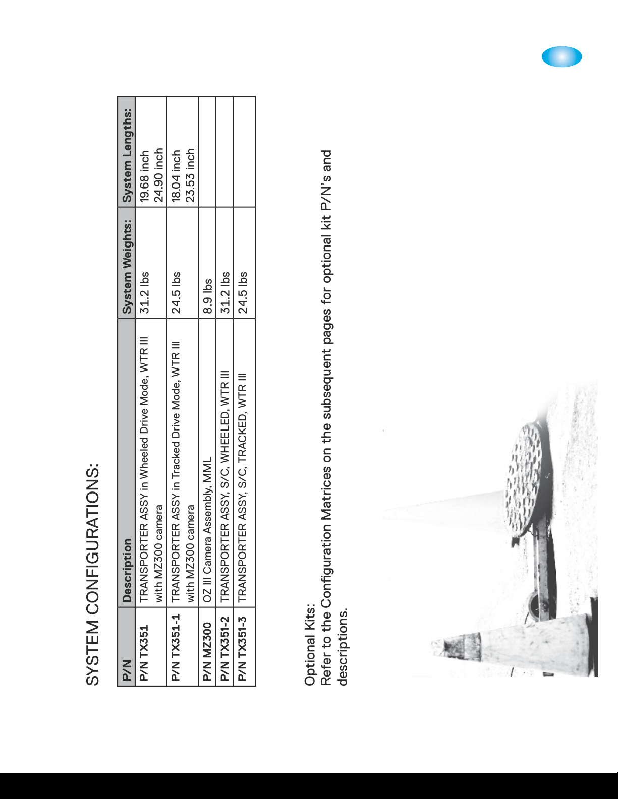
- wheeled transporter, P/N TX351, with wheel module P/N’s TX322 and P/N TX323
- or as a tracked transporter, P/N TX351-1, with track module P/N’s TX324 and P/N TX325,
to adapt to various pipe conditions.
• The unit can easily switch between wheeled and tracked drive mode with only a few screw
changes.
• Can inspect 6 inch through 24 inch pipelines, in either wheeled or tracked mode, without prior
stringing or other setup procedures.

1
CUES Inc.,WTR III User Manual | TX920 CUES Inc., WTR III User Manual | TX920
www.cuesinc.com,| salesinfo@cuesinc.com www.cuesinc.com,| salesinfo@cuesinc.com
• WTR III in tracked mode can use weighted adapters; in wheeled mode, WTR III can exibly use
weighted adapters as well as CUES existing spacers to center the camera in the pipe. The
conguration evolution allows greater weight-to-gain increased traction and larger bottom clearance for
larger size pipe.
• In wheeled mode (TX351), WTR III can inspect 6 inch diameter pipe with a large bottom clearance.
• In wheeled mode, WTR III can use all CUES existing wheel sets: from 6” steel or rubber wheels to
12”-15” pneumatic rubber wheels. Larger wheels enable faster travel speed in larger pipe: it can
travel at a maximum speed of ~60fpm with 6” rubber wheels (or 6” steel wheels) and ~120fpm with
the 12”-15” pneumatic wheels.
• WTR III comes with a new electric connector interface for easier operation and better protection against
leaks and damages. The motor transmission module and wheeled modules are waterproof, and the
tracked module sprockets have a self-cleaning mechanism — all of which contributes to a more reliable
and better performing system that’s capable of operating in severely dirty, sludgy, muddy, greasy, or
sandy, etc., or other dicult and hazardous environments.
• WTR III is capable of using dierent sizes (6”, 8”, 10-15”, 12-15”), dierent materials/structures and
traction mechanisms (rubber, steel with teeth, and pneumatic), CUES existing wheels in wheeled
mode, as well as using CUES track modules with contoured high traction cleats in tracked mode.
WTR III can be easily optimized to provide maximum performance versatility for various pipe size,
material, and conditions.
• In tracked drive mode, the tension can be adjusted on both the left and right side track modules to
achieve better performance and increased track cleat life.
• The cone-shaped motor housing and new smoother motor transmission prole facilitates easier, less
restricted passage through severe osets in forward drive and retrieval modes.
Features & Benets - continued:

CUES Inc.,WTR III User Manual | TX920 CUES Inc., WTR III User Manual | TX920
www.cuesinc.com,| salesinfo@cuesinc.com www.cuesinc.com,| salesinfo@cuesinc.com
2
CUES Inc.,WTR III User Manual | TX920 CUES Inc., WTR III User Manual | TX920
www.cuesinc.com,| salesinfo@cuesinc.com www.cuesinc.com,| salesinfo@cuesinc.com
SYSTEM DESCRIPTION
2 - in - 1
Unit
SYSTEM DESCRIPTION: WTR III
CUES oers the WTR III for customers that require an aordable but extraordinarily versatile
transporter that can operate with wheels or tracks to adapt to varying, dicult, and hazardous
pipelines ranging from ” diameter relined pipe up to ” storm pipes. The WTR III is distinguished
as the rst “modular” transporter in the CCTV pipeline inspection industry. While keeping a very
compact prole at its minimum conguration, WTR’s advanced modular design concept enables
end-users to switch between wheeled or tracked drive mode to adapt to dierent pipe conditions.
The WTR III in tracked drive mode has a similar small cross prole and shorter length as its predecessor,
CUES Ultra Shorty III. With an ” length (the same as the Ultra Shorty III), it can operate in ”
diameter pipe with more than ” bottom clearance. Using weighted adapters, WTR III in either
tracked or wheeled drive mode can inspect storm drain/wastewater pipelines up to ” in diameter.
WTR III in tracked drive mode can power drive at speeds from to feet per minute with standard
motor module; and with optional high-speed motor module (for tracked drive mode use only), it can
power drive at speeds from to feet per minute.
Without much increase in prole, but with signicant increase in top and bottom clearance, the
WTR III in wheeled drive mode can use all CUES Compact Pipe Ranger (CPR) wheel sets as well as
-” pipe spacer kits.
Since existing CUES wheel sets can be used, the end-user will have more exibility to adapt the WTR
III to various pipe conditions without incurring nancial burdens. In addition, the larger wheel size
enables the WTR III to travel faster in larger size pipes; approximately feet per minute (maximum
speed) with the CPR ”-” pneumatic wheels.

3
CUES Inc.,WTR III User Manual | TX920 CUES Inc., WTR III User Manual | TX920
www.cuesinc.com,| salesinfo@cuesinc.com www.cuesinc.com,| salesinfo@cuesinc.com
CUES Inc.,WTR III User Manual | TX920 CUES Inc., WTR III User Manual | TX920
www.cuesinc.com,| salesinfo@cuesinc.com www.cuesinc.com,| salesinfo@cuesinc.com
EQUIPMENT OVERVIEW
SYSTEM CONFIGURATIONS:
P/N Description System Weights: System Lengths:
P/N TX TRANSPORTER ASSY in Wheeled Drive Mode, WTR III
with MZ camera
. lbs 19.68 inch
24.90 inch
P/N TX- TRANSPORTER ASSY in Tracked Drive Mode, WTR III
with MZ camera
. lbs 18.04 inch
23.53 inch
P/N MZ300 OZ III Camera Assembly, MML . lbs
P/N TX351-2 TRANSPORTER ASSY, S/C, WHEELED, WTR III . lbs
P/N TX351-3 TRANSPORTER ASSY, S/C, TRACKED, WTR III . lbs
Optional Kits:
Refer to the Conguration Matrices on the subsequent pages for optional kit P/N’s and
descriptions.

CUES Inc.,WTR III User Manual | TX920 www.cuesinc.com,| salesinfo@cuesinc.com
Page 1 of 5WTR III in Recommended Configuration TX915
TITLE:
INSTR. SHT,WHEELED/TRACKED,MATRX,WTR III
DFTR:
DATE:
DWG. NO.:
TX915
CHKR:
DATE:
ECN:
14356
ENGR:
PS
DATE:
06/10/20
REV.:
D
MFG:
DATE:
MATERIAL:
NONE
MAT’L:
DATE:
FINISH:
NONE
PRODUCT:
WTR III
NEXT ASSY / USED ON:
Ф6”~Ф15” Pipe Wheeled Configuration Matrix
Configuration
6"
RUBBER
6"
STEEL
8"
RUBBER
8"
STEEL
10"
RUBBER
10"
STEEL
12"
RUBBER
12"
STEEL
15"
RUBBER
15"
STEEL
12"
PNEU
15"
PNEU
WHEEL KITS
N/A
TX923-3
WM308
WS906
WM310
WM310-2
WM310
WM310-2
WM310
WM310-2
WM312
WM312
HUB, Inner
none
None
WM089
(6x)
None
WM089
(6x)
none
WM089
(6x)
none
WM089
(6x)
None
WM100
(4x)
WM100
(4x)
HUB, Outer
none
none
WM090
(6x)
None
WM091
(6x)
none
WM091
(6x)
None
WM091
(6x)
None
none
none
WHEEL/TIRE
TX111
(6x)
TX108-3
(6x)
WM092
(6x)
WS112-1
(6x)
WM093
(6x)
WM108-1
(6x)
WM093
(6x)
WM108-1
(6x)
WM093
(6x)
WM108-1
(6x)
WT331
(4x)
WT331
(4x)
SPACER KITS
none
none
WM058
(6x)
WM058
(6x)
WM061
(6x)
WM061
(6x)
WM058 (6x)
WM061 (6x)
WM058 (6x)
WM061 (6x)
WM061
(12x)
WM061
(12x)
none
WM058 (6x)
WM061 (6x)
HUB SCREWS
none
none
103052
(18x)
none
102001
(18x)
none
102001
(18x)
None
102001
(18x)
None
none
none
CAPTIVE
SCREW
WM098-1
(6x)
WM098-1
(6x)
WM099-1
(6x)
HW2819
(6x)
None
none
None
None
None
None
none
none
MOTOR
CONN CABLE
TX342
(8.5” Lng)
TX342
(8.5” Lng)
TX342
(8.5” Lng)
TX342
(8.5” Lng)
TX342
(8.5” Lng)
TX342
(8.5” Lng)
TX342
(8.5” Lng)
TX342
(8.5” Lng)
TX342
(8.5” Lng)
TX342
(8.5” Lng)
TX342
(8.5” Lng)
TX342
(8.5” Lng)
ATTACHMENT
SCREW
none
none
none
none
HW1567
(1.5” Lng, 6x)
HW1567
(1.5” Lng, 6x)
HW1568
(2.0” Lng, 6x)
HW1568
(2.0” Lng, 6x)
HW1569
(2.5” Lng, 6x)
HW1569
(2.5” Lng, 6x)
HW1568
(2.0” Lng,4x)
HW1570
(3.5” Lng, 4x)
Weight
31.2 lbs
32.3 lbs
35.8 lbs
35.5 lbs
43.3 lbs
44.2 lbs
46.4 lbs
47.3 lbs
49.4 lbs
50.3 lbs
39.8 lbs
56.4 lbs
NOTE: 1.1 Spacer Kits (WM317 or WM317-1) are required for 7~15” pipe configurations; and the kits include all wheel attachment screws.
1.2 Apply adequate Anti-Seize (LPS Nickel Part No. 03908, CUES #CS407) to wheel mounting screws for all configurations.
1.3 Tighten the wheel mounting screws with 15 ft-lbs torque.
1.4 When setting up for relined pipe select configuration for next smallest pipe and add 6x WM223 wheel spacers (included in WM317).

CUES Inc., WTR III User Manual | TX920
www.cuesinc.com,| salesinfo@cuesinc.com
Page 2 of 5WTR III in Recommended Configuration TX915
Ф18”~Ф24” Pipe Wheeled Configuration Matrix
Configuration
18"
RUBBER
18"
STEEL
21"
RUBBER
21"
STEEL
24"
RUBBER
24"
STEEL
18"
PNEUM
21"
PNEUM
24"
PNEUM
WHEEL KIT
EXTENDER KIT
WM310
TX912
WM310-2
TX912
WM310
TX912
WM310-2
TX912
WM310
TX912
WM310-2
TX912
WM312
TX912
WM312
TX912
WM312
TX912
HUB, Inner
WM089 (6x)
none
WM089 (6x)
none
WM089 (6x)
none
WM100 (4x)
WM100 (4x)
WM100 (4x)
HUB, Outer
WM091 (6x)
none
WM091 (6x)
none
WM091 (6x)
none
none
None
none
WHEEL/TIRE
WM093 (6x)
WM108-1 (6x)
WM093 (6x)
WM108-1 (6x)
WM093 (6x)
WM108-1 (6x)
WT331 (4x)
WT331 (4x)
WT331 (4x)
HUB SCREWS
103052 (18x)
none
103052 (18x)
none
102001 (18x)
none
none
none
none
WHEEL/TIRE
MOUNT
SCREWS
HW2237 (6x)
(.312-24 x .63”)
HW2237 (6x)
or WM098-1 (6x)
(.312-24 x .63”)
HW2237 (6x)
(.312-24 x .63”)
HW2237 (6x)
or WM098-1 (6x)
(.312-24 x .63”)
HW2237 (6x)
(.312-24 x .63”)
HW2237 (6x)
or WM098-1 (6x)
(.312-24 x .63”)
HW1568 (6x)
(.312-24 x 2.0”)
HW1568 (6x)
(.312-24 x 2.0”)
HW1568 (6x)
(.312-24 x 2.0”)
ADAPTERS
(-1 = BRASS)
TX330 (1x)
TX331 (1x)
TX332 (1x)
TX333 (1x)
TX333-1 (1x)
TX330 (1x)
TX331 (1x)
TX332 (1x)
TX333 (1x)
TX333-1 (1x)
TX332 (2x)
TX333 (2x)
TX333-1 (1x)
TX332 (2x)
TX333 (2x)
TX333-1 (1x)
TX330 (1x)
TX331 (1x)
TX332 (2x)
TX333 (2x)
TX333-1 (1x)
TX330 (1x)
TX331 (1x)
TX332 (2x)
TX333 (2x)
TX333-1 (1x)
TX331 (1x)
TX332 (1x)
TX333-1 (1x)
TX330 (1x)
TX331 (1x)
TX332 (1x)
TX333 (1x)
TX333-1 (1x)
TX332 (2x)
TX333 (2x)
TX333-1 (1x)
SHAFT
EXTENDER
TX336-15
TX336-15
TX336-18
TX336-18
TX336-21
TX336-21
TX336-12
TX336-15
TX336-18
MOTO CONN.
4-PIN CABLE
TX342-1
16” Length
TX342-1
16” Length
TX342-1
16” Length
TX342-1
16” Length
TX342-1
16” Length
TX342-1
16” Length
TX342-1
16” Length
TX342-1
16” Length
TX342-1
16” Length
CONNECT
STRIP &
SCREWS
TX337-15 (1x)
WM098-1 (2x)
or WM098 (2x)
TX337-15 (1x)
WM098-1 (2x)
or WM098 (2x)
TX337-18 (1x)
WM098-1 (2x)
or WM098 (2x)
TX337-18 (1x)
WM098-1 (2x)
or WM098 (2x)
TX337-21 (1x)
WM098-1 (2x)
or WM098 (2x)
TX337-21 (1x)
WM098-1 (2x)
or WM098 (2x)
none
TX337-15 (1x)
WM098-1 (2x)
or WM098 (2x)
TX337-18 (1x)
WM098-1 (2x)
or WM098 (2x)
Weight
47.7 lbs
48.6 lbs
52.3 lbs
53.2 lbs
55.8 lbs
56.7 lbs
37.8 lbs
50.4 .lbs
56.4 lbs
NOTE: 2.1 Apply adequate Anti-Seize (LPS Nickel Part No. 03908, CUES #CS407) to wheel mounting screws for all configurations.
2.2 Tighten the wheel mounting screws with 15 ft-lbs torque.
2.3 Substitution of brass adapters for aluminum adapters in the leftmost (outboard port) position is recommended to rebalance the transporter’s center of gravity effected by the offset motor position.
2.4 Wear strips (TX024) included in adapter kit (TX903 &TX912) are for use with track configuration only.

CUES Inc.,WTR III User Manual | TX920 www.cuesinc.com,| salesinfo@cuesinc.com
Page 3 of 5WTR III in Recommended Configuration TX915
Φ6” ~ Φ24” Pipe Tracked Configuration Matrix
Configuration
6"
8" RELINED
8"
10"
12"
15"
18"
21"
24"
KIT Number
TX903
TX903
TX903
TX903
TX903
TX903
TX912
TX912
TX912
ADAPTERS
(-1 = BRASS)
none
TX334 (1x)
TX335 (1x)
TX335-1 (1x)
TX330 (1x)
TX331 (1x)
TX331-1 (1x)
TX330 (2x)
TX331 (2x)
TX331-1 (1x)
TX332 (1x)
TX333 (1x)
TX333-1 (1x)
TX330 (1x)
TX331 (1x)
TX332 (1x)
TX333 (1x)
TX333-1 (1x)
TX332 (2x)
TX333 (2x)
TX333-1 (1x)
TX330 (1x)
TX331 (1x)
TX332 (2x)
TX333 (2x)
TX333-1 (1x)
TX332 (3x)
TX333 (3x)
TX333-1 (1x)
SHAFT EXTENDER
none
TX107
TX336-8
TX336-10
TX336-12
TX336-15
TX336-18
TX336-21
TX336-24
MOTOR CONN.
4-PIN CABLE
TX342
8.5” Length
TX342
8.5” Length
TX342
8.5” Length
TX342
8.5” Length
TX342
8.5” Length
TX342
8.5” Length
TX342-1
16” Length
TX342-1
16” Length
TX342-1
16” Length
CONNECT STRIP
& SCREWS
none
none
none
none
none
TX337-15 (1x)
WM098-1 (2x)
or WM098 (2x)
TX337-18 (1x)
WM098-1 (2x)
or WM098 (2x)
TX337-21
WM098-1 (2x)
or WM098 (2x)
TX337-24 (1x)
WM098-1 (2x)
or WM098 (2x)
Weight
33.4 lbs
34.8 lbs
35.7 lbs
38.0 lbs
41.3 lbs
43.6 lbs
49.2 lbs
51.5 lbs
57.1 lbs

CUES Inc., WTR III User Manual | TX920
www.cuesinc.com,| salesinfo@cuesinc.com
Page 4 of 5WTR III in Recommended Configuration TX915
TX903: KIT, ADAPTER EXTENSION, FIT Φ7” ~ Φ15” PIPE, TRACKED WTR III
TX903
(7”-15” pipe)
1 ea.
TX334
Adapter, .5X Width, Righthand, WTR III, Aluminum
1 ea.
TX335
Adapter, .5X Width, Lefthand, WTR III, Aluminum
1 ea.
TX335-1
Adapter, .5X Width, Lefthand, WTR III, Brass
2 ea.
TX330
Adapter, 1X Width, Righthand, WTR III, Aluminum
2 ea.
TX331
Adapter, 1X Width, Lefthand, WTR III, Aluminum
1 ea.
TX331-1
Adapter, 1X Width, Lefthand, WTR III, Brass
1 ea.
TX332
Adapter, 3X Width, Righthand, WTR III, Aluminum
1 ea.
TX333
Adapter, 3X Width, Lefthand, WTR III, Aluminum
1 ea.
TX333-1
Adapter, 3X Width, Lefthand, WTR III, Brass
1 ea.
TX107
Shaft Extender, Drive, 1” LG (8” Relined), WTR III
1 ea.
TX336-8
Shaft Extender, Drive, 1.5” LG, WTR III
1 ea.
TX336-10
Shaft Extender, Drive, 3” LG, WTR III
1 ea.
TX336-12
Shaft Extender, Drive, 4.5” LG, WTR III
1 ea.
TX336-15
Shaft Extender, Drive, 6” LG, WTR III
1 ea.
TX337-15
Strip, Adapter Connection, 8.5” LG, WTR III
2 ea. WM098-1
(or WM098) Screw, Captive, Hex, 5/16-24UNF x 0.625”
9 ea.
TX024
Wear Strip, 8 inch, Adapter, US III
18 ea.
HW1224
Screw, Pan, Phil, 6-32 x .25, Brass
1 ea.
TX915
Instr Sht, Config Matrix, Wheeled/Tracked, WTR III
1 ea.
TX093
Skid Plate, 8”+ Track/18”+ Wheel, WTR III
2 ea.
103063
Screw, Flat, Phil, 8-32 x .73, 18-8 SST
1 ea.
TX093-INST
Instruction Sheet, Skid Plate, WTR III
TX912: KIT, ADAPTER EXTENSION (from Φ7” ~ Φ15” PIPE CONFIGURATIONS), FIT Φ18” ~
Φ24” PIPE, WHEELED & TRACKED WTR III
TX912
(18”-24” pipe)
1 ea.
TX330
Adapter, 1X Width, Righthand, WTR III, Aluminum
1 ea.
TX331
Adapter, 1X Width, Lefthand, WTR III, Aluminum
1 ea.
TX331-1
Adapter, 1X Width, Lefthand, WTR III, Brass
2 ea.
TX332
Adapter, 3X Width, Righthand, WTR III, Aluminum
2 ea.
TX333
Adapter, 3X Width, Lefthand, WTR III, Aluminum
1 ea.
TX333-1
Adapter, 3X Width, Lefthand, WTR III, Brass
1 ea.
TX336-12
Shaft Extender, Drive, 4.5” LG, WTR III
1 ea.
TX336-15
Shaft Extender, Drive, 6” LG, WTR III
1 ea.
TX336-18
Shaft Extender, Drive, 9” LG, WTR III
1 ea.
TX336-21
Shaft Extender, Drive, 10.5” LG, WTR III
1 ea.
TX336-24
Shaft Extender, Drive, 12” LG, WTR III
1 ea.
TX337-15
Strip, Adapter Connection, 8.5” LG, WTR III
1 ea.
TX337-18
Strip, Adapter Connection, 11.5” LG, WTR III
1 ea.
TX337-21
Strip, Adapter Connection, 13” LG, WTR III
1 ea.
TX337-24
Strip, Adapter Connection, 16” LG, WTR III
8 ea. WM098-1
(or WM098)
Screw, Captive, Hex, 5/16-24UNF x 0.625”
12 ea.
HW2237
Screw, Socket Cap, Hex, 5/16-24UNF x 0.625”
6 ea.
TX024
Wear Strip, 8 inch, Adapter, US III
12 ea.
HW1224
Screw, Pan, Phil, 6-32 x .25, Brass
1 ea.
TX342-1
Cable Assembly, 16” long, 4-pin, WTR III
1 ea.
TX915
Instr Sht, Config Matrix, Wheeled/Tracked, WTR III
1 ea.
TX093
Skid Plate, 8”+ Track/18”+ Wheel, WTR III
2 ea.
103063
Screw, Flat, Phil, 8-32 x .73, 18-8 SST
1 ea.
TX093-INST
Instruction Sheet, Skid Plate, WTR III

CUES Inc.,WTR III User Manual | TX920 www.cuesinc.com,| salesinfo@cuesinc.com
Page 5 of 5WTR III in Recommended Configuration TX915
TX913: KIT, ADAPTER EXTENSION, FIT Φ18” ~ Φ24” PIPE, TRACKED WTR III (USED WITH
TX903)
TX913
(18”-24” pipe)
2 ea.
TX332
Adapter, 3X Width, Righthand, WTR III, Aluminum
2 ea. TX333 Adapter, 3X Width, Lefthand, WTR III, Aluminum
1 ea.
TX333-1
Adapter, 3X Width, Lefthand, WTR III, Brass
1 ea.
TX336-18
Shaft Extender, Drive, 9” LG, WTR III
1 ea. TX336-21 Shaft Extender, Drive, 10.5” LG, WTR III
1 ea. TX336-24 Shaft Extender, Drive, 12” LG, WTR III
1 ea. TX337-18 Strip, Adapter Connection, 11.5” LG, WTR III
1 ea.
TX337-21
Strip, Adapter Connection, 13” LG, WTR III
1 ea.
TX337-24
Strip, Adapter Connection, 16” LG, WTR III
6 ea. WM098-1
(or WM098) Screw, Captive, Hex, 5/16-24UNF x 0.625”
1 ea.
TX342-1
Cable Assembly, 16” long, 4-pin, WTR III
1 ea. TX915 Instr Sht, Config Matrix, Wheeled/Tracked, WTR III
1 ea. TX093 Skid Plate, 8”+ Track/18”+ Wheel, WTR III
2 ea.
103063
Screw, Flat, Phil, 8-32 x .73, 18-8 SST
1 ea. TX093-INST
Instruction Sheet, Skid Plate, WTR III
TX914: KIT, ADAPTER EXTENSION, FIT Φ18” ~ Φ24” PIPE, WHEELED WTR III (USED WITH
WM310, WM310-1, WM312, OR TX922)
TX9
14
(18”
-24” pipe)
1 ea.
TX330
Adapter, 1X Width, Righthand, WTR III, Aluminum
1 ea. TX331
Adapter, 1X Width, Lefthand, WTR III, Aluminum
1 ea.
TX331-1
Adapter, 1X Width, Lefthand, WTR III, Brass
2 ea.
TX332
Adapter, 3X Width, Righthand, WTR III, Aluminum
2 ea. TX333
Adapter, 3X Width, Lefthand, WTR III, Aluminum
1 ea. TX333-1
Adapter, 3X Width, Lefthand, WTR III, Brass
1 ea. TX336-12
Shaft Extender, Drive, 4.5” LG, WTR III
1 ea.
TX336-15
Shaft Extender, Drive, 6” LG, WTR III
1 ea.
TX336-18
Shaft Extender, Drive, 9” LG, WTR III
1 ea. TX336-21
Shaft Extender, Drive, 10.5” LG, WTR III
1 ea. TX337-15
Strip, Adapter Connection, 8.5” LG, WTR III
1 ea. TX337-18
Strip, Adapter
Connection, 11.5” LG, WTR III
1 ea.
TX337-21
Strip, Adapter Connection, 13” LG, WTR III
6 ea.
WM098-1
(or WM098)
Screw, Captive, H
ex, 5/16-24UNF x 0.625”
12 ea. HW2237
Screw,
Socket Cap, Hex, 5/16-24UNF x 0.625”
1 ea.
TX342-1
Cable Assembly, 16” long, 4-pin, WTR III
1 ea. TX915
Instr Sht, Config Matrix, Wheeled/Tracked, WTR III
1 ea. TX093
Skid Plate, 8”+ Track/18”+ Wheel, WTR III
2 ea.
103063
Screw, Flat, Phil, 8-32 x .73, 18-8 SST
1 ea. TX093-INST
Instruction Sheet, Skid Plate, WTR III

CUES Inc., WTR III User Manual | TX920
www.cuesinc.com,| salesinfo@cuesinc.com

4SYSTEM SET-UP & INSTALLATION
CUES Inc.,WTR III User Manual | TX920 CUES Inc., WTR III User Manual | TX920
www.cuesinc.com,| salesinfo@cuesinc.com www.cuesinc.com,| salesinfo@cuesinc.com
RIGHT SIDELEFT SIDE
IMPORTANT! When removing the
wheels or tracks, always start with the
left side (looking from the rear of the
transporter). When installing wheel or
tracks, start on the right side.
RIGHT SIDE
LEFT SIDE
RIGHT SIDE
TX324
LEFT SIDE
TX325
TX325
TX323
TX324
TX322

4
CUES Inc.,WTR III User Manual | TX920 CUES Inc., WTR III User Manual | TX920
www.cuesinc.com,| salesinfo@cuesinc.com www.cuesinc.com,| salesinfo@cuesinc.com
SYSTEM SET-UP & INSTALLATION
CONVERTING THE WTR III FROM WHEELS TO TRACKS
IMPORTANT! When removing the wheels or tracks
(looking from the rear of the transporter), always start
with the left side. When installing wheel or tracks, start
on the right side.
To remove the wheels:
START WITH THE LEFT SIDE OF THE
TRANSPORTER FIRST!
1. Cut the large tie-wrap that’s retaining the large
cable to the motor transmission module.
2. Using a 3/16” hex-bit wrench, remove the screws
that secure the wheels to the transporter.
3. Using a 3/16” hex-bit wrench, remove the bolt
that secures the left side wheel module.
2
3
1
IMPORTANT!
Wheels must be torqued to
15 ft lbs. prior to usage!

4SYSTEM SET-UP & INSTALLATION
CUES Inc.,WTR III User Manual | TX920 CUES Inc., WTR III User Manual | TX920
www.cuesinc.com,| salesinfo@cuesinc.com www.cuesinc.com,| salesinfo@cuesinc.com
CONVERTING THE WTR III FROM WHEELS TO TRACKS
ON THE RIGHT SIDE OF THE TRANSPORTER...
3. Using a 3/16” hex bit wrench, remove the bolt that secures the left side wheel module to the brass
body.
4. Using a 9/64” hex bit wrench, remove the three screws that attach the right wheel module to the
motor assembly.
5. Slide the wheel module o of the shaft.
34
5
CONVERTING THE WTR III FROM TRACKS TO WHEELS
NOTE: Wheel module Installation is achieved by performing the opposite steps of this removal procedure.

4
CUES Inc.,WTR III User Manual | TX920 CUES Inc., WTR III User Manual | TX920
www.cuesinc.com,| salesinfo@cuesinc.com www.cuesinc.com,| salesinfo@cuesinc.com
SYSTEM SET-UP & INSTALLATION
TO INSTALL THE RIGHT TRACK MODULE
1. Verify that the key is still in place on the shaft.
Place the track against the motor transmission
module. Obtain the right track module. Turn the
track until the keyway is aligned with the key on
the shaft and slide it in. Apply a small amount
of blue thread-locker on the three captive
mounting screw threads.
2. Install the right-side track module onto the motor
module. IMPORTANT! Ensure that all 3 screws
are pulled down evenly while tightening.
3. Once bottomed-out, back-o (1) turn to
prevent the track module from binding on the
motor transmission module. Do not fully tighten
the screws yet.
1
2
3
CONVERTING THE WTR III FROM
WHEELS TO TRACKS

4SYSTEM SET-UP & INSTALLATION
CUES Inc.,WTR III User Manual | TX920 CUES Inc., WTR III User Manual | TX920
www.cuesinc.com,| salesinfo@cuesinc.com www.cuesinc.com,| salesinfo@cuesinc.com
TO INSTALL THE CAMERA CRADLE AND LEFT TRACK MODULE
4. Install the camera cradle module onto the right side track module.
5. Align the slot of the left track module with the pin on the shaft of the motor transmission module
and install.
45
CONVERTING THE WTR III FROM WHEELS TO TRACKS
Table of contents