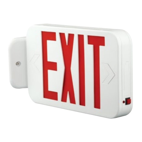
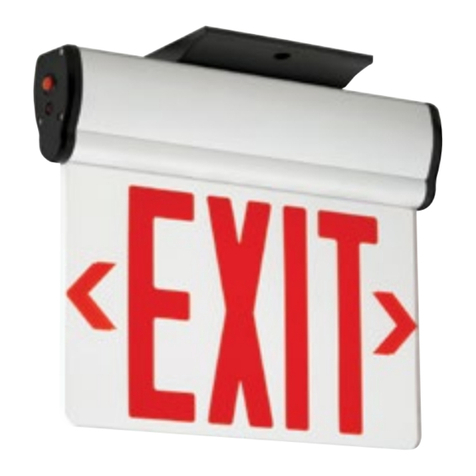
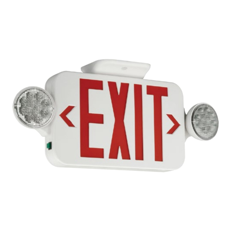
Current Dual-Lite LED1EM Operating instructions

INSTALLATION/OWNERS
MANUAL
Models with batteries must be stored in a cool place
(80°F max., preferably 68°F) and installed within 90 days !
IMPORTANT: In signs with battery, red and black lead wires must be connected
to battery or sign will not operate upon power outage !!!
NOTE: Take care not to bend "EXIT" board or "EXIT" board plugs during installation.
Though reinforced, copper tracings can be broken and the sign rendered inoperable.
* All models listed above are rated "Suitable for damp locations".
IMPORTANT SAFEGUARDS
READ AND FOLLOW ALL SAFETY INSTRUCTIONS
1) Do not use outdoors*.
2) Do not mount near gas or electrical heaters.
3) Use caution when servicing batteries. Battery acid can cause burns to skin and
eyes. If acid is spilled on skin or in eyes, ush acid with fresh water and contact
a physician immediately.
4) Mount exit sign in locations and at heights where it will not be subjected to
tampering by unauthorized personnel.
5) These models are not designed for operation of remote lamps.
6) Use of any accessory equipment not recommended by the manufacturer may
cause an unsafe condition.
7) All servicing should be performed by qualied service personnel.
8) Do not use this equipment for other than intended use.
SAVE THESE INSTRUCTIONS !!!
FOR MODELS: LED1EM, LED2EM, LED1AC, LED2AC,
PLED1EM, PLED2EM, PLED1AC, PLED2AC,

P-1
J-1
SOUNDER OPTION
(RED+/BLACK-)
12 TO 24 VOLTS AC OR DC
FAI OPTION
(RED+/BLACK-)
TO EXIT
(RED+/BLUE-)
FIELD SELECTABLE
(FLASH/NON-FLASH)
JUMPER
TO BATTERY
(RED+/BLACK-)
SW1
6 5 4 3 2 1
P-3
P-2
TRANSFORMER
1790-000
Circuit Board CB2e
(In Battery Units)
P-1: Optional FAP
Hookup Wires
(factory installed)
ALL BATTERY UNITS HAVE (FIELD SELECTABLE) EMERGENCY FLASHING OPTION
If you want the unit to ash during AC power failure, place jumper (see above) on only the upper post
of J-1. If you want the unit to stay on solid during AC power failure, place jumper across both posts of
J-1.
FIRE ALARM OPTION (FAP)
The ashing FAP option requires eld wiring to the red and black wires provided on the connector P-
3 (on Battery units) and P-1 (on AC only units). The FAP can be activated with a 12 to 24 VAC signal, or
a polarized input (positive to red) of 12 to 24 VDC. The maximum current required to activate the FAP
is less than 2 MA per exit.
NOTE: If you are using a system that reverses polarity upon alarm you should connect its positive
to the black wire and its negative output to the red wire. This way when the polarity reverses the
FAP will activate. SPECIAL NOTE: Regardless of the selection of J-1, the exit will ash with the
introduction of FAP signal.
BEEPER OPTION (AVAILABLE ONLY ON BATTERY UNITS)
The audible beeper is a factory installed option on pins 3 & 4 of P-3, and requires no eld wiring. If
ordered as a FAP-BPR option (Fire alarm beeper), it becomes active only with the introduction of an
FAP signal. If ordered as a BPR option (Beeper only), it will become active with the loss of AC power.
PAGE 3
BLACK WIRE
FOR 120v HOOKUP ONLY
WASHER
LOCKNUT
ORANGE WIRE
FOR 277v HOOKUP ONLY
NIPPLE
GREEN
GROUND
WIRE
WASHERS
HEX NUTS
EXIT BOARD
EXIT BOARD PLUG
END PLATE
SCREW
END PLATE
END PLATE
SCREW
WASHERS
CANOPY SCREW
OUTLET BOX SCREWS
(NOT PROVIDED)
FIXTURE BAR
OUTLET BOX
(NOT PROVIDED)
CANOPY SCREW
CANOPY
ARROW KNOCKOUT(s):
Carefully, punch the point of the arrow
through the back of the plate. Then
carefully work it back and forth to remove.
EXIT HOUSING
WIRING
KNOCKOUT
WHITE
WIRE
PAGE 3
GROUND SCREW
Circuit Board CB4B (In AC Only Units)
SPECIAL NOTE:
After connecting Unit to AC
power, the loose Transformer
Wires must be routed and
secured to Unit every
3 inches, using Adhesive-
Backed Mounting Platforms
and Cable Ties (provided).
PAGE 2
INSTALLATION
1). Unpack and check for concealed transit damage. Report all transit damage to delivering carrier and le claim.
2). Remove END PLATE (two END PLATE SCREWS).
3). Carefully slide EXIT BOARD(s), FACEPLATE(s) and SHIELD(s), half-way out.
4). Disconnect EXIT BOARD PLUG(s).
5). Carefully remove EXIT BOARD(s), FACEPLATE(s), and SHIELD(s) from unit.
6). Select (top, end, or back) WIRING KNOCK-OUT and remove it.
7). OPTIONAL: Mount CANOPY to EXIT HOUSING with 2 CANOPY SCREWS, WASHERS & HEX NUTS (provided).
8). INSURE AC OUTLET POWER IS OFF TO PREVENT ELECTROCUTION !!!
9). Mount FIXTURE BAR to OUTLET BOX (with 2 OUTLET BOX SCREWS).
10). Screw NIPPLE into FIXTURE BAR.
11). Locate wires from exit sign transformer. Select and use either the BLACK WIRE (for 120v hookup) or ORANGE WIRE (for 277v
hookup). Use only one of these two wires. Unused wire should be capped.
12). Insert selected (BLACK or ORANGE) WIRE along with WHITE WIRE and GREEN GROUND WIRE through LOCKNUT, WASHER,
KNOCKOUT HOLE, NIPPLE, and BRACKET BAR.
13). Attach wires to service - insuring proper connection (white to white, black to black or orange to 277v, and green to GROUND SCREW
provided on FIXTURE BAR.
14). Slip HOUSING AND WASHER onto NIPPLE. (Secure with LOCKNUT. CAUTION: SECURE, BUT DO NOT OVER TIGHTEN !!!)
15). IMPORTANT: In signs with battery, red and black lead wires must be connected to battery or sign will not work upon power outage !!!
16). Select ash or no ash on AC fail with J-1 (See page 3).
17). Select proper ARROW KNOCKOUTS and very carefully remove them (SEE DETAIL ABOVE)!
18). Slide EXIT BOARD(s) back halfway into unit and reconnect EXIT BOARD PLUG(s).
19). Slide EXIT BOARD(s), FACEPLATE(s) and SHIELD(s), back into unit. Replace END PLATE (two END PLATE SCREWS).
20). Apply AC power and Push Test Button... EXIT !!!

CHECKING DIAGNOSTIC INDICATORS
The red indicator LED near the test button indicates that the battery is being charged.
The green LED indicates that the unit is receiving power.
Once battery is charged; continuous red and green indicators
indicate dead battery or malfunction and service is required.
Continuous red and green is normal up to 24 hours after extended power failure.
TEST BUTTON
Pressing the test button will simulate a power outage. After checking indicators (as above), press test
button to check the entire emergency circuitry. If the "EXIT" lights up during normal operation and
during this test, it is operating!
Once fully charged, the battery will automatically recharge in 24 hours. Our charging circuitry
maintains optimum battery voltage levels to provide superior battery life. If "emergency ashing"
is selected, this unit is UL listed to operate for 12 hours for LED1EM/PLED1EM and 8 hours for
LED2EM/PLED2EM. If "non ashing" is selected, this unit is UL listed to operate in the emergency
mode for 6 hours for LED1EM/PLED1EM and 4 hours for LED2EM/PLED2EM.
The emergency ashing feature is intended for locations where permitted by local codes. Flash rate
is 68 cycles/minute (±10%) at 50% duty cycle. Not intended to be cycled on and o by external control
except when factory equipped with FAP (optional re alarm interface).
REPLACEMENT PARTS
NOTE: Replace with original equipment only. Use of other batteries will void the U.L. listing.
LED1AC/PLED1AC and LED2AC/PLED2AC Circuit Diagram
BATTERY
TO SIGN FACE
3
P-1
1
24
TRANSFORMER
BLUE
BLUE
5
6
TO SIGN FACE
4
6
P-1
BLUE RED
BLUE
BLUE
1
2
ORANGE (277V)
BLACK (120V)
WHITE (COM.)
GREEN (GND)
TRANSFORMER
ORANGE (277V)
BLACK (120V)
RED BLACK
WHITE (COM.)
GREEN (GND)
12 TO 24 VOLTS AC OR DC
FAP OPTION
3
5
LED1EM/PLED1EM and LED2EM/PLED2EM Circuit Diagram
currentlighting.com/dual-lite
© 2022 HLI Solutions, Inc. All rights reserved. Information and specifications subject to change
without notice. All values are design or typical values when measured under laboratory conditions.
Page 4 of 4
Rev 05/31/22
ledseries-installinstr-0603385_a_R01
This manual suits for next models
6
Other Current Monitor manuals
