LCD Screen
Trouble Shooting
Power Info:
Channel NO.:
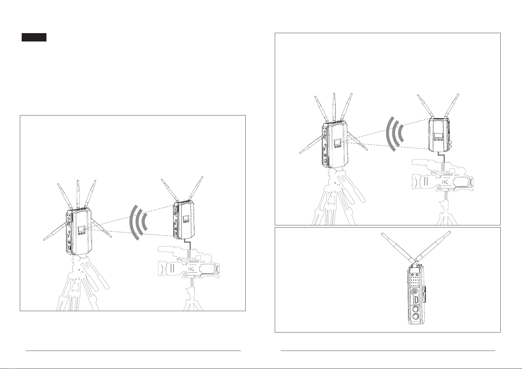
Wireless Signal
Wireless Link
Video Connect
Wireless Signal:
LINK:
VIDEO:
Power Info
Channel NO.
Solutions:
Power on transmitter.
Place the TX or RX onto the base and replace them erectly.
Move the receiver closer to the transmitter.
Reduce the number of solid walls between TX and RX.
Move the receiver closer to the transmitter.
Rematch the code of transmitter and receiver.
Power off other independent transmitter, place the
receiver away from the other sources of interference.
Connect the transmitter to video source by SDI/HDMI cable.
Power ON the video source.
Switch the Video source to SDI/HDMI output.
Remove and then re-plug the cable of transmitter
Reboot the transmitter.
Change the SDI/HDMI cable.
Switch the output video resolution to other modes.
Replaced with HDCP-certified TV/Monitor.
Power on receiver.
Connect receiver to TV/Monitor via SDI/HDMI cable.
Switch TV/Monitor to SDI/HDMI input.
Remove then re-plug the SDI/HDMI cable.
Switch the TV/Monitor to normal operation mode.
Reboot the receiver.
Re-plug the cable of the receiver or TV/Monitor
Reboot the receiver
Please contact your retailer
Unplug and then plug the HDMI cable of the receiver or TV.
Unplug and then plug the HDMI cable of the TX and player.
Reboot the transmitter and receiver.
OSD Information on TV
Image
Displaying “Link Connecting...” for long time
Transmitter is not electrified.
Transmitter or receiver is not placed erectly.
The transmitter and receiver are too far away.
Several solid wall partition TX and RX.
There are too many obstacles between TX and RX.
Haven't matched the code of TX and RX.
There is other transmitter which is under working
condition near the receiver.
No Video Signal received
Transmitter and video source are not connected.
The video source is turned OFF.
Video source were NOT switched to SDI/HDMI output.
Bad contact of cable of transmitter
Abnormal working of transmitter
Problem with cable between TX and video source
Player NOT support the output resolution format.
The TV/Monitor NOT support HDCP authentication.
No signal input to Receiver or TV/Monitor
Receiver is turned OFF.
Receiver and TV are not connected.
TV/Monitor NOT switched to SDI/HDMI input.
No image appear on TV/Monitor
Bad contact of the cable of receiver or TV/monitor
TV/Monitor turn into standby mode
Abnormal working of receiver.
Abnormal color on TV screen
Bad contact of receiver or cable.
Abnormal working of receiver
Receiver failure
Bad contact of cable of receiver or TV/moniter.
Bad contact of cable of transmitter or video source.
Abnormal working of transmitter or receiver
Troubles & Possible Reasons:
Display the current power supply status
Display the current Channel NO. of device
Display the networking signal status
LINK means the wireless connecting is OK
VIDEO means the video signal is OK
Transmitter support long pressing "HDMI/SDI" key to manually switch SDI audio mode.
When there is no audio from SDI input, you can manually switch SDI audio mode.
This function is only valid for the SDI interface and does not affect the HDMI interface.
Auto
SDI Audio mode is set to 0 by default
Long press “HDMI/SDI” key to switch to SDI audio mode 1
Auto
Supports full PSF resolutions
Supports full PSF resolutions
25PFS in = 25PFS out
29.97PSF=29.97PSF out
30PSF in = 30PSF out
23.98P in=23.98P out
24P in=24P out
25P in=25P out
29.97P in=29.97P out
30P in=30P out
50i in = 50i out
59.94i in = 59.94i out
60i in = 60i out