CyberPower RMCARD205 User manual

Copyright © 2021 Cyber Power Systems, Inc. All rights reserved.
K01-E000001-14
User’s Manual
The Remote Management Card allows
a UPS system and environmental
sensor to be managed, monitored,
and configured.
Remote Management Card
RMCARD205 / RMCARD305

TABLE OF CONTENTS
Introduction..........................................................................................................................3
Installation Guide ...............................................................................................................6
Web Interface....................................................................................................................10
Command Line Interface.............................................................................................. 38
Reset to Factory Default Setting / Recover from a Lost Password ...........64
RMCARD Firmware Upgrade ......................................................................................65
Save and Restore Configuration Settings.............................................................. 71
Upload SSH Host key via Secure Copy (SCP) ..................................................... 73
Troubleshooting ..............................................................................................................74
Conformance Approvals .............................................................................................. 75
Appendix 1: IP Address Identification for CyberPower Remote
Management Card........................................................................................................... 76
Appendix 2: How to Configure a RMCARD User Account in Authentication
Servers................................................................................................................................. 78
Appendix 3: UPS Firmware Upgrade ...................................................................... 79
Appendix 4: Software Support..................................................................................80
Appendix 5: RMCARD Adapter Guide .................................................................... 82

CyberPower Remote Management System
3
Introduction
Overview
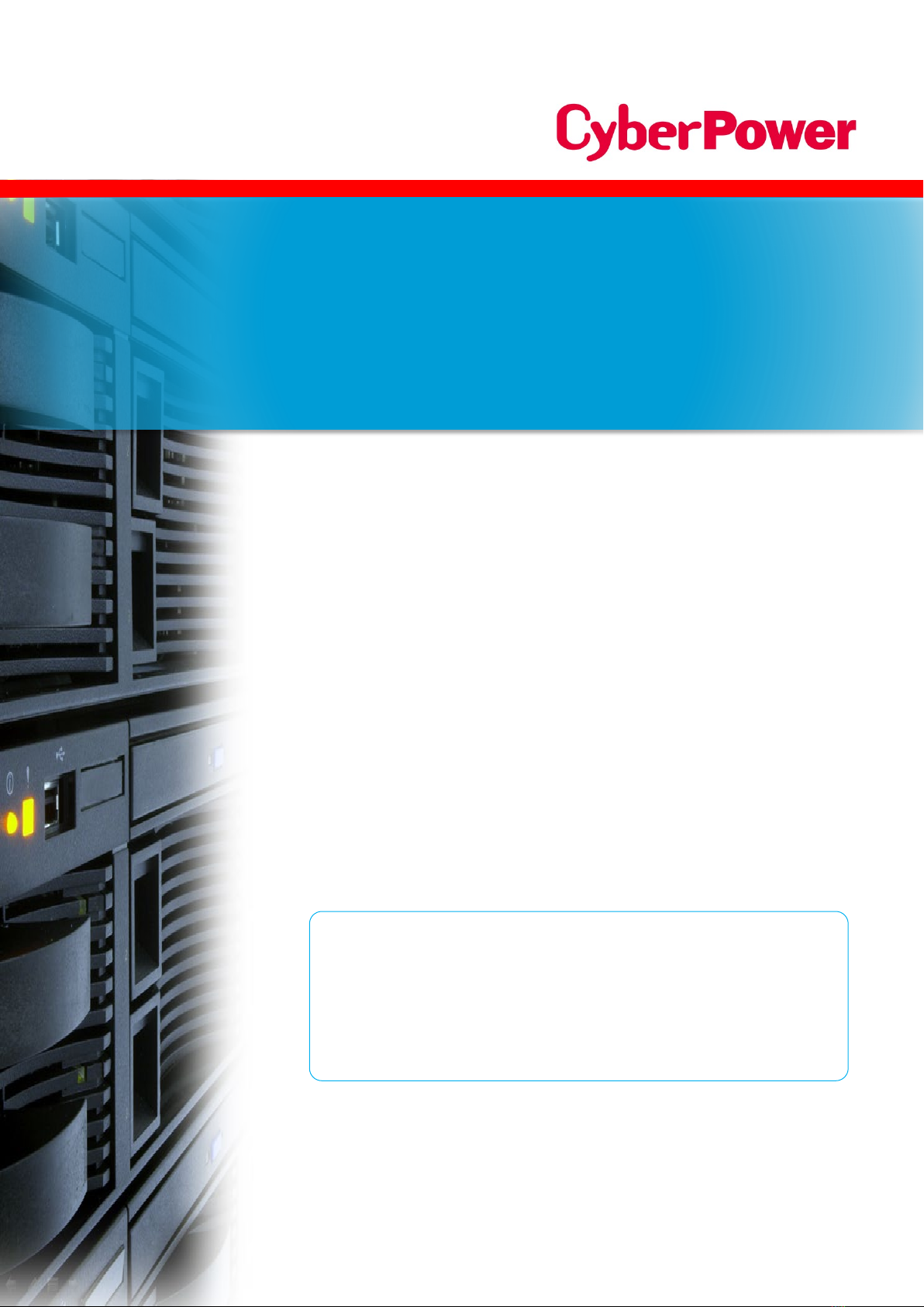
The CyberPower Remote Management Card allows for remote monitoring and
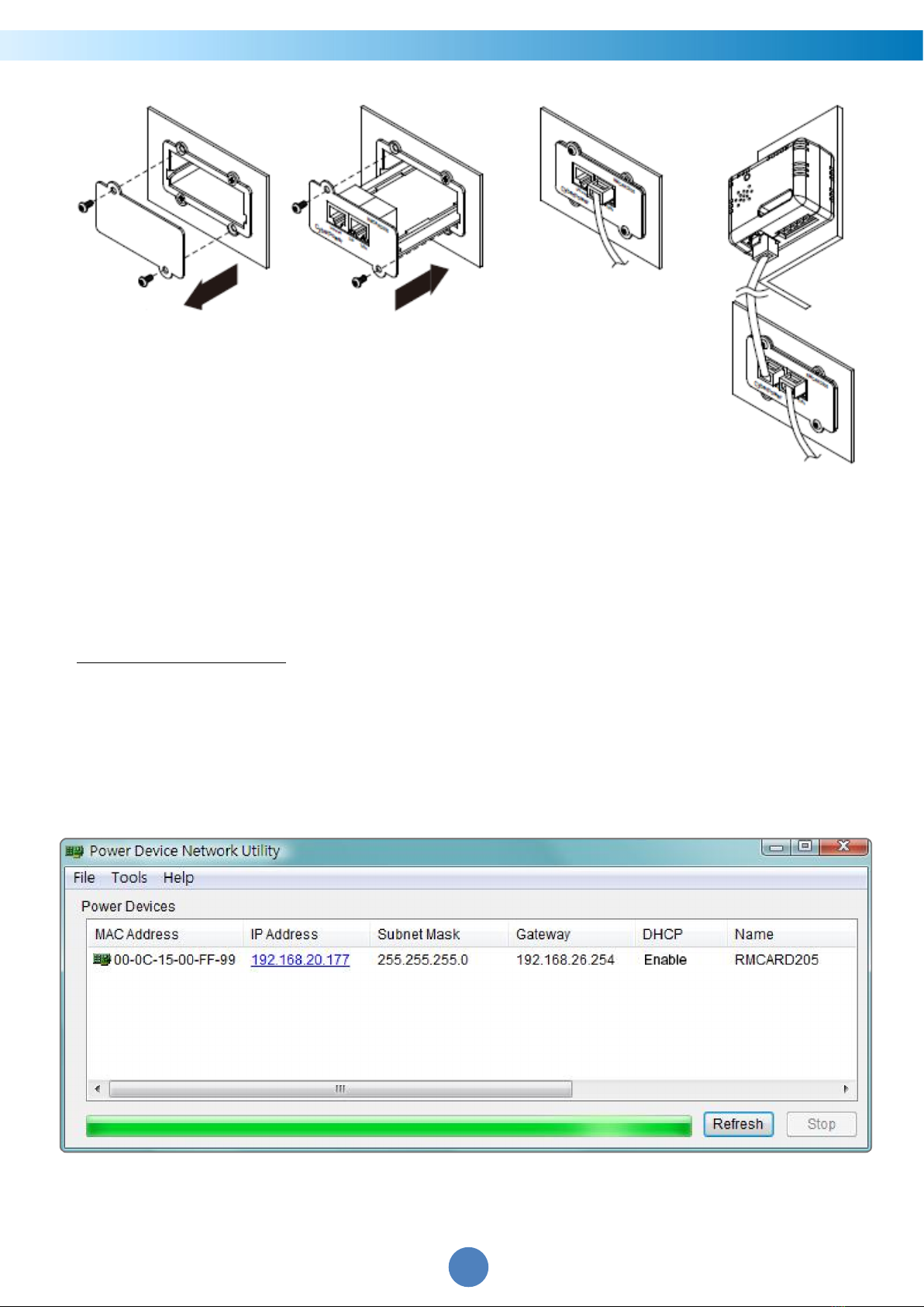
management of a UPS attached to a network. After installing the hardware and
configuring an IP address, the user can access, monitor, and control the UPS from
anywhere in the world! Simply use a web browser, command line interface or SSH client to
access your UPS. Servers and workstations can be protected by the UPS utilizing
PowerPanel®Business Remote to gracefully shutdown when signaled by the Remote
Management Card.
Features
Real time UPS monitoring
Remote management and configuration of the UPS via Web Browser, NMS or
Command Line Interface (SSH and Telnet)
Local management and configuration of the UPS via serial connection
Trigger servers/workstations to shutdown during a power event to prevent data loss or
corruption
Schedule shutdown/start-up/reboot of the UPS remotely
Event logging to trace UPS operational history
Graphic data logging to analyze power conditions
Save and restore configuration settings including current UPS and ATS parameter
configuration.
Event notifications via Email, SNMP traps, Syslog, and SMS
Remote UPS Firmware Upgrade via Web Interface and FTP in Select UPS Models
Support IPv4/v6, SNMPv1/v3, HTTP/HTTPs, DHCP, NTP, DNS, SMTP, SSH, Telnet, FTP
and Syslog protocol
Support Email Secure Authentication Protocols: SSL, TLS
Support External Authentication Protocols: RADIUS, LDAP, LDAPS, Windows AD
SNMP MIB available for free download
User upgradeable firmware via FTP, CyberPower Upgrade and Configuration Utility
and Secure Copy Protocol (SCP)
Upgrade firmware and upload configuration files to multiple units at once
Multi-language user interface
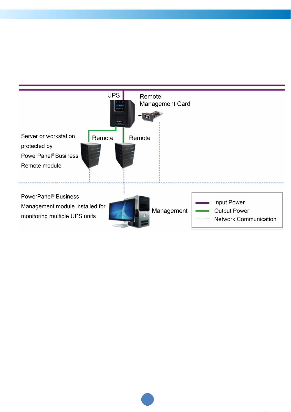
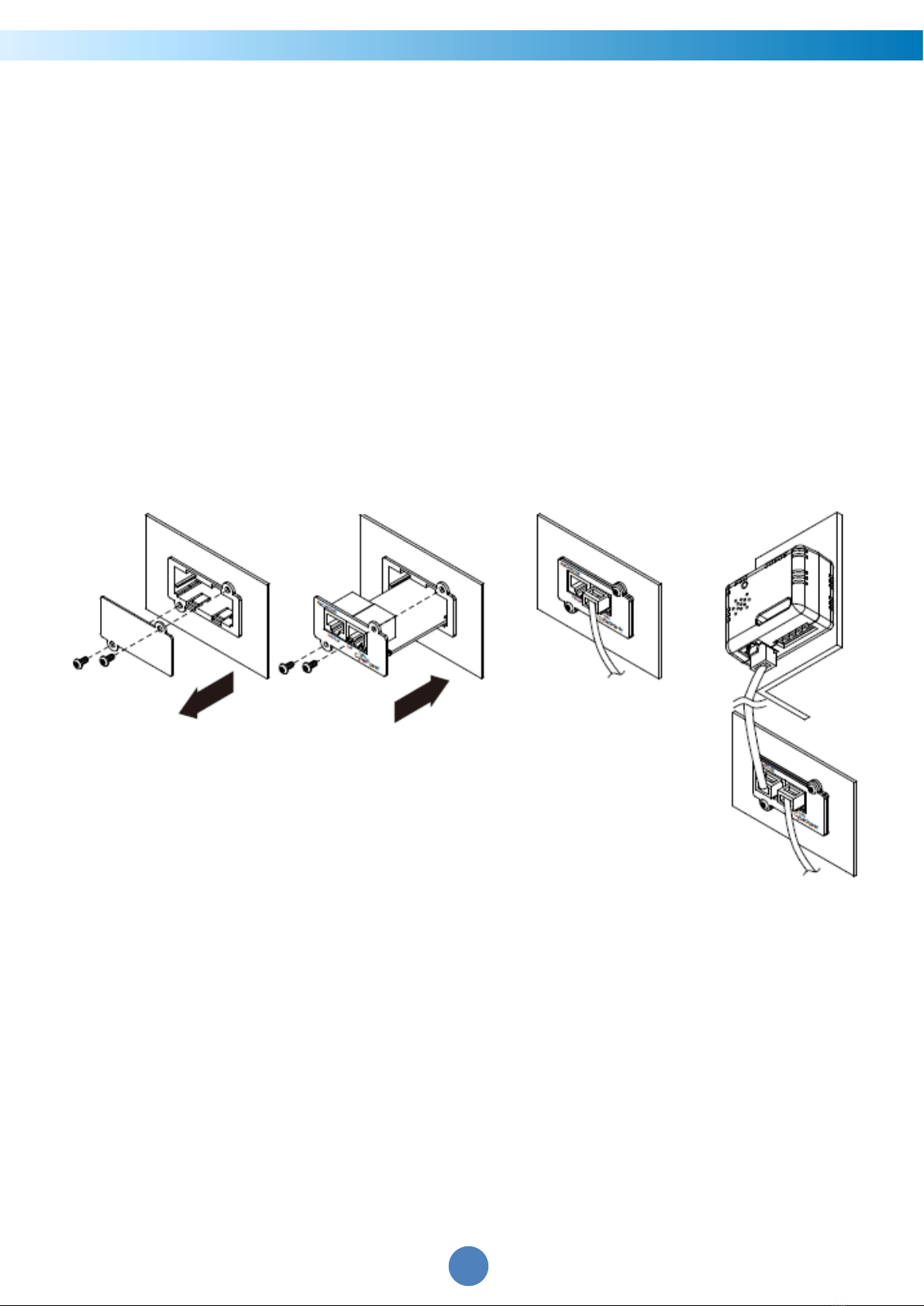
Quick installation
Hot-swappable
Cisco EnergyWise Compatible
Support Environmental Sensor (ENVIROSENSOR)

CyberPower Remote Management System
4
System Requirements
A 10/100Mbps Ethernet connection to an existing network
Web Browser or SSH client
(Optional) NMS (Network Management System) compliant with SNMP
Application with PowerPanel® Business
Unpacking
Inspect the Remote Management Card upon receipt. The package should contain the
following:
CyberPower Remote Management Card
RJ45/DB9 Serial Port Connection Cable
Quick Start Guide
Spare Jumper
RMCARD205 Front Panel (with RMCARD305 only)

CyberPower Remote Management System
5
Front Panel
RMCARD205
RMCARD305
LED Status Indicators
Link LED
Condition
Off The Remote Management Card is not connected to the
Network/ or the Remote Management Card power is off
On (Yellow) The Remote Management Card is connected to the Network
Tx/Rx LED
Off The Remote Management Card power is off
On (Green) The Remote Management Card power is on
Flashing (Green) - Receiving/transmitting data packet
- Reset finished
1. Universal Port
2. Ethernet Port
3. Tx/Rx Indicator
4. Link Indicator

CyberPower Remote Management System
6
Installation Guide
Step 1. Hardware Installation
Note: The CyberPower Remote Management Card is hot-swappable, so you do not need
to turn off the UPS to install it.
1. Remove the two retaining screws from the expansion slot and remove the cover.
2. Install the CyberPower Remote Management Card into the expansion slot.
3. Insert and tighten the retaining screws.
4. Connect an Ethernet cable to the Ethernet port of the CyberPower Remote
Management Card.
5. (Optional) To connect an environmental sensor, use a RJ45 Ethernet cable. Connect
one end to the Universal port on the RMCARD and the other end into the sensor. For
more information, please see the ENVIROSENOR user’s manual.
RMCARD205

CyberPower Remote Management System
7
Step 2. Configure the IP address for the CyberPower Remote Management
Card
Note: These instructions are for Windows OS. For other OS please refer to Appendix 4.
Method 1: Using the Power Device Network Utility
1. Install the Power Device Network Utility available for download at
www.cyberpower.com.
2. After installation completes, run the “Power Device Network Utility”.
3. The main window of the Power Device Network Utility program is shown in Figure 1.
The configuration tool will display all CyberPower Remote Management devices
present on the local network subnet. The "Refresh" button is used to search the local
network subnet again.
Figure 1. The main window of the “Power Device Network Utility” program.
4. Select the Remote Management Card you are setting up. Click on the Tools menu and
RMCARD305

CyberPower Remote Management System
8
select “Device Setup” or double click the device you want to configure.
5. You can modify the IP Address, Subnet Mask, and Gateway address for the Device MAC
Address listed in the Device Network Settings window, as shown in Figure 2. The
factory default IP Address is 192.168.20.177 and the default Subnet Mask is
255.255.255.0.
Figure 2. The Device Network setting window.
6. Modify the IP, subnet mask or gateway address. Enter the new addresses into the
corresponding fields and then click “Save”.
7. You will need to enter a User Name and Password for the Remote Management Card in
the authentication window, as shown in Figure 3.
- Default user name: cyber
- Default password: cyber
Figure 3. Authentication window.

CyberPower Remote Management System
9
8. If the IP address change is successful, you will see a message confirming the IP set up is
OK, as shown in Figure 4.
Figure 4. Setup IP Address successfully message.
9. In case the change is not successful, for example, if the IP address change is
unsuccessful you will see a warning message. Attempt to make the desired changes
again. If the problem persists please see the Troubleshooting section for help.
Method 2: Using a command prompt
1. Obtain the MAC address from the label on the Remote Management Card. Each
Management Card has a unique MAC address.
Note: The MAC address is labelled on the card.
2. Use the ARP command to set the IP address.
Example:
To assign the IP Address 192.168.10.134 for the Remote Management Card, which has a
MAC address of 00-0C-15-00-FF-99 you will type in the following in the command
prompt from a PC connected to the same network as the Remote Management Card.
(1) Type in “arp -s 192.168.10.134 00-0C-15-00-FF-99” for Windows OS; type in ”arp –s
192.168.10.134 00:0c:15:00:ff:99”for Mac OS, then press Enter.
3. Use the Ping command to assign a size of 123 bytes to the IP.
(1) Type in “ping 192.168.10.134 -l 123” then press Enter.
(2) If the replies are received, your computer can communicate with the IP address.
To select an available IP address for the Remote Management Card, please refer to
Appendix 1.

CyberPower Remote Management System
10
Web Interface
Login User Account
You will need to enter a User Name and Password to login to the interface, and can select
a preferred language after login. There are two user account types.
1. Administrator
- Default user name: cyber
- Default password: cyber
2. View only
- Default username: device
- Default password: cyber
You will be asked to reset a username and password upon the first login. The
administrator can access all functions, including enable/disable the view only account.
The viewer can access read only features but cannot change any settings.
Note: 1. The Administrator account is also used for the FTP login, Power Device Network
Utility, and Upgrade and Configuration Utility.
2. Only one user can log in and access the device at a time.
Web Content
Note: English is the default language and you can change to a preferred language.
[Summary] Provide an overview of the system operation and the items that are auto
refreshed; however, different UPS system models may have different items displayed.
Item
Definition
Current Condition Display the current operating condition of the UPS and
environmental sensor.
UPS Status
Battery Capacity Graph of the percentage of the current UPS battery capacity.
Load Graph of the load of UPS as a percentage of available Watts.
Remaining Runtime
Length of time the UPS can support its load on battery power.
System Data
Name The name given to the UPS.
Location Location description given to the UPS.
Contact The person to contact about this UPS.
Uptime. Length of time the system has been working continuously
Envir Status
Temperature Graph of the current temperature reading of the environmental
sensor.
Humidity Graph of the current humidity reading of the environmental
sensor.

CyberPower Remote Management System
11
Item
Definition
Envir Data
Name The name of the environmental sensor.
Location The location of the environmental sensor.
Recent Device Events A list of the five most recent device events. All events are related
to configuration changes.
[UPS] The following items can be displayed/configured through the UPS page; however,
different UPS models may have different items displayed/configured.
[UPS->Status] Display the basic information about the current UPS status. Items
displayed are auto refreshed.
Item
Definition
Input
Status The current status of the utility power supplied to the UPS.
Voltage
The current input voltage of the utility power supplied to the
UPS.
Frequency The current frequency of the utility power supplied to the UPS.
Bypass
Status Displays the present status of bypass circuit.
Voltage The voltage of the bypass supplied to the UPS.
Frequency The frequency of the bypass supplied to the UPS.
Current The current of the bypass supplied to the UPS.
Power Factor The ratio of the real power flowing to the bypass, to the
apparent power of bypass.
Output
Status The current status of the output power the UPS is supplying to
connected equipment.
Voltage The output voltage the UPS is supplying to the connected
equipment.
Frequency The output frequency the UPS is supplying to the connected
equipment.
Load
The power draw of the connected equipment expressed as a
percentage of the total UPS load capacity and displayed as
watts.
Current The output current the UPS is supplying to the connected
equipment.
Power Factor The radio of the active power flowing to the load, to the
apparent power in the circuit.
Active Power The capacity of the circuit for performing work in a particular
time.

CyberPower Remote Management System
12
Item
Definition
Apparent Power The product of the current and voltage of the circuit.
Reactive Power
The portion of power flow that is temporarily stored in the
form of magnetic or electric fields, due to inductive and
capacitive network elements, and then returned to source, is
known as reactive power.
Non-Critical Load
(NCL)
The present status of NCL outlets.
Energy Device energy meter reading in units of kWh.
Battery
Status The present status of the UPS battery.
Charge Mode
SBM Mode :
Using Smart Battery Management(SBM) mode to
charge the batteries , which helps extend overall battery life, and
Fast Charge Technology.
Normal Mode :
Using normal charge method to charge the
batteries.
Charge Check
In SBM Mode :
Displays the 3 operation stages (Charge Float
Rest Mode) of Smart Battery Management (SBM).
In Normal Mode :
Displays charger work in Normal Mode.
Remaining Capacity The present capacity of the batteries, expressed as a
percentage of full charge.
Remaining Runtime The amount of estimated time that the UPS can supply power to
its load.
Voltage The present voltage of the UPS battery.
System
Status The present operating status of the UPS.
Temperature The operating temperature of the UPS.
Maintenance Breaker Displays the present operating status of maintenance break.
[UPS->Battery Status] Display the information of the built-in battery and the Extended
Battery Modules (EBM) including battery pack temperature, voltage of each battery
within its pack and battery pack equalization status.
Item
Definition
Last Update Date
The last date that the battery status is updated.
Update
:Use this function to get the latest battery status.
Pack The current number of UPS/EBM battery pack.
Temperature The current temperature reading of UPS/EBM battery pack.
Voltage The current voltage reading of each UPS/EBM battery.

CyberPower Remote Management System
13
Item
Definition
Equalization Status
Display the current battery voltage equalization status of
UPS/EBM battery pack.
Active:
The battery pack equalization function is active.
Inactive:
The battery pack equalization function is not active.
[UPS->Information] Display the technical specifications of the UPS.
Information
Description
Model
The model name of the UPS.
Serial Number The serial number of the UPS.
Voltage Rating
The nominal output voltage rating (Volts) of the UPS.
Working Frequency
The operating frequency of the UPS output power.
Power Rating
The Volt-Amp rating of the UPS.
Current Rating
The output current rating (Amps) of the UPS.
Load Power The power rating (Watts) of the UPS.
Battery Voltage Rating
The operating DC voltage rating of the battery power.
Firmware Version
The revision number of the UPS firmware.
Update
:Use this function to upgrade the UPS firmware. For
further information, please refer to Appendix 3.
USB Firmware Version The revision number of the UPS USB firmware
LCD Firmware Version The revision number of the UPS LCD firmware
Battery Replacement
Date
The date that the batteries were last replaced. This must be set
manually after the batteries have been replaced or when the unit
is first installed. If this date has not been set, it is recommended
that it be set immediately.
NCL Bank The amount of Non-Critical Load banks.
Extended Battery
Modules
The amount of the external battery modules connected to the
UPS. The number of modules is configured manually, and the
configurations will vary by model.
Installation Place
When clicking the “Find it” button, either the alarm will beep or
the indicators will flash on the UPS to alert users of the specific
location. This helps users to identify a specific UPS in a multiple
UPS installation.

CyberPower Remote Management System
14
[UPS->Configuration] Configure the parameters of the UPS.
Item
Definition
Supplied Power
Voltage Set the UPS output voltage that is supplied to the connected
equipment.
Utility Power Failure Condition
Utility Sensitivity
When the UPS detects the utility voltage is out of range, the UPS
will switch to battery mode to protect the equipment plugged
into the UPS. Low sensitivity has a looser voltage range and the
supplied power may vary more widely. The power from fuel
generator may cause the UPS to switch to battery mode more
frequently, and the low sensitivity is recommended. The UPS
switches to battery mode rarely and also saves more battery
power. High sensitivity allows the UPS to supply more stable
power to equipment and switches to battery mode frequently.
High/Low Input (or
Output) Voltage
Threshold
When the utility power voltage or output voltage (depending on
UPS model) is higher/lower than the threshold, the UPS will
supply battery power to the connected equipment.
Frequency Tolerance
Sets the acceptable range of the input frequency. The UPS will
supply battery power to the connected equipment if it is out of
tolerance.
Operation
Normal
Normal operating mode of the UPS.
Generator Mode If the UPS uses generator as its input power, this option should
enable the UPS to function normally. If this option is selected, the
UPS will be forbidden to enter Bypass Mode or ECO Mode to
protect the connected equipment.
ECO Mode Economy mode. The UPS will enter Bypass Mode when the input
voltage/frequency is within the configured threshold. Once the
utility voltage/frequency exceeds thresholds, the UPS will switch
to Normal operation. This mode will significantly increase UPS
system efficiency.
Manual Bypass Determines whether to allow the UPS to enter Manual Bypass
Mode. If this option is enabled, the UPS will be forced to enter
Bypass Mode.

CyberPower Remote Management System
15
Item
Definition
Bypass Note: The UPS may automatically enter Bypass Mode per these
configured settings.
Bypass Condition
No Bypass: If this option is selected, the UPS will not enter
Bypass Mode and will stop supplying output power.
Check Volt/Freq: If the utility voltage is in the range of the
voltage thresholds and the utility frequency is in range of the
frequency tolerance, the UPS will enter Bypass Mode. Otherwise
the UPS will stop supplying output power.
Check Volt Only: Only if the utility voltage is in the range of the
voltage thresholds, the UPS will enter Bypass Mode. Otherwise
the UPS will stop supplying output power.
Bypass When UPS
Off
When the UPS turn off, the UPS switch to Bypass Mode.
Power Restore
After utility power is restored, the UPS turns on automatically
and supplies power to the connected equipment. The following
settings are used to configure the UPS restore behavior:
Automatic Restore
When this option is enabled, the UPS will restore output
immediately when the utility power restores. When this option is
disabled, the UPS will not restore output until it is turned on
manually at a later time.
Recharged Delay When utility power restores, the UPS will start to recharge until
the specified time has elapsed before restoring output power.
Recharged Capacity
When utility power restores, the UPS will start to recharge until
the specified battery capacity is met before restoring output
power.
Returned Delay The Returned Delay will take effect every time when the UPS is
turned on.
Line Stable Delay
When the UPS is in Battery Mode and utility power is restored,
the UPS will wait for the specific delay time to change Battery
Mode to Line Mode. When the UPS battery is lower than the Low
Battery Threshold and utility power is restored, the UPS will
return to Line Mode immediately.
Battery
External Battery Set Number of parallel sets and the battery capacity.
Low Battery
Threshold
When the UPS supplies battery power and the remaining
capacity is lower than this threshold, the UPS will sound an alarm.
External Battery
Modules
Set the amount of external battery modules. This allows for an
accurate runtime estimation based upon the total number of
batteries connected to the UPS.

CyberPower Remote Management System
16
Item
Definition
Periodical Battery
Test
The UPS will cyclically perform the battery test automatically to
ensure the batteries have full functional.
Note: Only Online (OL) series support the Smart Battery
Management (SBM) feature. SBM carries out battery tests,
even if Periodical Battery Test setting is disabled.
Charge Mode
Normal Mode :
Using normal charge method to charge the
batteries.
SBM Mode :
Activating the Smart Battery Management to charge
the batteries.
Charge Check Sets Enabled/Disabled to constantly monitor the charger
function.
Self Test On UPS
Startup
When this option is enabled, the UPS will perform the self test
automatically when the UPS is turned on.
Note: The self test will not be triggered when the UPS is having
an Auto-Restart.
System
Cold Start
Set the ability of the UPS to start in the absence of input power.
When this option is enabled, the UPS can be turned on with
battery power.
Audible Alarm
If this option is enabled, the UPS will issue an audible alarm when
supplying battery power, when output is overloaded, or other
conditions are present (varies by UPS model).
Dry Relay Function
This configures the UPS dry relay to function when the selected
condition occurs. Refer to the UPS manual for further
information about advanced UPS dry relay functions. The Dry
Relay Function can be configured to be activated under the
following power conditions:
(1) Utility Failure: The utility power fails and the UPS is using
battery power.
(2) Low Battery: The battery capacity is too low to support the
connected computers to shut down.
(3) Alarm: The UPS is issuing the audible alarm due to the
occurrence of warning events, such as overload.
(4) Bypass: The UPS has switched to Bypass Mode.
(5) UPS Fault: The UPS could be malfunctioning due to
hardware fault.
Screen Save Time When no UPS button is pressed and no power event occurs
during this time, the LCD screen will go to sleep.

CyberPower Remote Management System
17
Item
Definition
Enter Sleep Mode
After All Remote
Shutdown
If this option is enabled, the UPS will enter sleep mode after all
PowerPanel® Remote shundown +2 minutes.
Note: For PowerPanel® Business Edition Clients, if this option is
enabled, the UPS will enter sleep mode after utility power fails
and remaining MSDT+2 minutes. For more information about
MSDT please reference the help page in UPS -> PowerPanel List.
Wiring Fault Detecting
If this option is enabled, the UPS will detect if the input wiring is
not grounded or is reversed. It is recommended to insure the
UPS wiring has a ground connection first.
Over Discharge
Protection
When the UPS is in Battery Mode with 0% for the time
configured, the RMCARD will switch the UPS to Sleep Mode and
the output will be turned off.
Non-Critical Outlet Bank
Turn Off Threshold
When supplying battery power, the UPS will power off this NCL
outlet bank if the remaining battery capacity is lower than this
threshold.
Turn off Delay When supplying battery power, the UPS will power off this NCL
outlet bank after this delay time is met.
Turn On Delay
When utility power is restored, the UPS will restore the output of
this NCL outlet bank after the delay time is met. This prevents
excessive power consumption caused by all the connected
equipment starting at the same time.

CyberPower Remote Management System
18
[UPS->Master Switch] Switch the output power of the UPS to be on or off.
Item
Definition
Reboot UPS
Turns the UPS off and back on
Turn UPS Off
Turns the UPS off.
UPS Sleep
This command is available in Utility Power Failure Mode. It puts
the UPS in sleep mode until power is restored.
Note: Some UPS models may not support this command.
Reset
Resets the pending action to turn the UPS off.
Turn UPS On
Turns the UPS on.
Shutdown/Sleep Delay Amount of time the UPS waits before it turns off in response to
a "Reboot UPS", "Turn UPS off" or "UPS Sleep" command.
Reboot Duration
After the UPS is turned off, Reboot Duration defines how long
the UPS waits before it turns back on response to "Reboot UPS"
command.
Signal PowerPanel®
Remote to Shutdown
Select this option to warn PowerPanel
®
Business Remote before
turning the UPS off. The Shutdown Delay (MST, Max Clients
Shutdown Time) for the UPS can be changed to insure a
graceful shutdown.
[UPS->Bank Control] Display the current state of each outlet Bank, and it provides
on/off control for the Critical/Non-Critical Outlet Bank. Outlet Number and Device Name
displays the device name associated with the specific outlet.
Item
Definition
Bank Control Options
ON Turns critical/non-critical bank on immediately.
OFF Turns critical/non-critical bank off immediately.
Device Name Identification
Outlet #
UPS outlet number as designated by the outlet configuration
(varies by UPS model).
Device Name Device Name assigned to this outlet.
Note: Only Critical Outlet Bank switchable UPS support on/off control for the Critical
Outlet Bank.

CyberPower Remote Management System
19
[UPS->Diagnostics] The UPS/Diagnostics page provides the ability to verify UPS
batteries are in adequate working conditions. You can also complete a runtime
calibration to insure an accurate estimation for the connected load.
Item
Definition
Battery Test
The
Battery Test
will force the UPS to switch to battery power
for 10 seconds. This allows the user to verify the battery
conditions and provides information about the battery,
including the results and date of the last battery test. Click the
“
Start
”
button to begin a battery test. The information will be
reported after a battery test completes.
Note: “N/A” means the UPS model does not have this function.
Last Test Result
The results of the most recent battery test.
Passed
:The battery performed normally during the test.
Failed
:The battery test did not pass.
Follow the steps below if the battery test fails:
Repeat the battery test and replace the batteries if the test fails
again.
Contact
CyberPower
for assistance if the battery test fails after
the batteries have been replaced.
Last Test Date The date of the most recent battery test.
Runtime Estimation
The Runtime Estimation function discharges the UPS batteries
from the battery capacity, at the time the estimate is requested,
to near zero capacity with the current load. The results of the
runtime estimation show the runtime, status of estimation, and
the date of the last estimation. When the runtime estimation is
initiated, the connected
equipment will be run on battery power until the batteries are
discharged to near zero capacity. Once the batteries are
discharged to this point, the connected equipment will run on
utility power. The
Runtime Estimation
batteries will then be recharged automatically after the
estimation is done.
Note: This estimated runtime may vary based on the load and
the level of charge on the batteries when the runtime estimation
is initiated. The batteries will be recharged then automatically
after the estimation is done.
Users can click the “Start” button to initiate the runtime
estimation. Click the “Abort” button to interrupt the runtime
estimation. The result will be reported after the runtime
estimation is finished or canceled
Estimated Runtime The estimated runtime of the batteries with the current load.

CyberPower Remote Management System
20
Item
Definition
Last Estimation Result
The results of the last Runtime Estimation.
Passed
:The runtime estimation was completed and the
batteries are good.
Canceled
: The runtime estimation was interrupted.
Last Estimation Date The date the last runtime estimation was performed.
[UPS->Schedule]: Sets the UPS to automatically shutdown and restart at scheduled
times (Once/Daily/Weekly). The Schedule page manages scheduled shutdowns and lists
all configured schedules. Each schedule row displays the details of when the schedule will
take effect.
[Once]: The user may set one time event for the UPS to shutdown/restart.
[Daily]: Set a daily re-occurrence for the UPS to shutdown/restart.
[Weekly]: Set a weekly re-occurrence for the UPS to shutdown/restart.
1. Click [Once], [Daily] or [Weekly] option and Click “Next>>”, Enter the date and time to
shut down the UPS. Select [Never], [Instant], or the date and time for the UPS to turn
back on. Select the bank to be controlled, and click “Shutdown Clients” to set all clients
to perform a graceful shutdown. You can enter a “Name” for this Schedule.
2. Click “Apply” to add the item to the Schedule. Click “Reset” to return to default
settings..
3. Saved settings are listed in [Schedule] menu.
4. If you want to delete the scheduled action, simply click the Name of the item listed in
[Schedule] menu, and click “Delete”.
Note: The management system allows up to 10 schedule entries.
[UPS->Wake on Lan] This function is used to wake a computer through the network.
Enter the IP address of that computer when it is on and the system will search its MAC
address accordingly. The maximum number of IP addresses that can be set is 50.
Item
Definition
PowerPanel
®
Remote
Load/Sync with
PowerPanel®Remote
List
Enable this option to Load and Synchronize WoL Client List with
PowerPanel® Remote List.
Wake Conditions
UPS Turn On
When selected, this option will enable the RMCARD to send the
WoL signal to the connected PowerPanel® Remote computers
when the UPS turns on.
Other manuals for RMCARD205
4
This manual suits for next models
1
Table of contents
Other CyberPower Adapter manuals
Popular Adapter manuals by other brands

Acksys
Acksys MI400 Series Technical documentation

Emulex
Emulex LP9002S Installation and reference manual

ZyXEL Communications
ZyXEL Communications AG-220 Declaration of conformity

Handheld Scientific
Handheld Scientific BT-500 user manual

D-Link
D-Link AirPlusXtremeG DWL-G650 Quick installation guide

Panda Wireless
Panda Wireless PBU40 quick start guide