CYP CMX-12 User manual

Operation Manual
Operation Manual
CMX-12
HD/SD Digital AV Mixer


DISCLAIMERS
The information in this manual has been carefully checked and is believed to be accurate. Cypress
Technology assumes no responsibility for any infringements of patents or other rights of third parties
which may result from its use.
Cypress Technology assumes no responsibility for any inaccuracies that may be contained in this
document. Cypress also makes no commitment to update or to keep current the information
contained in this document.
Cypress Technology reserves the right to make improvements to this document and/or product at
any time and without notice.
COPYRIGHT NOTICE
No part of this document may be reproduced, transmitted, transcribed, stored in a retrieval system,
or any of its part translated into any language or computer le, in any form or by any means—
electronic, mechanical, magnetic, optical, chemical, manual, or otherwise—without express written
permission and consent from Cypress Technology.
© Copyright 2011 by Cypress Technology.
All Rights Reserved.
Version 1.1 August 2011
TRADEMARK ACKNOWLEDGMENTS
All products or service names mentioned in this document may be trademarks of the companies
with which they are associated.

SAFETY PRECAUTIONS
Please read all instructions before attempting to unpack, install or operate this equipment and
before connecting the power supply.
Please keep the following in mind as you unpack and install this equipment:
• Always follow basic safety precautions to reduce the risk of re, electrical shock and injury to
persons.
• To prevent re or shock hazard, do not expose the unit to rain, moisture or install this product
near water.
• Never spill liquid of any kind on or into this product.
• Never push an object of any kind into this product through any openings or empty slots in the
unit, as you may damage parts inside the unit.
• Do not attach the power supply cabling to building surfaces.
• Use only the supplied power supply unit (PSU). Do not use the PSU if it is damaged.
• Do not allow anything to rest on the power cabling or allow any weight to be placed upon it or
any person walk on it.
• To protect the unit from overheating, do not block any vents or openings in the unit housing that
provide ventilation and allow for sufcient space for air to circulate around the unit.
REVISION HISTORY
VERSION NO. DATE DD/MM/YY SUMMARY OF CHANGE
VS1 25/11/11 First release

CONTENTS 1. Introduction............................................................................1
2. Applications...........................................................................1
3. Package Contents ................................................................1
4. System Requirements............................................................1
5. Features..................................................................................1
6. Operation Controls and Functions.......................................2
6.1 Position/Time ..................................................................... 2
6.2 Wipe Modes ......................................................................3
6.3 Mode Control....................................................................4
6.4 Digital Effects ....................................................................5
6.5 Adjust .................................................................................6
6.6 Video Source Select.........................................................7
6.7 Audio/Video Mixer ........................................................... 8
6.8 Audio Level .......................................................................9
6.9 Rear Panel....................................................................... 10
7. Operation .............................................................................11
7.1 Basic Operation..............................................................11
7.2 Input Signal Selection and Back Color Selection .......11
7.3 Video Mix.........................................................................12
7.4 Video Wipe .....................................................................12
7.5 WIPE PATTERN Selection................................................. 13
7.6 Multiple Pattern Selection .............................................14
7.7 ONE-WAY WIPE ...............................................................14
7.8 REVERSE WIPE ..................................................................14
7.9 Picture-In-Picture ............................................................ 15
7.10 KEY..................................................................................16
7.11 AUTO FADE/WIPE Selection .........................................17
7.12 DIGITAL EFFECT..............................................................17
7.13 AUDIO MIXER................................................................. 17
7.14 OSD ADJUST ..................................................................18
8. Connector and Installation.................................................19
8.1 Front Panel Connections ............................................... 19
8.2 Rear Panel Connections................................................19
8.3 Output Resolutions .........................................................19
9. Specications ......................................................................20

1
1. INTRODUCTION
The CMX-12 is a high-quality Standard and High Dention
Digital Audio/Video Mixer. Each input BUS supports up to
6 inputs (2×HDMI, 2×Component (SD/HD), 2×S-Video and
Composite video). Effects can be added such as wipes,
fades, mixes and speacial digital effects.
The CMX-12 can support HD or SD resolutions (480p,
576p, 720p 50/60, 1080i 50/60), most of the worlds video
standards (NTSC, NTSC-4.43, PAL, PAL-M, PAN-N, SECAM)
and HDMI, Component, S-Video or Composite video
outputs, it also supports position adjustment and recording.
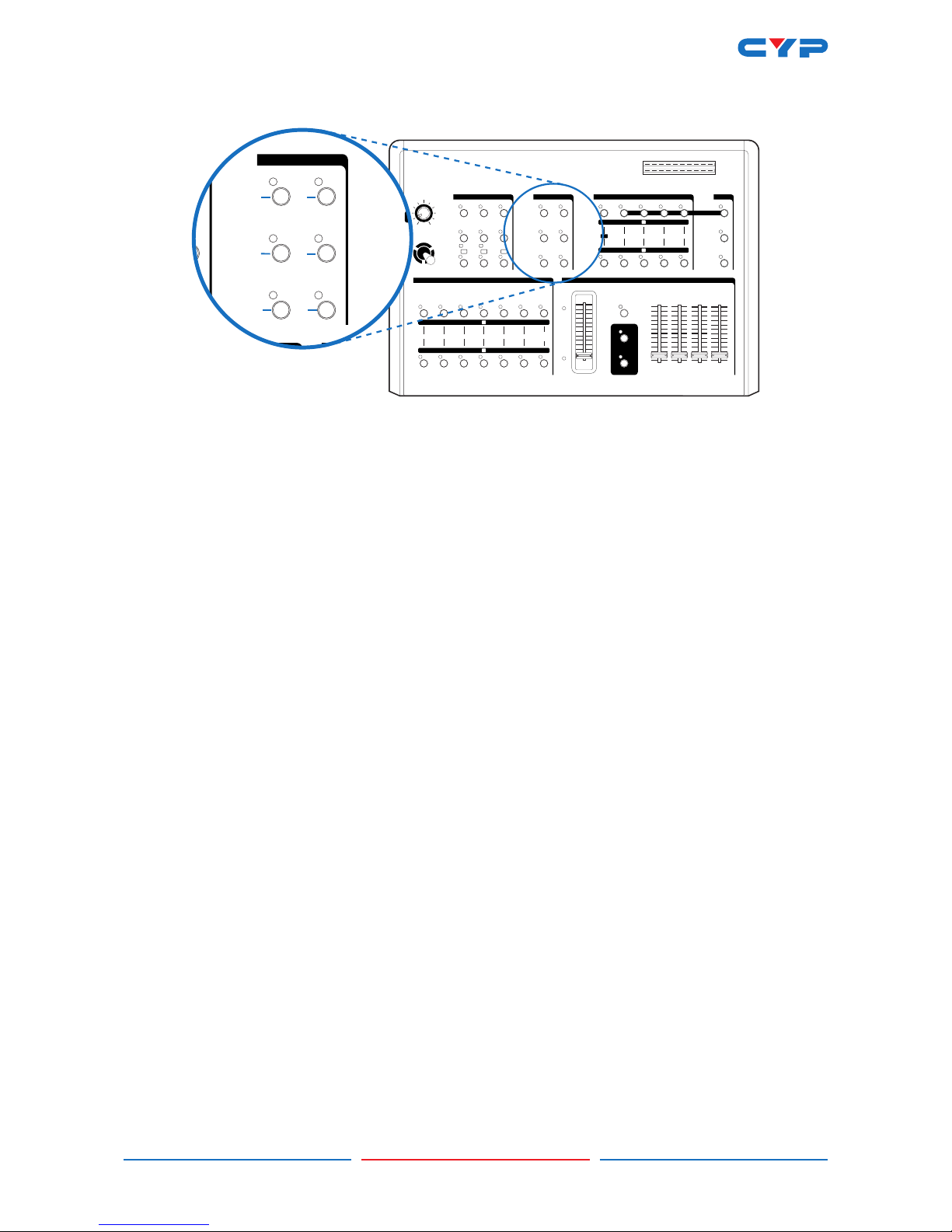
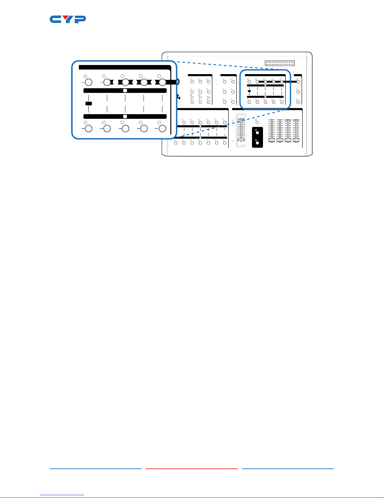
The output resolution can automatically adjust to input resolution or be manually adjusted (please
refer to the diagram above).
2. APPLICATIONS
• Amatuer/Professional Video and Audio Mixing.
3. PACKAGE CONTENTS
• CMX-12 SD/HD Video and Audio Mixer.
• Cable Pack: 1× HDMI Cable/1× S-Video Cable/1× Stereo Audio and Composite Video Cable/1×
Stereo Audio to 3.5 mm Jack cable/1× Component (YPbPr) Cable.
• 1× Metal Joystick (screw attchment) for Position control.
• 12 V/5.0A DC power adaptor.
• User Manual.
4. SYSTEM REQUIREMENTS
HDMI (Non-HDCP), HD (YPbPr) or SD (Composite or S-Video) Source.
HDMI (Non-HDCP), HD (YPbPr) or SD (Composite or S-Video) Recording Device.
HDMI (Non-HDCP), HD (YPbPr) or SD (Composite or S-Video) Monitor or display.
5. FEATURES
• Selective size and position for digital effects area and PIP windows.
• Automatic fade and wipe with speed preset control.
• Digital effects- Still,Mosaic,Paint and Negative.
• 96 wipe patterns.
• Chroma key & Luminance key.
• High Picture Quality.
• 3×8 back color.
• Joystick control for digital effect position.
• Fade control for Video and Audio.
• Video and Audio mixing.
• 2× HDMI source inputs.
• 2× Component (YPbPr) source inputs.
• 2× Composite and S-Video source inputs.
• 1× HDMI recording output.
• 2× Component (YPbPr) recording outputs.
• 1× Composite and S-Video recording outputs.
• 1× Composite and S-Video preview outputs with On-screen Display.
• Auxiliary audio input.
INPUT OUTPUT
Digital video--480i,576i,480p,576p,720p50,720p60,1080i50,1080i60
Analog video--NTSC,NTSC4.43,PAL,PAL-M,PAL-N,SECAM
Analog video--480i,576i,480p,576p,720p50,720p60,1080i50,1080i60
S-Video
Component
Composite
HDMI
S-Video
Component
Composite
HDMI

2
• Microphone input and headphone output.
• Picture in Picture control (3 window sizes).
• Each A/B BUS can adjust the Contrast/Brightness/Color/Hue/Detail and Aspect Ratio.
• Supports Lip-Sync delay up to 170 ms.
• Composite supports 3D comb lter and YC separation.
• Motion and Edge Adaptive De-interlacing.
Note: When the selected source input is not connected or has HDCP protection, only a black
screen will be displayed.
6. OPERATION CONTROLS AND FUNCTIONS
6.1 Position/Time
MAX
MIN
AUDIO FOLLOW
AUTO / WIPE
START
ON
-15
L
AUDIO
LEVEL R
DB
DB
-10 -5 -3 +3 +4+20+1-1
-15 -10 -5 -3 +3 +4+20+1-1
INPUT A
MAX
MIN
INPUT B
MAX
MIN
AUX
MAX
MIN
MIC
MAX
MIN
VIDEO
VIDEO/AUDIO MIXERVIDEO SOURCE SELECT
BACK
COLOR
SD INPUT 2SD INPUT 1HD INPUT 2HD INPUT 1HDMI 2HDMI 1
DIGITAL EFFECTS ADJUSTFUNCTIONS MODE CONTROL
KEYMIX1/41/31/2
PIP
COLOR
WIPE
EDGE
MULTIREVERSEONE-WAY
B-KEY 1/2L-KEY 1/2
1/2 1/3 1/4
A SOURCE B SOURCE
STILL
TIME
POSITION
MIN MAX DEMO
ADJUST
SCAN
NEGATIVEPAINT MOSAIC
B
A
A
B
ON
HD AV EFFECTS PROCESSOR
FUNC
1/
ONE-
L-KE
1/
A S
TIME
POSITION
MIN MAX
➊
➋
➊Time Control
For adjusting the transition time of the Auto Fade and the Auto Wipe functions.
➋ Joystick control
The joystick control has two functions, it controls the position of the 'Shape' wipe pattern (button
⓫) and the on-screen location of the picture-in-picture box (button ⓭).

3
6.2 Wipe Modes
MAX
MIN
AUDIO FOLLOW
AUTO / WIPE
START
ON
-15
L
AUDIO
LEVEL R
DB
DB
-10 -5 -3 +3 +4+20+1-1
-15 -10 -5 -3 +3 +4+20+1-1
INPUT A
MAX
MIN
INPUT B
MAX
MIN
AUX
MAX
MIN
MIC
MAX
MIN
VIDEO
VIDEO/AUDIO MIXERVIDEO SOURCE SELECT
BACK
COLOR
SD INPUT 2SD INPUT 1HD INPUT 2HD INPUT 1HDMI 2HDMI 1
DIGITAL EFFECTS ADJUSTFUNCTIONS MODE CONTROL
KEYMIX1/41/31/2
PIP
COLOR
WIPE
EDGE
MULTIREVERSEONE-WAY
B-KEY 1/2L-KEY 1/2
1/2 1/3 1/4
A SOURCE B SOURCE
STILL
TIME
POSITION
MIN MAX DEMO
ADJUST
SCAN
NEGATIVEPAINT MOSAIC
B
A
A
B
ON
HD AV EFFECTS PROCESSOR
URCE SELECT
FUNCTIONS
1/41/31/2
MULTIREVERSEONE-WAY
B-KEY 1/2L-KEY 1/2
1/2 1/3 1/4
A SOURCE B SOURCE
X
VIDEO EFFECTS MIXER
➍➌ ➎
➐➏ ➑
➓➒ ⓫
➌One-way wipe button
Selects the standard direction for the wipe pattern.
➍Reverse wipe button
Selects the reverse direction for the wipe pattern.
➎Multiple wipe button
Adds multiple wipes to the wipe pattern (up to 4 wipes).
➏Straight wipe button
Selects and toggles between 4 straight vertical or horizontal wipe patterns.
➐Split wipe button
Selects and toggles between 4 split wipe patterns.
➑Corner wipe button
Selects and toggles between 4 wipe patterns that originate from a corner.
➒Diagonal wipe button
Selects and toggles between diagonal style wipe patterns.
➓Triangle wipe button
Selects and toggles between triangle style wipe patterns.
⓫Shape wipe button
Selects and toggles between 4 differently shaped wipes patterns (circle, oval, diamond and
square). The position of the wipe can be adjusted using the Position Joystick (➋)

4
6.3 Mode Control
MAX
MIN
AUDIO FOLLOW
AUTO / WIPE
START
ON
-15
L
AUDIO
LEVEL R
DB
DB
-10 -5 -3 +3 +4+20+1-1
-15 -10 -5 -3 +3 +4+20+1-1
INPUT A
MAX
MIN
INPUT B
MAX
MIN
AUX
MAX
MIN
MIC
MAX
MIN
VIDEO
VIDEO/AUDIO MIXERVIDEO SOURCE SELECT
BACK
COLOR
SD INPUT 2SD INPUT 1HD INPUT 2HD INPUT 1HDMI 2HDMI 1
DIGITAL EFFECTS ADJUSTFUNCTIONS MODE CONTROL
KEYMIX1/41/31/2
PIP
COLOR
WIPE
EDGE
MULTIREVERSEONE-WAY
B-KEY 1/2L-KEY 1/2
1/2 1/3 1/4
A SOURCE B SOURCE
STILL
TIME
POSITION
MIN MAX DEMO
ADJUST
SCAN
NEGATIVEPAINT MOSAIC
B
A
A
B
ON
HD AV EFFECTS PROCESSOR
VIDEO/AUDIOMIXER
DIGMODE CONTROL
KEYMIX4
PIP
COLOR
WIPE
EDGE
LTI
4
⓬ ⓭
⓮ ⓯
⓰
⓬Wipe button
Selects the wipe mode.
⓭PIP button
Selects the picture-in-picture mode.
⓮Mix (Fade) button
Selects the fade in/out mode.
⓯KEY button
Selects the blue key and luma key effects mode.
⓰EDGE button
In wipe mode, toggles between sharp/soft or colored edge.
COLOR button
Toggles the edge colour when the EDGE button is set to coloured edge mode.

5
6.4 Digital Effects
MAX
MIN
AUDIO FOLLOW
AUTO / WIPE
START
ON
-15
L
AUDIO
LEVEL R
DB
DB
-10 -5 -3 +3 +4+20+1-1
-15 -10 -5 -3 +3 +4+20+1-1
INPUT A
MAX
MIN
INPUT B
MAX
MIN
AUX
MAX
MIN
MIC
MAX
MIN
VIDEO
VIDEO/AUDIO MIXERVIDEO SOURCE SELECT
BACK
COLOR
SD INPUT 2SD INPUT 1HD INPUT 2HD INPUT 1HDMI 2HDMI 1
DIGITAL EFFECTS ADJUSTFUNCTIONS MODE CONTROL
KEYMIX1/41/31/2
PIP
COLOR
WIPE
EDGE
MULTIREVERSEONE-WAY
B-KEY 1/2L-KEY 1/2
1/2 1/3 1/4
A SOURCE B SOURCE
STILL
TIME
POSITION
MIN MAX DEMO
ADJUST
SCAN
NEGATIVEPAINT MOSAIC
B
A
A
B
ON
HD AV EFFECTS PROCESSOR
DIGITAL EFFECTS
STILL NEGATIVEPAINT MOSAIC
A
B
ON
⓲ ⓳ ⓴
⓲A-bus digital effect ON button.
⓳ A-bus Still button/OSD left adjust.
⓴ A-bus Paint button/OSD right adjust.
A-bus Negative button/OSD up adjust.
A-bus Mosaic button/OSD down adjust.
B-bus digital effect ON button.
B-bus Still button.
B-bus Paint button.
B-bus Negative button.
B-bus Mosaic button.

6
6.5 Adjust
MAX
MIN
AUDIO FOLLOW
AUTO / WIPE
START
ON
-15
L
AUDIO
LEVEL R
DB
DB
-10 -5 -3 +3 +4+20+1-1
-15 -10 -5 -3 +3 +4+20+1-1
INPUT A
MAX
MIN
INPUT B
MAX
MIN
AUX
MAX
MIN
MIC
MAX
MIN
VIDEO
VIDEO/AUDIO MIXERVIDEO SOURCE SELECT
BACK
COLOR
SD INPUT 2SD INPUT 1HD INPUT 2HD INPUT 1HDMI 2HDMI 1
DIGITAL EFFECTS ADJUSTFUNCTIONS MODE CONTROL
KEYMIX1/41/31/2
PIP
COLOR
WIPE
EDGE
MULTIREVERSEONE-WAY
B-KEY 1/2L-KEY 1/2
1/2 1/3 1/4
A SOURCE B SOURCE
STILL
TIME
POSITION
MIN MAX DEMO
ADJUST
SCAN
NEGATIVEPAINT MOSAIC
B
A
A
B
ON
HD AV EFFECTS PROCESSOR
ADJUST
DEMO
ADJUST
SCAN
MOSAIC
ADJUST button
When activated, the Setup Menu is displayed through the SD Preview output. In this mode, the
menu can be navigated and values adjusted using the cursor buttons (⓳t⓴u and
p). When deactivated the SD Preview output will show A-bus/B-bus output source and format.
DEMO button
When pressed, this button places the unit into DEMO mode and will cycle through all 96 wipe
patterns. The speed of the DEMO mode can be controlled with the Time Control (➊). Press the
DEMO button again to cancel DEMO mode.
SCAN button
If the SCAN button is pressed for 3 seconds, the system will enter SCAN mode and will SCAN the
input ports from 1 to 6 and record each port's format to the system memory.

7
6.6 Video Source Select
MAX
MIN
AUDIO FOLLOW
AUTO / WIPE
START
ON
-15
L
AUDIO
LEVEL R
DB
DB
-10 -5 -3 +3 +4+20+1-1
-15 -10 -5 -3 +3 +4+20+1-1
INPUT A
MAX
MIN
INPUT B
MAX
MIN
AUX
MAX
MIN
MIC
MAX
MIN
VIDEO
VIDEO/AUDIO MIXERVIDEO SOURCE SELECT
BACK
COLOR
SD INPUT 2SD INPUT 1HD INPUT 2HD INPUT 1HDMI 2HDMI 1
DIGITAL EFFECTS ADJUSTFUNCTIONS MODE CONTROL
KEYMIX1/41/31/2
PIP
COLOR
WIPE
EDGE
MULTIREVERSEONE-WAY
B-KEY 1/2L-KEY 1/2
1/2 1/3 1/4
A SOURCE B SOURCE
STILL
TIME
POSITION
MIN MAX DEMO
ADJUST
SCAN
NEGATIVEPA INT MOSAIC
B
A
A
B
ON
HD AV EFFECTS PROCESSOR
VIDEO SOURCE SELECT
BACK
COLOR
SD INPUT 2SD INPUT 1HD INPUT 2HD INPUT 1HDMI 2HDMI 1
B
A
/ Selects Source 1, HDM I 1 for A-bus/B-bus.
/ Selects Source 2, HDMI 2 for A-bus/B-bus.
/ Selects Source 3, HD input 1 for A-bus/B-bus.
/ Selects Source 4, HD input 2 for A-bus/B-bus.
/ Selects Source 5, SD input 1 for A-bus/B-bus. When both S-Video and Composite Video
sources are connected at the same time, S-Video will be the rst source to be displayed.
/ Selects Source 5, SD input 2 for A-bus/B-bus. When both S-Video and Composite Video
sources are connected at the same time, S-Video will be the rst source to be displayed.
Selects the A-bus background color, one of eight colors can be selected.
Selects the B-bus background color, one of eight colors can be selected.

8
6.7 Audio/Video Mixer
MAX
MIN
AUDIO FOLLOW
AUTO / WIPE
START
ON
-15
L
AUDIO
LEVEL R
DB
DB
-10 -5 -3 +3 +4+20+1-1
-15 -10 -5 -3 +3 +4+20+1-1
INPUT A
MAX
MIN
INPUT B
MAX
MIN
AUX
MAX
MIN
MIC
MAX
MIN
VIDEO
VIDEO/AUDIO MIXERVIDEO SOURCE SELECT
BACK
COLOR
SD INPUT 2SD INPUT 1HD INPUT 2HD INPUT 1HDMI 2HDMI 1
DIGITAL EFFECTS ADJUSTFUNCTIONS MODE CONTROL
KEYMIX1/41/31/2
PIP
COLOR
WIPE
EDGE
MULTIREVERSEONE-WAY
B-KEY 1/2L-KEY 1/2
1/2 1/3 1/4
A SOURCE B SOURCE
STILL
TIME
POSITION
MIN MAX DEMO
ADJUST
SCAN
NEGATIVEPAINT MOSAIC
B
A
A
B
ON
HD AV EFFECTS PROCESSOR
MAX
MIN
AUDIO FOLLOW
AUTO / WIPE
START
ON
INPUT A
MAX
MIN
INPUT B
MAX
MIN
AUX
MAX
MIN
MIC
MAX
MIN
VIDEO
VIDEO/AUDIO MIXER
A-bus LED indicator/ B-bus LED indicator
Indicates which input signal is currently in use and displayed. When the Video Slider is at the
top, A-bus input signal is selected/displayed and the A-bus indicator is lit. When the Video
Slider is at the bottom, the B-bus input signal is selected/displayed and the B-bus indicator is
lit. When the Video Slider is at anypoint between, the two LEDs will ash in squence to indicate
that wipe/fade/mix is in progress.
VIDEO Slider
Controls the Wipe, PIP and Key effects. Move the slider to control the position of a wipe, the
degree of fade or mix, or the strength of a Luma key or blue key effect.
AUDIO FOLLOW
Controls manual or automatic audio mixing. When activated the audio mix between A-bus
and B-bus audio inputs is controlled by the Video Slider . When deactivated, the audio mix
between the A-bus and B-bus can be independently controlled and .
Note: AUDIO FOLLOW only affects the Input A or Input B audio mix, the AUX or MIC inputs remain
unaffected.
AUTO/WIPE
When pressed, puts the unit into AUTO/WIPE mode and disables the Video Slider.
START Button
When the start button is pressed, the most recently programmed wipe/fade/mix is initiated.
The TIME control ➊ can be used to adjust the length of the transition. The LED will be lit for the
duration of the transition and will go out when complete.
INPUT A
Controls the audio level of Input A.
INPUT B
Controls the audio level of Input B.
AUX
Controls the audio level of the Auxiliary input.
MIC
Controls the audio level of the Microphone input.

9
6.8 Audio Level
MAX
MIN
AUDIO FOLLOW
AUTO / WIPE
START
ON
-15
L
AUDIO
LEVEL R
DB
DB
-10 -5 -3 +3 +4+20+1-1
-15 -10 -5 -3 +3 +4+20+1-1
INPUT A
MAX
MIN
INPUT B
MAX
MIN
AUX
MAX
MIN
MIC
MAX
MIN
VIDEO
VIDEO/AUDIO MIXERVIDEO SOURCE SELECT
BACK
COLOR
SD INPUT 2SD INPUT 1HD INPUT 2HD INPUT 1HDMI 2HDMI 1
DIGITAL EFFECTS ADJUSTFUNCTIONS MODE CONTROL
KEYMIX1/41/31/2
PIP
COLOR
WIPE
EDGE
MULTIREVERSEONE-WAY
B-KEY 1/2L-KEY 1/2
1/2 1/3 1/4
A SOURCE B SOURCE
STILL
TIME
POSITION
MIN MAX DEMO
ADJUST
SCAN
NEGATIVEPAINT MOSAIC
B
A
A
B
ON
HD AV EFFECTS PROCESSOR
-15
L
AUDIO
LEVEL R
DB
DB
-10 -5 -3 +3 +4+20+1-1
-15 -10 -5 -3 +3 +4+20+1-1
Audio level indicator (Audio level)
This indicator shows the audio output level of REC out 1 and REC out 2.

10
6.9 Rear Panel
DC INPUT
12V
R1 R1R2 R2 RR1L1 L1L2 L2 LL1L2
Pr
Pb VS
VS
Y
R2
VSPr
Pb
Y
VSPr
Pb
Y
HDMI 1 HDMI 2
Pr
Pb
Y
AUX INPUT
SD INPUT 1
SD INPUT 2
SD AUDIO INPUTHD AUDIO INPUT
HD OUTPUT 1
HD OUTPUT 2
HD INPUT 1
HD INPUT 2
AUDIO OUTPUT
SD OUTPUT
SD PREVIEW
HDMI OUTPUTHDMI INPUT
Source 3 HD audio input 1.
Source 4 HD audio input 2.
Source 5 SD audio input 1.
Source 6 SD audio input 2.
Auxiliary Audio input Jack.
Recording out 1 Audio output Jack.
Recording out 2 Audio output Jack.
Power Switch
Source 1 HDMI input 1.
Source 2 HDMI input 2.
Source 3 HD Y-PB-PR Video input 1.
Source 4 HD Y-PB-PR Video input 2.
Source 5 SD Video and YC input 1.
Source 6 SD Video and YC input 2.
HDMI output for monitor.
Recording out 1 HD YPb-Pr Video output jack.
Recording out 2 HD YPb-Pr Video output jack.
SD PREVIEW out (OSD) Video and YC output jack.
SD Recording out Video and YC output jack.
DC INPUT 12V 3.0A.

11
7. OPERATION
7.1 Basic Operation
Turn the power switch at the rear panel to the ON Position. The LEDs on the operation panel will light
up and the unit is now in inital mode for operation.
7.2 Input Signal Selection and Back Color Selection
MAX
MIN
AUDIO FOLLOW
AUTO / WIPE
START
ON
-15
L
AUDIO
LEVEL R
DB
DB
-10 -5 -3 +3 +4+20+1-1
-15 -10 -5 -3 +3 +4+20+1-1
INPUT A
MAX
MIN
INPUT B
MAX
MIN
AUX
MAX
MIN
MIC
MAX
MIN
VIDEO
VIDEO/AUDIO MIXERVIDEO SOURCE SELECT
BACK
COLOR
SD INPUT 2SD INPUT 1HD INPUT 2HD INPUT 1HDMI 2HDMI 1
DIGITAL EFFECTS ADJUSTFUNCTIONS MODE CONTROL
KEYMIX1/41/31/2
PIP
COLOR
WIPE
EDGE
MULTIREVERSEONE-WAY
B-KEY 1/2L-KEY 1/2
1/2 1/3 1/4
A SOURCE B SOURCE
STILL
TIME
POSITION
MIN MAX DEMO
ADJUST
SCAN
NEGATIVEPAINT MOSAIC
B
A
A
B
ON
HD AV EFFECTS PROCESSOR
②
④①
③
q
Move the Video slider (Button ) to the A-bus position. The A-bus LED will turn on, B-bus LED
will turn off.
w
Select your source for A-bus from any of the Sources (HDMI 1, HDMI 2, HD Input 1, HD Input 2,
SD Input 1 or SD Input 2) and Back color button. You will see the corresponding picture on the
screen.
③
Press a Back Color button to select the background color required. Repeatedly pressing the
Back Color selection button will cycle through the available background colors (Blue, Red,
Magenta, Green, Cyan, Yellow, White or Black).
④
The same procedures apply to the B-bus.
NOTE: When the selected source input is not connected or has HDCP protection, only a blank,
blue screen will be displayed.

12
7.3 Video Mix
MAX
MIN
AUDIO FOLLOW
AUTO / WIPE
START
ON
-15
L
AUDIO
LEVEL R
DB
DB
-10 -5 -3 +3 +4+20+1-1
-15 -10 -5 -3 +3 +4+20+1-1
INPUT A
MAX
MIN
INPUT B
MAX
MIN
AUX
MAX
MIN
MIC
MAX
MIN
VIDEO
VIDEO/AUDIO MIXER
VIDEO SOURCE SELECT
BACK
COLOR
SD INPUT 2SD INPUT 1HD INPUT 2HD INPUT 1HDMI 2HDMI 1
DIGITAL EFFECTS ADJUSTFUNCTIONS MODE CONTROL
KEYMIX1/41/31/2
PIP
COLOR
WIPE
EDGE
MULTIREVERSEONE-WAY
B-KEY 1/2L-KEY 1/2
1/2 1/3 1/4
A SOURCE B SOURCE
STILL
TIME
POSITION
MIN MAX DEMO
ADJUST
SCAN
NEGATIVEPAINT MOSAIC
B
A
A
B
ON
HD AV EFFECTS PROCESSOR
MAX
MIN
AUDIO FOLLOW
AUTO / WIPE
START
ON
-15
L
AUDIO
LEVEL R
DB
DB
-10 -5 -3 +3 +4+20+1-1
-15 -10 -5 -3 +3 +4+20+1-1
INPUT A
MAX
MIN
INPUT B
MAX
MIN
AUX
MAX
MIN
MIC
MAX
MIN
VIDEO
VIDEO/AUDIO MIXERVIDEO SOURCE SELECT
BACK
COLOR
SD INPUT 2SD INPUT 1HD INPUT 2HD INPUT 1HDMI 2HDMI 1
DIGITAL EFFECTS ADJUSTFUNCTIONS
MODE CONTROL
KEYMIX
1/41/31/2
PIP
COLOR
WIPE
EDGE
MULTIREVERSEONE-WAY
B-KEY 1/2L-KEY 1/2
1/2 1/3 1/4
A SOURCE B SOURCE
STILL
TIME
POSITION
MIN MAX DEMO
ADJUST
SCAN
NEGATIVEPAINT MOSAIC
B
A
A
B
ON
HD AV EFFECTS PROCESSOR
①
③④
②
Reset the operation panel to initial mode:
q
Press the MIX button to put the unit into mix mode
②
Press one of the A-bus selection buttons to select a source.
e
Press one of the B-bus selection buttons to select a source.
r
The Mix effect can be controlled by the Video slider by moving it from A to B or B to A.
7.4 Video Wipe
MAX
MIN
AUDIO FOLLOW
AUTO / WIPE
START
ON
-15
L
AUDIO
LEVEL R
DB
DB
-10 -5 -3 +3 +4+20+1-1
-15 -10 -5 -3 +3 +4+20+1-1
INPUT A
MAX
MIN
INPUT B
MAX
MIN
AUX
MAX
MIN
MIC
MAX
MIN
VIDEO
VIDEO/AUDIO MIXER
VIDEO SOURCE SELECT
BACK
COLOR
SD INPUT 2SD INPUT 1HD INPUT 2HD INPUT 1HDMI 2HDMI 1
DIGITAL EFFECTS ADJUSTFUNCTIONS MODE CONTROL
KEYMIX1/41/31/2
PIP
COLOR
WIPE
EDGE
MULTIREVERSEONE-WAY
B-KEY 1/2L-KEY 1/2
1/2 1/3 1/4
A SOURCE B SOURCE
STILL
TIME
POSITION
MIN MAX DEMO
ADJUST
SCAN
NEGATIVEPAINT MOSAIC
B
A
A
B
ON
HD AV EFFECTS PROCESSOR
MAX
MIN
AUDIO FOLLOW
AUTO / WIPE
START
ON
-15
L
AUDIO
LEVEL R
DB
DB
-10 -5 -3 +3 +4+20+1-1
-15 -10 -5 -3 +3 +4+20+1-1
INPUT A
MAX
MIN
INPUT B
MAX
MIN
AUX
MAX
MIN
MIC
MAX
MIN
VIDEO
VIDEO/AUDIO MIXERVIDEO SOURCE SELECT
BACK
COLOR
SD INPUT 2SD INPUT 1HD INPUT 2HD INPUT 1HDMI 2HDMI 1
DIGITAL EFFECTS ADJUSTFUNCTIONS
MODE CONTROL
KEYMIX
1/41/31/2
PIP
COLOR
WIPE
EDGE
MULTIREVERSEONE-WAY
B-KEY 1/2L-KEY 1/2
1/2 1/3 1/4
A SOURCE B SOURCE
STILL
TIME
POSITION
MIN MAX DEMO
ADJUST
SCAN
NEGATIVEPAINT MOSAIC
B
A
A
B
ON
HD AV EFFECTS PROCESSOR
①
t ⑥
③r
w
⓬
⓰ ⓱
Reset the operation panel to initial mode:
q
Press the WIPE button ⓬.
②
Press one of the A-bus selection buttons to select a source.
e
Press one of the B-bus selection buttons to select a source.
r
The WIPE effect can be controlled by the Video Slider by moving it from A to B or B to A,
horizontally or vertically depending on the type of wipe used.
t
Press EDGE button ⓰ to select sharp/soft/colored wipe edge.
y
When the colored edge option for the wipe is selected, press COLOR button ⓱to select one
of the eight colors available.

13
7.5 WIPE PATTERN Selection
MAX
MIN
AUDIO FOLLOW
AUTO / WIPE
START
ON
-15
L
AUDIO
LEVEL R
DB
DB
-10 -5 -3 +3 +4+20+1-1
-15 -10 -5 -3 +3 +4+20+1-1
INPUT A
MAX
MIN
INPUT B
MAX
MIN
AUX
MAX
MIN
MIC
MAX
MIN
VIDEO
VIDEO/AUDIO MIXERVIDEO SOURCE SELECT
BACK
COLOR
SD INPUT 2SD INPUT 1HD INPUT 2HD INPUT 1HDMI 2HDMI 1
DIGITAL EFFECTS ADJUST
FUNCTIONS
MODE CONTROL
KEYMIX
1/41/31/2
PIP
COLOR
WIPE
EDGE
MULTIREVERSEONE-WAY
B-KEY 1/2L-KEY 1/2
1/2 1/3 1/4
A SOURCE B SOURCE
STILL
TIME
POSITION
MIN MAX DEMO
ADJUST
SCAN
NEGATIVEPAINT MOSAIC
B
A
A
B
ON
HD AV EFFECTS PROCESSOR
②
①
④ ⑥
⑤③
➏➐➑
➒➓⓫
There are Six wipe modes available can be
selected as follows:
q
Press the straight wipe button ➏repeatedly
to toggle through the available wipe
patterns. Four are available: Left to right,
right to left, top to bottom and bottom to
top
②
Press the corner wipe button ➐repeatedly
to toggle through the available wipe
patterns. Four are available: Top right to
bottom left, bottom right to top left, bottom
left to top right and top left to bottom right.
③
Press the diagonal wipe button ➑
repeatedly to toggle through the available
wipe patterns. Four are available: Top
right to bottom left, bottom right to top
left, bottom left to top right and top left to
bottom right.
r
Press the triangle wipe button ➒repeatedly
to toggle through the available wipe
patterns. Four are available: Left to
right, Bottom to top, top and bottom
simultaneously and left and right
simultaneously.
⑤
Press the split wipe button ➓repeatedly
to toggle through the available wipe
patterns. Four are available: Left
and right simultaneously, top and
bottom simultaneously, all four corners
simultaneously and rectangles from left and
right simultaneously.
⑥
Press the 'Shape' wipe button ⓫repeatedly
to toggle through the available wipe
patterns. Four are available: Circle, oval,
diamond and rectangle. The position of
each wipe pattern in this section can be set
via the Joystick Control ➋.

14
7.6 Multiple Pattern Selection
MAX
MIN
AUDIO FOLLOW
AUTO / WIPE
START
ON
-15
L
AUDIO
LEVEL R
DB
DB
-10 -5 -3 +3 +4+20+1-1
-15 -10 -5 -3 +3 +4+20+1-1
INPUT A
MAX
MIN
INPUT B
MAX
MIN
AUX
MAX
MIN
MIC
MAX
MIN
VIDEO
VIDEO/AUDIO MIXERVIDEO SOURCE SELECT
BACK
COLOR
SD INPUT 2SD INPUT 1HD INPUT 2HD INPUT 1HDMI 2HDMI 1
DIGITAL EFFECTS ADJUST
FUNCTIONS
MODE CONTROL
KEYMIX
1/41/31/2
PIP
COLOR
WIPE
EDGE
MULTIREVERSEONE-WAY
B-KEY 1/2L-KEY 1/2
1/2 1/3 1/4
A SOURCE B SOURCE
STILL
TIME
POSITION
MIN MAX DEMO
ADJUST
SCAN
NEGATIVEPAINT MOSAIC
B
A
A
B
ON
HD AV EFFECTS PROCESSOR
②
③ ①
④
⑤
③③
MAX
MIN
AUDIO FOLLOW
AUTO / WIPE
START
ON
-15
L
AUDIO
LEVEL R
DB
DB
-10 -5 -3 +3 +4+20+1-1
-15 -10 -5 -3 +3 +4+20+1-1
INPUT A
MAX
MIN
INPUT B
MAX
MIN
AUX
MAX
MIN
MIC
MAX
MIN
VIDEO
VIDEO/AUDIO MIXERVIDEO SOURCE SELECT
BACK
COLOR
SD INPUT 2SD INPUT 1HD INPUT 2HD INPUT 1HDMI 2HDMI 1
DIGITAL EFFECTS ADJUSTFUNCTIONS
MODE CONTROL
KEYMIX
1/41/31/2
PIP
COLOR
WIPE
EDGE
MULTIREVERSEONE-WAY
B-KEY 1/2L-KEY 1/2
1/2 1/3 1/4
A SOURCE B SOURCE
STILL
TIME
POSITION
MIN MAX DEMO
ADJUST
SCAN
NEGATIVEPAINT MOSAIC
B
A
A
B
ON
HD AV EFFECTS PROCESSOR
MAX
MIN
AUDIO FOLLOW
AUTO / WIPE
START
ON
-15
L
AUDIO
LEVEL R
DB
DB
-10 -5 -3 +3 +4+20+1-1
-15 -10 -5 -3 +3 +4+20+1-1
INPUT A
MAX
MIN
INPUT B
MAX
MIN
AUX
MAX
MIN
MIC
MAX
MIN
VIDEO
VIDEO/AUDIO MIXERVIDEO SOURCE SELECT
BACK
COLOR
SD INPUT 2SD INPUT 1HD INPUT 2HD INPUT 1HDMI 2HDMI 1
DIGITAL EFFECTS ADJUSTFUNCTIONS MODE CONTROL
KEYMIX1/41/31/2
PIP
COLOR
WIPE
EDGE
MULTIREVERSEONE-WAY
B-KEY 1/2L-KEY 1/2
1/2 1/3 1/4
A SOURCE B SOURCE
STILL
TIME
POSITION
MIN MAX DEMO
ADJUST
SCAN
NEGATIVEPAINT MOSAIC
B
A
A
B
ON
HD AV EFFECTS PROCESSOR
⑥
⓬
➏
➍➌ ➎
①
Press the WIPE button ⓬ to place the unit in WIPE mode.
②
Select a wipe pattern e.g. straight wipe by pressing button ➏.
③
Press the MULTI button ➎repeatedly to have the desired
multiplication effect. Four options are available: x1, x2, x4 and x8
④
Press one of the A-bus selection buttons to select a source.
⑤
Press one of the B-bus selection buttons to select a source.
⑥
Use the Video Slider to control the wipe pattern.
*The same procedure applies to the other wipe patterns.
7.7 ONE-WAY WIPE
①
Press the WIPE button ⓬to place the unit in WIPE mode.
②
Select a wipe pattern e.g. straight wipe by pressing button
➏.
③
Press the ONE-WAY ➌button.
④
Press one of the A-bus selection buttons to select a source.
⑤
Press one of the B-bus selection buttons to select a source.
⑥
Use the Video Slider to control the wipe pattern.
7.8 REVERSE WIPE
①
Press the WIPE button ⓬to place the unit in WIPE mode.
②
Select a wipe pattern e.g. straight wipe by pressing button ➏.
③
Press the REVERSE ➍button.
④
Press one of the A-bus selection buttons to select a source.
⑤
Press one of the B-bus selection buttons to select a source.
⑥
Use the Video Slider to control the wipe pattern.
A bus B bus
*The wipe pattern
moves in the
normal direction
the Video Slider
control is
operated.
A bus B bus
*The direction of
the wipe pattern
is reversed when
the Video Slider
control is
operated.

15
7.9 Picture-In-Picture
MAX
MIN
AUDIO FOLLOW
AUTO / WIPE
START
ON
-15
L
AUDIO
LEVEL R
DB
DB
-10 -5 -3 +3 +4+20+1-1
-15 -10 -5 -3 +3 +4+20+1-1
INPUT A
MAX
MIN
INPUT B
MAX
MIN
AUX
MAX
MIN
MIC
MAX
MIN
VIDEO
VIDEO/AUDIO MIXERVIDEO SOURCE SELECT
BACK
COLOR
SD INPUT 2SD INPUT 1HD INPUT 2HD INPUT 1HDMI 2HDMI 1
DIGITAL EFFECTS ADJUSTFUNCTIONS
MODE CONTROL
KEYMIX
1/41/31/2
PIP
COLOR
WIPE
EDGE
MULTIREVERSEONE-WAY
B-KEY 1/2L-KEY 1/2
1/2 1/3 1/4
A SOURCE B SOURCE
STILL
TIME
POSITION
MIN MAX DEMO
ADJUST
SCAN
NEGATIVEPAINT MOSAIC
B
A
A
B
ON
HD AV EFFECTS PROCESSOR
r
MAX
MIN
AUDIO FOLLOW
AUTO / WIPE
START
ON
-15
L
AUDIO
LEVEL R
DB
DB
-10 -5 -3 +3 +4+20+1-1
-15 -10 -5 -3 +3 +4+20+1-1
INPUT A
MAX
MIN
INPUT B
MAX
MIN
AUX
MAX
MIN
MIC
MAX
MIN
VIDEO
VIDEO/AUDIO MIXERVIDEO SOURCE SELECT
BACK
COLOR
SD INPUT 2SD INPUT 1HD INPUT 2HD INPUT 1HDMI 2HDMI 1
DIGITAL EFFECTS ADJUST
FUNCTIONS
MODE CONTROL
KEYMIX
1/41/31/2
PIP
COLOR
WIPE
EDGE
MULTIREVERSEONE-WAY
B-KEY 1/2L-KEY 1/2
1/2 1/3 1/4
A SOURCE B SOURCE
STILL
TIME
POSITION
MIN MAX DEMO
ADJUST
SCAN
NEGATIVEPAINT MOSAIC
B
A
A
B
ON
HD AV EFFECTS PROCESSOR
⑤②
③
MAX
MIN
AUDIO FOLLOW
AUTO / WIPE
START
ON
-15
L
AUDIO
LEVEL R
DB
DB
-10 -5 -3 +3 +4+20+1-1
-15 -10 -5 -3 +3 +4+20+1-1
INPUT A
MAX
MIN
INPUT B
MAX
MIN
AUX
MAX
MIN
MIC
MAX
MIN
VIDEO
VIDEO/AUDIO MIXERVIDEO SOURCE SELECT
BACK
COLOR
SD INPUT 2SD INPUT 1HD INPUT 2HD INPUT 1HDMI 2HDMI 1
DIGITAL EFFECTS ADJUSTFUNCTIONS MODE CONTROL
KEYMIX1/41/31/2
PIP
COLOR
WIPE
EDGE
MULTIREVERSEONE-WAY
B-KEY 1/2L-KEY 1/2
1/2 1/3 1/4
A SOURCE B SOURCE
STILL
TIME
POSITION
MIN MAX DEMO
ADJUST
SCAN
NEGATIVEPAINT MOSAIC
B
A
A
B
ON
HD AV EFFECTS PROCESSOR
①
➏ ➐ ➑
➒ ➓ ⓫
⓭
Press the operation panel to initial mode:
q
Move the Video Slider fully to the B-bus position.
②
Press one of the A-bus selection buttons to select a source.
③
Press one of the B-bus selection buttons to select a source.
④
Press the PIP button to put the unit into picture-in-picture mode.
⑤
The PIP mode can be selected by pressing ➏~ ⓫buttons:
➏ Shows the picture-in-picture box at 1⁄2 size without the
frame edge.
➐ Shows the picture-in-picture box at 1⁄3 size without the
frame edge.
➑ Shows the picture-in-picture box at 1⁄4 size without the
frame edge.
➒ Shows the picture-in-picture box at 1⁄2 size with the
frame edge.
➓ Shows the picture-in-picture box at 1⁄3 size with the
frame edge.
⓫ Shows the picture-in-picture box at 1⁄4 size with the
frame edge.
NOTE:
• The color of the frame edge can be changed by using the back color select button .
• When you move the Video Slider to the A-bus position PIP picture dissolves into
background scene.
• The position of the PIP frame can be controlled by the Joystick Control ➋.
A bus
Edge
B bus 1/2
A bus
Unedge
B bus 1/2
Other manuals for CMX-12
1
Table of contents
Other CYP Music Mixer manuals
Popular Music Mixer manuals by other brands

AMC
AMC iMIX 2 User manal

Home Decorators Collection
Home Decorators Collection WSFP42ECHD-28 Assembly instructions

Audio 2000
Audio 2000 AMX7321 owner's manual

Peavey
Peavey PXR 1000 operating manual

American Audio
American Audio Pro-Scratch 2 user guide

Sound Devices
Sound Devices MixPre User guide and technical information

Strange Science Instruments
Strange Science Instruments M-4 user guide

Panasonic
Panasonic SHMX1200 - MIXER operating manual

Peavey
Peavey AAM 1602 Specifications

Omnitronic
Omnitronic LMC Series user manual

AUSTRALIAN MONITOR
AUSTRALIAN MONITOR AMIS ZRM4 Service information

Gemini
Gemini 19" 4 Channel MM-1800 Operation manual