Cypress CVX-OPTW User manual

1
CVX-OPTW_MAN_191216
Cypress Integration Solutions 35+ Years of Access Control Ingenuity CypressIntegration.com
© 2019 Cypress Computer Systems 1778 Imlay City Road, Lapeer, MI 48446 800-807-2977
Wiegand Isolator
CVX-OPTW
Wiegand Signal Optical Isolator
Product Manual

2
Specifications
Product
CVX-OPTW
UPC: 816684002564
Wiegand Optical Isolator
Physical
Dimensions
2.30” x 1.65” x 0.65” (58.42 x 41.91 x 16.51 mm)
Weight
0.0625 pounds (1 ounce) (28.35 grams)
Environmental
Storage Temperature
-55˚C to 150˚C
Operating Temperature
-40˚C to 80˚C
Electrical
J2 Header Input Voltage
5Vdc @ 30mA
Wiegand Input and Output Voltage Rating
5-24Vdc
Range
Wiegand
Typical 500 foot Wiegand limit
Additional
Features
Electrically isolate Wiegand devices
Connect two Wiegand readers to one access controller Wiegand port
Connect one Wiegand reader to two different access controllers
Table of Contents
Topic
Page
Overview and Specifications
2
Physical Dimensions & Pin Designations
3
When to Use the Output Pullup Resistors
3
Two Readers to One Panel Wiring Diagram
4
One Reader to Two Panels Wiring Diagram
5
One Reader to One Panel Wiring Diagram
6
The CVX-OPTW is designed to provide isolation between different Wiegand sources. The input side
(J1) and output side (J2) are electrically isolated, using optical-couplers to transmit the Wiegand
signal from the input side to the output side of the CVX-OPTW.#
There are three main applications in which the CVX-OPTW is used: #
1) Connecting two Wiegand readers to one access controller Wiegand port; #
2) Connecting one Wiegand reader to two different access controllers; #
3) Connecting Wiegand devices that operate the Wiegand lines at different voltage levels. #
The CVX-OPTW is necessary when the Wiegand devices in these applications operate the Wiegand
data lines at different voltages. The CVX-OPTW may also be used in applications where Wiegand
devices are not able to be electrically connected, such as issues with power supplies or pullup
resistors.#
One CVX-OPTW Quick Start Guide is included in the box. Included in the packaging is the CVX-
OPTW and the Cypress Warranty.
CVX-OPTW - Product Overview

3
CVX-OPTW - Physical Dimensions & Pin Designations
J2 Header:
+5VDC - Input, regulated 5VDC @ 30mA#
PR +5V - Connection to pullup resistor, 1K @ 5VDC#
Data 0 OUT - Wiegand Data Output 5-24 VDC#
PR +5V - Connection to pullup resistor, 1K @ 5VDC#
Data 1 OUT - Wiegand Data Output 5-24 VDC#
Ground - Output Ground
J1 Header:
Data 1 IN - Wiegand Data Input 5-24 VDC#
Ground - Input Ground#
Data 0 IN - Weigand Data Input 5-24 VDC
CVX-OPTW - Bench Testing
When installing the CVX-OPTW with new access control equipment, bench testing is recommended. Refer
to the wiring diagrams on pages 4, 5, and 6; find the wiring diagram that matches your application and set
up a bench test accordingly.#
In many applications, the access control equipment is already installed and a bench test is not practical. In
these applications, install the CVX-OPTW with the existing access control equipment and test the system
thoroughly.
2.30 inches
1.65 inches Thickness: 0.65 inches
J1 J2
Data 1 IN
Ground
Ground
Data 0 IN
+5VDC
PR +5V
Data 0 OUT
PR +5V
Data 1 OUT

4
CVX-OPTW - Two Readers to One Panel Wiring Diagram
The wiring diagram below shows how to connect two Wiegand readers to one access control panel
Wiegand port, using the CVX-OPTW to electrically isolate Reader 1 from Reader 2 and the access control
panel while passing the Wiegand signals from both readers to the access control panel.#
Reader
1
Power
Ground
LED IN
Data 1
Data 0
5V DC
Power
Supply
Power
Ground
Ground
LED Out
Data1
Data 0
N.O.
COM
Access
Control
Panel
Reader
2
Power
Ground
LED IN
Data 1
Data 0
12V DC
Power
Supply
Power
Ground
12V DC
Power
Supply
Power
Ground
Data 1 IN
Ground
Ground
Data 0 IN
+5VDC
PR +5V
Data 0 OUT
PR +5V
Data 1 OUT

5
CVX-OPTW - One Reader to Two Panels Wiring Diagram
The wiring diagram below shows how to connect one Wiegand reader to two access control panels, using
the CVX-OPTW to electrically isolate the Wiegand reader and Access Control Panel 1 from Access Control
Panel 2 while passing the Wiegand signals to both access control panels.
Reader
Power
Ground
LED IN
Data 1
Data 0
5V DC
Power
Supply
Power
Ground
Ground
LED Out
Data1
Data 0
N.O.
COM
Access
Control
Panel 2
12 VDC
Power
Supply
Power
Ground
Ground
LED Out
Data1
Data 0
N.O.
COM
Access
Control
Panel 1
Data 1 IN
Ground
Ground
Data 0 IN
+5VDC
PR +5V
Data 0 OUT
PR +5V
Data 1 OUT

6
CVX-OPTW - One Reader to One Panel Wiring Diagram
The wiring diagram below shows how to connect one reader to one access control panel, using the CVX-
OPTW to electrically isolate the reader from the access control panel.
Reader
Power
Ground
LED IN
Data 1
Data 0
5V DC
Power
Supply
Power
Ground
Ground
LED Out
Data1
Data 0
N.O.
COM
Access
Control
Panel
12 VDC
Power
Supply
Power
Ground
Data 1 IN
Ground
Ground
Data 0 IN
+5VDC
PR +5V
Data 0 OUT
PR +5V
Data 1 OUT

7
CVX-OPTW - When to Use the Output Pullup Resistors
The PR +5V pins can be jumped to the Data 0 OUT and Data 1 OUT Wiegand output pins to pull up the
voltage to 5VDC. The PR +5V pins are used when the Wiegand data voltage on the output side is below
5VDC or when the other Wiegand devices connected to the Wiegand output do not have their own pullup
resistors.#
When using Wiegand devices on the output side that operate the Wiegand data lines at a voltage other than
5V, the PR +5V pins should not be used. If the PR +5V pins are jumpered to the Wiegand outputs operating
at more than 5VDC, they will act as pulldown resistors and pull the voltage down to 5VDC. This will cause
the Wiegand data lines to not pass data.
CVX-OPTW - Troubleshooting
If Wiegand signals are unable to be passed though the CVX-OPTW, check the following:#
The troubleshooting steps below assume 5VDC Wiegand devices
Common ground connections:#
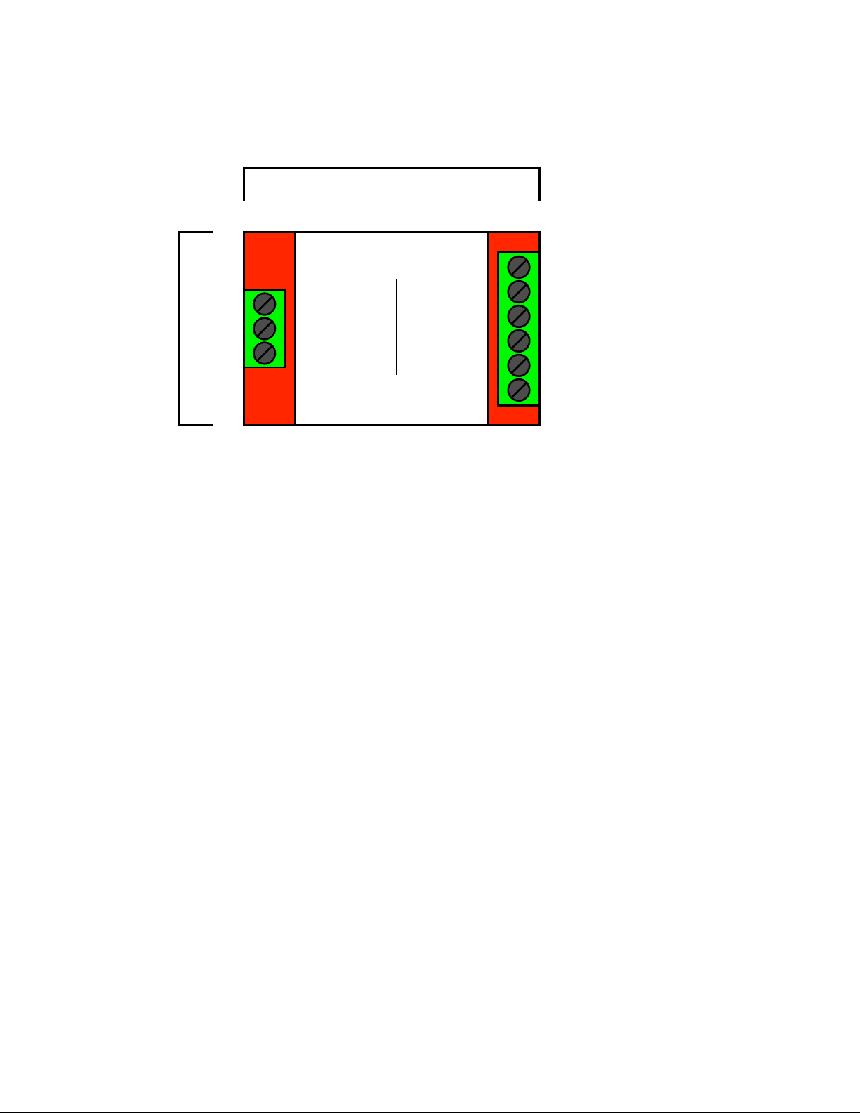
•Wiegand input devices must share a common ground connection with the J1 header.#
•Wiegand output devices must share a common ground connection with the J2 header, unless they are
powered with the same power supply.#
Wiegand input data voltage levels:#
•Measure DC voltage between Data 0 IN and Ground, and again between Data 1 IN and Ground on the J1
header. Normally the voltage levels should be at 5VDC or equivalent high voltage if using Wiegand devices
that operate at higher voltages. #
•If the voltage levels are below 4.4VDC, then disconnect the Wiegand device(s) from the J1 header and
measure the devices while they are not connected to anything. The J1 header Wiegand inputs are open
collector and will be at 0VDC while no devices are connected. #
•If the voltage levels of the Wiegand device(s) are below 4.4VDC while it is not connected to other devices,
they the problem lies with that device and not the CVX-OPTW. This may be able to be recovered using
external pullup resistors. Connect a 1K to 2K through-hole resistor to the low data line and a 5VDC output.
This will pull the voltage up to 5VDC.If the voltage level for a Wiegand data line is below 1VDC, then the
line is clamped to ground and cannot be recovered. #
Wiegand output data voltage levels:
•Measure DC voltage between Data 0 OUT and Ground, and again between Data 1 OUT and Ground on
the J1 header. Normally the voltage levels should be at 5VDC or equivalent high voltage if using Wiegand
devices that operate at higher voltages. #
•If the voltage levels are below 4.4VDC, then disconnect the Wiegand device(s) and measure the voltage of
the Wiegand lines on each device separately (inlcudeding the CVX-OPTW J2 header). #
•If the voltage is between 4.4VDC and 1VDC then reconnect the Wiegand device(s) to the J2 header and
jumper the PR +5V pin. This will pull the voltage back up to 5VDC and allow Wiegand data to be passed. #
•If the voltage is below 1VDC on any of the Wiegand devices, then that line is clamped to ground and
cannot be recovered.
Table of contents
Other Cypress Industrial Electrical manuals
Popular Industrial Electrical manuals by other brands

Murata
Murata GRM1885C1H120GA01 Series Reference sheet

PICOLAS
PICOLAS LDP-AV 16N45-40 user manual

Murata
Murata GRM0335C1H4R2BA01 Series Reference sheet

Dynatech
Dynatech ASG 1 Series Instructions for use and maintenance

GFA
GFA ELEKTROMAT FT 80.2-45,00 installation instructions

Murata
Murata GQM2195C2A1R2BB01 Series Reference sheet

Murata
Murata GRM1555C1H8R4WA01 Series Reference sheet

Murata
Murata GRM1555C1H470FA01 Series Reference sheet

Freund
Freund STUN-E512 Translation of operating manual

Eaton
Eaton RMQ-Titan M22 Series Instruction leaflet

PR electronics
PR electronics 3185 product manual

Murata
Murata GQM2195C2E360JB12 Series Reference sheet