CustomCrimp CC650 User manual

CC650 Production / Industrial Hose Crimper
Updated 10/26/2017
CC650 CRIMPER OPERATORS MANUAL
WITH ACTTM CONTROLLER
The CC650 Series hose crimper with the Patented ACT™ Controller and 350
tons of crimping force has the capability to crimp hoses from ¼" up to 6" in diameter.
UNIQUE USER FRIENDLY PATENTED ACTTM CONTROLLER
• Fully adjustable crimp to diameter.
• Production capabilities.
• Pressure Compensation uses pressure to eliminate “trial and error”.
• Memory capacity for accurate repeatability.
• Automatically converts inch to mm and mm to inch so that no calculation is ever
required.
Th
Th
Th
Th
e
e
e
CC
CC
CC
CC
CC
6
65
65
65
65
0
0
0
0
0
S
S
Se
Se
Se
i
ri
ri
ri
es
es
es
h
h
h
h
os
os
os
e
e
e
cr
cr
cr
i
im
im
im
pe
pe
pe
r
r
r
i
wi
wi
wi
th
th
th
th
t
t
t
t
h
he
he
he
P
P
P
P
t
at
at
at
en
en
en
t
te
te
te
d
d
d
d
C
AC
AC
AC
AC
T™
T™
T™
T
C
C
C
C
C
on
on
on
t
tr
tr
tr
l
ol
ol
ol
l
le
le
le
r
r
r
an
an
an
d
d
d
d
3
35
35
35
35
0
0
0
0
0
Max Head Opening W/O
Dies: Can accommodate 6"
150 lbs SAE flange.
Max Head Opening W/O
286mm
11-¼"
•
Pressure
Compensation
• Memor
y
capaci
ty
f
or ac
c
• Automaticall
y
converts i
required.

CC650 Production / Industrial Hose Crimper
2
SAFETY PRECAUTIONS
• READ INSTRUCTIONS AND IDENTIFYALL COMPONENT PARTS BEFORE USING CRIMPER.
• CRIMPER CC650 CAN PRODUCE 350 TONS OF CRIMPING FORCE.
• KEEP BOTH HANDSAWAY FROM PINCH POINTS.
• CONSULT HOSE AND FITTING MANUFACTURER FOR CORRECT MACHINE SETTINGS
AND CRIMP MEASUREMENTS.
• ALWAYS WEAR EYE PROTECTION.
SAFETY PRECAUTIONS
! !

CC650 Production / Industrial Hose Crimper
3
SAFETY PRECAUTIONS-----------------------------------------------------------------------------------------------------2
COMPONENT PARTS & TECHNICAL DATA--------------------------------------------------------------------------------------------------4
INITIAL SET UP-----------------------------------------------------------------------------------------------------------------------5
ADAPTER DIE INSTALLATION------------------------------------------------------------------------------------------------6
HYDRAULIC DIE INSTALLATION-----------------------------------------------------------------------------------------------7
LUBRICATION PROCEDURE-------------------------------------------------------------------------------8
AccuCrimp ACTTM CONTROL PANEL------------------------------------------------------------------------------------9
AccuCrimp ACTTM CONTROL PANEL QUICK START--------------------------------------------------------------------------------10
AVAILABLE CC650MIC MANUAL DIAL MICROMETER----------------------------------------------------------------------------------18
PLC RESET PROCEDURE---------------------------------------------------------------------------------------------------------19
TROUBLESHOOTING------------------------------------------------------------------------------------------------20
CC650 CRIMPER REPLACEMENT ACCESSORIES-------------------------------------------------------------------------21
COMPONENT PARTS BREAKDOWN--------------------------------------------------------------------------------------------22
CC650 DIE PART IDENTIFICATION--------------------------------------------------------------------------------------------34
CC650 PREVENTATIVE MAINTENANCE PACKAGE------------------------------------------------------------------35
CUSTOMCRIMP® “NO-NONSENSE” WARRANTY STATEMENT---------------------------------------------------------------37
CUSTOMCRIMP® CONTACT INFORMATION--------------------------------------------------------------------------------------38
TABLE OF CONTENT

CC650 Production / Industrial Hose Crimper
4
COMPONENT PARTS & TECHNICAL DATA
Technical Data CC650 / CC650MIC
350 Ton
*6SP: 3"
*Max Industrial: 6"
L: 49" x W: 54" x H: 69"
Weight: 4,000 lbs
CC650 Power: 7.5HP/230V/3Phase (Standard)
7.5HP/440V-480V/3Phase (Optional)
5HP/230V/1Phase (Optional)
CC650 Adjustability: Inch / Metric
CC650MIC Power: 5HP/230V/3Phase (Standard)
5HP/440V-480V/3Phase (Optional)
5HP/230V/1Phase (Optional)
CC650MIC Adjustability: Metric
Die series 99S / 160S / 160OB
Opening w/o dies: 286mm / 11.25"
Master die inside diameter: 160mm / 6.29"
Master die travel: 128mm / 5"
Reservoir capacity: 24 US Gallons
Oil type: ISO 46 Hydraulic Oil
49"
54"
69"
7.5 HP motor high
capacity pump
Hydraulic 99mm Die
Storage Pockets
Foot Pedal for use in Semi
and Full automatic mode
Main Power
Switch
Reservoir
Small Footprint for
minimum use of space
Industrial Die
Storage Shelves
Patented ACTTM Controller
Adjustable Mirror
Manual
Back Stop
Available Manual Dial
Adjustment Micrometer *Crimper capacity is estimated based ontypical 1-piece
fitting. Actual results may vary depending on the hose
and fitting manufacturer.
Max Head Opening W/O
Dies: Can accommodate 6"
150 lbs SAE flange.
Max Head Opening W/O
286mm
11-¼"
Manual Back Stop: Makes hydraulic hose
production crimping fast and accurate.
Easy Maintenance: Through
the 12 lubrication fittings.
Industrial Crimp Calculator: Takes
guesswork out of industrial crimping.
Patented ACT™ Controller:
Offers 4 language settings to choose
from English, Espanol, Deutsch
and Francais.
Features Of Operator Interface:
User Friendly navigation, Manual Mode,
Semi Auto Mode, Full Auto Mode and
Production Features.

CC650 Production / Industrial Hose Crimper
5
INITIAL SET UP
• Check the oil level in the sight glass gauge on the front of the
reservoir.
• 24 U.S. gallons of ISO 46 hydraulic oil is required to completely
refill the reservoir.
Note:Oil canbedrainedfromeitherofthe twoports atthe rearbottom
of the reservoir.
An additional oil cooler, while not normally required, can be plumbed
into the two ports at the rear bottom of the reservoir.
• Check electrical circuit to be certain that it matches to the crimper
requirements as shown on the voltage decal on the electrical
enclosure.
Electrical Requirements:
7.5HP/230V/3Phase (20 Amp)
7.5HP/440V-480V/3Phase (20 Amp)
5HP/230V/1Phase (30 Amp)
• Plug the cord directly into the appropriate wall outlet.
Caution: Do not run the crimper on an extension cord as low voltage
can damage the motor and / or electrical components.
• Check to be certain that the motor rotates in the direction of the
arrow shown on the motor housing.
• Ifmotor rotation isincorrect reverseany two hotwires inthe crimper
plug. (Note: This is applicable to 3 phase circuits only)
Note: Damage to the pump can result if the motor does not rotate in
the correct direction.

CC650 Production / Industrial Hose Crimper
6
ADAPTER DIE INSTALLATION
Photo #3
Photo #4
Photo #1
Photo #2
ADAPTER DIE INSTALLATION:
Note: 160 mm to 99 mm Adapter Dies are furnished with the crimper.
Adapterdies areheld inplace bythe dielockingpins(asshowninphoto#1).
The I.D. of the adapter dies must match the O.D. of the corresponding
adapter die or hydraulic die or accurate crimps can not be made.
Note: Tap the START button then CHANGE DIES button in
the lower left corner of the screen; it will start to flash.
This button allows you to “jog” the crimper head in and out during
die installation using the green CLOSE and OPEN button below
the screen on the front of the ACT™ Controller.
• Bring the master dies to the fully opened position (as shown
in photo #2). To have access to the (8) master die locking studs.
• Install the 160 mm to 99 mm Adapter Dies (as shown in photo #3).
Note: The die size stamped on the face of the adapter dies should face
toward the operator.
Note: Use the T-Handle Wrench provided to loosen and tighten
the master die locking studs to secure the adapter dies
(as shown in photo #4).

CC650 Production / Industrial Hose Crimper
7
HYDRAULIC DIE INSTALLATION:
• With the 160 mm to 99 mmAdapter Dies installed, use the Quick Change
Tool to install the hydraulic dies.
The I.D. of the adapter dies must match the O.D. of the corresponding
hydraulic die or accurate crimps can not be made.
Note: Tap the START button then CHANGE DIES button in the lower
left corner of the screen; it will start to flash. This button allows you to
“jog” the crimper head in and out during die installation using the green
CLOSE and OPEN button below the screen on the front of the ACT™
Controller.
• Bring the crimper head to fully opened position and install the Hydraulic
Dies with the quick change tool (as shown in photo #1).
Note: The die size stamped on the face of the hydraulic dies should face
toward the operator.
• Align the studs of the Hydraulic Dies with the holes in the
Adapter Dies and with the crimper in manual mode SLOWLY
close the crimper head on the hydraulic die set (as shown in
photo #2).
• Bring the crimper head to a fully closed position (as shown
in photo #3).
• Remove the quick change tool as shown in photo #4).
Note: The Hydraulic Dies may also be inserted manually with the crimper
head in the fully open position.
Note: For Hydraulic Die removal, place the crimper in manual mode and
bring the crimper head to a fully closed position. Insert the quick change
tool and open the crimper head releasing the Hydraulic Dies form their
spring retention holes.
Photo #1
Photo #3
Photo #4
Photo #2
HYDRAULIC DIE INSTALLATION

CC650 Production / Industrial Hose Crimper
8
Note: Use the mini grease gun w/ flush fitting adapter and CrimpX grease
(supplied with crimper) or a high quality moly-disulfide grease.
Failure to lubricate the crimper can cause premature failure,
loss of accuracy and may result in costly repairs to the crimper.
• Lubricate the crimping head after each 100 crimping cycles
or at the start of each shift if the crimper is used in a production
setting.
Note: Tap the START button then CHANGE DIES button in the lower
left corner of the screen; it will start to flash. This button allows you to
“jog” the crimper head in and out during die installation using the green
CLOSE and OPEN button below the screen on the front of the ACT™
Controller.
• Bring the master dies to the fully closed position, and lubricate the
master dies through the 8 lubrication fittings in the protective plates (as
shown in photo #1).
• With the dies still in the fully closed position, lubricate the (2) lubrication
fittings visible through the two top lubrication fittings in the face of the
crimper (as shown in the photo #2).
• Bring the master dies to the fully open position, lubricate the crimper
through the lubrication fittings visible through the two bottom lubrication
fittings in the face of the crimper (as shown in the photo #3).
Note: Parking the crimper in the full open position when not in use will
prolong the life of the master die springs.
• Check the wear surfaces for grease. If the surfaces show any signs
of wear, apply more grease. If you touch the wear surfaces, you should
see a thin layer of grease on your finger.
LUBRICATION PROCEDURE
Photo #1
Note: This specific style of grease gun
flush fitting adapter must be used to
lubricate the CC650 crimper.
Photo #2
Photo #3

CC650 Production / Industrial Hose Crimper
9
EMERGENCY STOP
MANUAL MODE FUNCTION: CLOSE DIES
AUTO MODE FUNCTION: CYCLE START
MANUAL MODE FUNCTION: OPEN DIES
AUTO MODE FUNCTION: CYCLE STOP
NOTE:
IF THE CRIMPER IS IN MANUAL MODE,THE GREEN OPEN/CLOSE BUTTONS WILL OPEN AND CLOSE THE
CRIMPER HEAD.
IF THE CRIMPER IS IN AUTO MODE, THE BUTTONS FUNCTION AS CYCLE START AND CYCLE STOP BUTTONS.
IF THE CRIMPER IS IN SEMI-AUTO MODE, PRESSING THE FOOT SWITCH OR THE CLOSE BUTTON WILL
CLOSE THE CRIMPER HEAD AND RELEASING WILL HALT THE CLOSING ACTION.
AccuCrimp ACTTM CONTROL PANEL
Products covered by all or some of these Patents:
US 7,383,709; US 8,230,714; EP 1,909,987 and Patents Pending.
6" TOUCH SCREEN
STYLUS PEN
USB PORT

CC650 Production / Industrial Hose Crimper
10
AccuCrimp ACTTM CONTROL PANEL QUICK START
While the ACTTM crimper has the ability to perform a number of
fully automatic functions, manual operation is also possible.
To make a manual crimp, two numbers are needed:
The closed diameter of the die (in either inches or mm).
The finished crimp diameter (in either in or mm)
That’s all you need to know. ACTTM does the rest.
TO MAKE A MANUAL CRIMP:
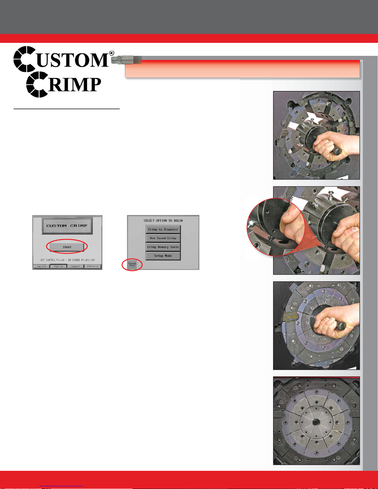
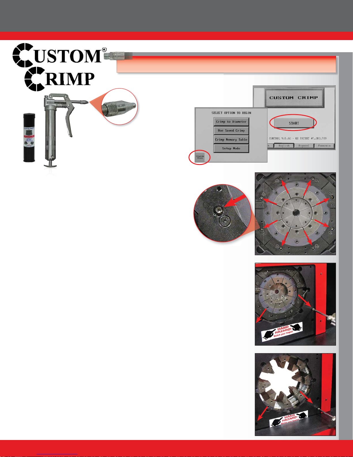
• Press START Button.
• Select CRIMP TO DIAMETER.
• Enter the closed diameter of the die set in either in or mm
and press ENTER. Note: for a 25mm die, enter 2500.
ACTTM will add the decimal point.
Decimal point entry:
For 1.56 inch entry, enter 1560 (Controller supplies 3
places for entries in inches).
For a 50.0 mm entry, enter 5000 (Controller will supply 2
decimal places for entries in mm).
• Enter the finished crimp diameter and press ENTER.
• From the ENTER CRIMP screen, press the MANUAL button
to put the crimper in manual mode.
• Confirm that the die and finished crimp diameters are correct
and that MANUAL MODE is displayed.
• Press and hold the green CLOSE button until the crimper
stops closing.
• Check the final crimp diameter. If a minor correction is
required see HOW TO MAKE MINOR CORRECTIONS.
Tip: Pressing the CHANGE DIES button allows the crimper
head to be fully opened or closed with the green OPEN-CLOSE
buttons on the controller front panel When the CHANGE DIES
button is blinking the dies can be opened and closed manually
without altering any of the crimper settings.
Note: When using the overbore (OB) dies you must
use the SAVED DIE feature. Press the USE SAVED
DIE to select the correct die set from the die memory
table.

CC650 Production / Industrial Hose Crimper
11
HOW TO MAKE MINOR CORRECTIONS
• Due to variations in hose and fitting tolerances a minor crimp
adjustment may be required if the measured diameter of the final
crimpisnotwithinthehoseandfittingmanufacturer’sspecifications.
ACTTM technologymakesminor corrections a simpleprocess which
requires no addition or subtraction.
Ifthe finishedcrimpdiameteris not within therequiredspecifications:
• Press the ADJUST CRIMP button.
• Enter the measured diameter of the fitting in either inches
or mm (Do not enter the amount of correction)and press
ENTER.
• Press OK.
• Make another crimp and verify that the fitting is within
specifications.
EXAMPLE: If the hose and fitting manufacturer specifies that the
finished crimp should measure 1.500 to 1.520 and the measured
crimp diameter was 1.530, simply enter the measured diameter
(1530 - Controller will supply 3 decimal places) and press SAVE.
The finished crimp diameter can be entered in either in or mm and
ACTTM will make the conversion.
While a single correction will usually bring the hose and fitting into
specifications, the process can be repeated as many times as is
required.
AccuCrimp ACTTM CONTROL PANEL QUICK START

CC650 Production / Industrial Hose Crimper
12
HOW TO ADD A SAVED DIE
Up to 50 different dies can be saved in the computer memory.
These dies can be recalled in the set up process eliminating the
need to re-enter the die size each time.
To enter a saved die:
• From the OPTION screen, press SETUP MODE.
• Select SAVED DIES.
• Select the save position (1-50) where the die is to be saved
and press the EDIT button.
• Enter a die description (up to 12 alpha/numeric characters).
• Enter diameter units (inch or metric).
• Enter the closed diameter of the die.
• Press SAVE and EXIT.
• The saved die will now appear on the SELECTED DIE
screen. From this screen individual dies can be cleared or
edited.
HOW TO RECALL A SAVED DIE
• SelectCRIMP TO DIAMETER,and from the OPTION screen,
select USE SAVED DIE.
• Select the saved die (1-50) and press LOAD and then OK.
The die parameters will now be used for the crimp process.
From the ENTER CRIMP screen press MANUAL.
• The saved die will now be shown on the crimp parameters
screen.
AccuCrimp ACTTM CONTROL PANEL QUICK START

CC650 Production / Industrial Hose Crimper
13
HOW TO ADD A SAVED CRIMP
• Adjust the die diameter and crimp diameter as required and
place the crimper in MANUAL mode.
• Press SAVE.
• Select a location (1-100) and press EDIT.
• Enter a description (up to 12 characters).
• Press SAVE and EXIT.
• The die and crimp setting can now be recalled from the
saved location as required.
TO RECALL SAVED CRIMP
• Select USE SAVED CRIMP from the option screen.
• Select a previously saved crimp from location 1-100.
• Press LOAD.
• Press OK.
• The saved crimp will appear on the manual screen.
AccuCrimp ACTTM CONTROL PANEL QUICK START

CC650 Production / Industrial Hose Crimper
14
AccuCrimp ACTTM CONTROL PANEL QUICK START
FULL AUTO MODE
With the crimper in FULL AUTO mode additional functions are available:
• The crimper will cycle automatically from the CRIMP button
on the touch screen, the green CYCLE START button on the
panel, or the foot switch.
•To set the position to which the dies will retract, close the
crimper to the desired retract position prior to pressing the
FULL AUTO button.
Note: The retraction position must be set a minimum amount above the
finished crimp diameter or the crimper will not retract. The minimum
retraction diameters are:
CC38 - Crimp Diameter plus 2 mm
CC4-50 - Crimp Diameter plus 2 mm
CC60 - Crimp Diameter plus 3 mm
• Pressing the FULL AUTO button will toggle the crimper into
SEMI-AUTO mode. In SEMI-AUTO mode, pressing the FOOT SWITCH
orthe CLOSE button will closethe crimperhead andreleasing itwill cause
the head to stop closing. This mode allows the crimper to be jogged into
position allowing more precise positioning of a fitting in the dies.
Pressing the SEMI AUTO button will toggle the crimper back to FULL
AUTO mode
InFULLAUTO mode pressing the footswitch will start thecrimpcycle and
the dies will stop closing when the crimp cycle is complete.
• The COUNT function is activated allowing the operator to
monitor the number of crimps made.
• A measurement can be required after a preset number of
crimps. See SET REQUIRED MEASUREMENT
SET REQUIRED MEASUREMENT
• Press the PRODUCTION button.
• Determine if 1 or 2 crimps will count as a crimp
• Toggle the CRIMP ADJUSTMENT REMINDER to ON.
• Set the COUNTS BETWEEN CRIMP MEASUREMENTS
to the desired number and press OK.
• At the set interval, the ADJUST CRIMP screen will come up
and the operator will be asked to measure the last crimp and
enter a correction if required.

CC650 Production / Industrial Hose Crimper
15
AccuCrimp ACTTM CONTROL PANEL QUICK START
ADJUST CRIMP COUNT
If a production operation is interrupted for some reason, it is
possible to reset the counter to where the operation was at the
point of interruption.
• Press the Adjust Count button from the auto crimp screen.
• Press the Crimp Counter and reset the count to the desired
point.
ACTTM ADDITIONAL FEATURES
• Additional features and functions of the ACTTM controller can
beaccessed by pressing theMORE button onthe MACHINE
SET UP screen.
• When “Allow Crimp to Diameter” is set to “YES”, all of the
adjustment functions of the crimper are available. When
“Allow Crimp to Diameter” is set to “NO” only the settings
entered as a saved crimp can be used.
• English or Spanish language options are available.
• The “Use Pressure Compensation” is set to “YES” for all
crimpers equipped with a pressure transducer. A security
code is required to turn this function on or off.

CC650 Production / Industrial Hose Crimper
16
AccuCrimp ACTTM CONTROL PANEL QUICK START
ACTTM ADDITIONAL FEATURES
Pre-Loaded Crimp Specifications
In addition to the ability to store up to 50 user entered dies and
150 user entered crimp settings, the ACT™ Controller has the
capability of accepting pre loaded manufacturer’s crimp specifi-
cations.
CustomCrimp® does not maintain these specifications as they
are proprietary to the individual hose and fitting manufacturer.
If, however, your ACT™ Controller was pre loaded with a manu-
facturer’s crimp specifications or if they are available to you, they
are accessed in the following manner:
• Press the Crimp Memory Table Button.
• Press the access button to bring up the stored crimp specifi
cations.
• Scroll through the crimp specifications to select the correct
one. The right hand rocker button moves through the crimp
specs one line at a time and the left hand rocker button moves
one screen at a time.
• When the correct crimp specification is selected, press the
highlighted selection and then the Load button and select OK
to write the data to the ACTTM Controller.
• This will bring up the familiar crimp screen and the crimper
can then be operated in the normal manner.

CC650 Production / Industrial Hose Crimper
17
INDUSTRIAL CRIMP CALCULATOR
The Industrial Hose Crimp Calculator is part of the ACTTM controller
package on many Custom Crimp®crimpers capable of crimping industrial
hoses. With a few simple measurements, it takes the guess work out of
industrial hose crimping and eliminates the need for charts and graphs.
Note: Not all ACTTM controllers have the Industrial Crimp Calculator
software. Contact your sales specialist for information on a specific
crimper.
• Press the CRIMP TO DIAMETER button.
• Press the INDUSTRIAL CRIMP Button.
• Press MEASURE.
If the hose diameter is known or a pi tape is being used, enter
the hose O.D.
If hose O.D. is not known, press MEASURE for wall
thickness options.
• Measure the wall thickness of the hose. Press the right arrow and
take 2 more measurements of the hose wall thickness.
• TheIndustrial CrimpCalculatorwillaverage thethreemeasurements.
• Enter the stem diameter of the fitting. For example: If the stem
diameter is 4 inches, you would enter 4000 and the ACTTM controller
would supply the decimal place.
• Measure and enter the wall thickness of the ferrule.
• Next enter a compression factor. While this can vary depending
upon the specific hose and manufacturer, the following guidelines
are a starting point:
Standard Industrial hose (approximately 1/4 inch
wall thickness): 22%
Standard lay flat hose: 11%
Note: Contact your hose and fitting manufacturer for the
compression factor to use on a specific hose and ferrule,
• Press PROCESS and enter the die diameter if you have not already
done so.
• Select and install the correct die set for the combination of hose and
fitting being crimped.
• Press MANUAL and proceed to crimp the hose.

CC650 Production / Industrial Hose Crimper
18
CC650 MIC MANUAL DIAL MICROMETER
The CC650 MIC is available with a manual dial micrometer in place of
theACTTM controller. Set up and adapter and die installation are identical
to the CC650 ACT model.
The micrometer is a direct reading metric micrometer.
With the micrometer set at zero, the die set will close to the fully closed
diameter stamped on the face of the die.
Thenumber set on themicrometer willbe theamount ABOVE theclosed
diameter of the die at which the dies will stop closing.
Example:
If the required final crimp diameter for the hose and fitting being
crimped is 65.5 mm, the correct die set to use would be a 63 mm
die set. The micrometer would be set at 2.5 mm as shown, and the
final crimp diameter would be 65.5 mm (63 mm-closed die diameter
plus 2.5 mm)
Opening and closing of the crimper head is controlled with the foot
switch. Press and hold the foot switch until the crimp is complete and
the dies stop closing.
Always check the hose and fitting with a caliper to be certain that the final
crimp diameter is in accordance with the hose and fitting manufacturers
specifications.

CC650 Production / Industrial Hose Crimper
19
PLC RESET PROCEDURE
PLC RESET PROCEDURE:
ThePLC(ProgrammableLogic Controller) requires a relativelyconstant source of electricalpower. Powersurges, outagesor
drops in power can cause the PLC to lose its settings. This may result in missing or misplaced information on the controller
screen.
RESETTING THE PLC TO ITS ORIGINAL SETTINGS IS A SIMPLE PROCEDURE:
• Open the front of the Control Panel.
• Power up the crimper from the main power switch. The crimper must be powered on during the PLC reset procedure.
• Move the three position toggle switch on top of the PLC right to the STOP position and then left to the RUN position.
• Return the toggle switch to the center TERM position.
• Repeat for the other PLC Unit.
• Cycle the main power off and back on.
• The PLC and the crimper should now operate normally.
• Close the control panel.

CC650 Production / Industrial Hose Crimper
20
TROUBLESHOOTING
PROBLEM: CRIMPER WILL NOT RUN AT ALL
• Check the E-Stop switch to be certain that it is not depressed. A slight twist is required to release switch after it has been
depressed.
• PLC (Programmable Logic Control) must be reset. See instructions on the previous page.
PROBLEM: CRIMPER RUNS BUT IS SLOW OR NON-FUNCTIONAL
• Check supply voltage to see that it matches the voltage specified on the tag attached to the crimper.
Many performance problems are the result of low voltage or inadequate electrical service.
• Check motor rotation and be certain that the motor rotates in the direction of the arrow on the motor housing. For three
phase units rotation can be reversed by switching any two wires in the plug.
PROBLEM: CRIMPER WILL CLOSE ON FITTING BUT DOES NOT DEVELOP POWER TO
COMPLETE THE CRIMP
• Check oil level. Position dies to the fully open position and check oil sight gage in rear of machine. Be sure the oil level is
in the middle of the sight glass. Use ISO 32 or 46 weight hydraulic oil.
PROBLEM: CRIMPER WILL NOT OPEN TO RETRACT POSITION IN AUTO MODE
• Retract position must be at least 3 mm larger than the final crimp diameter.
If problem (s) persist contact Customer Service for additional troubleshooting assistance.
This manual suits for next models
1
Table of contents